controller installation and service personnel must be trained and familiar with the general safety
requirement when working on electrical equipment. Installation and service personnel should also
be familiar with the local laws and regulations and safety requirements.
2Safety instructions
2.1 Symbols explanation
In order to ensure the personal and property safety of the user during installation, or
optimally efficient use of this product, symbols are used highlight the information.
The following symbols may be used in this manual, please read carefully, in order to
make better use of this manual.
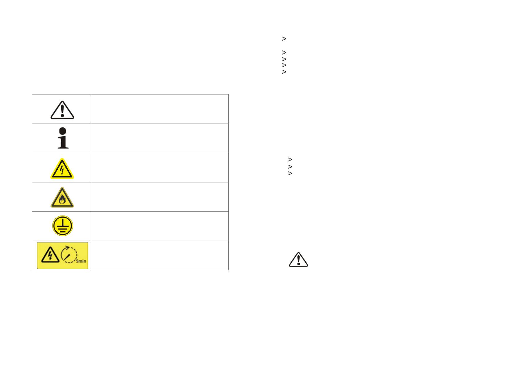
DANGER
DANGER indicates a hazard with a high level of risk which, if not
avoided, will result in death or serious injury.
CAUTION
CAUTION indicates there is potential risk, if not avoided, could
result in equipment malfunction and property damage.
Caution,risk of electric shock
When battery bank connecting point are exposed, there will be
DC voltage in the equipment DC side; and when output breaker is
on, there is a potential risk of electric shock.
Caution, risk of fire hazard
Suitable for mounting on concrete or other non-combustible
surface only.
Protective conductor terminal
The controller has to be firmly grounded to ensure the safety of
personnel.
Risk of electric shock, Energy storage timed discharge Electrical
shock danger exists in the capacitor; the cover shall be
moved at least 5 minutes later after all powers are disconnected.
2.2 Safety instructions
Read this manual carefully before operation. The equipment will not be under warranty if failing
to operate according to this manual.
Operation on the controller must be for qualified electrical technician only.
When controller operating, don't touch any electrical parts except for the touch-screen.
All electrical operation must comply with local electrical operation standards.
Permission from the local utility company is required before installing the PBD and only
professional personnel are qualified for the operation
2.3 Installation
Proper installation requires following all the instructions in the user manual involving
transportation, mounting, wiring and commissioning. ATESS does not cover
warranty for the controller damage due to failing to use it properly.
The protection level of the controller is IP20, which is designed for indoor installation.
Please refer to chapter 5 for installation instruction.
Other notice for using the controller:
Pay attention to the safety instructions listed here and below;
Pay attention to the user manual of energy storage controller;
Technical data related to equipment shall be considered.
2.4 Operator
controller installation and service personnel must be trained and familiar with the general safety
requirement when working on electrical equipment. Installation and service personnel should also
be familiar with the local laws and regulations and safety requirements.
2.5 Important note
Item 1:Static electricity can cause damage to the controller
electrostatic discharge may cause unrecoverable damage to controller internal
components!
When operating the controller, operator must comply with anti-static protection
norms!
Item 2: Restriction
The controller cannot be directly used to connect the life support equipment
and medical equipment!
Item 3: Precautions
Make sure installation tools or other unnecessary items are not left inside the
controller before starting up.
Item 4: Maintenance notice
Maintenance can only be carried out after the controller totally discharged.
controller installation and service personnel must be trained and familiar with the general safety
requirement when working on electrical equipment. Installation and service personnel should also
be familiar with the local laws and regulations and safety requirements.
2Safety instructions
2.1 Symbols explanation
In order to ensure the personal and property safety of the user during installation, or
optimally efficient use of this product, symbols are used highlight the information.
The following symbols may be used in this manual, please read carefully, in order to
make better use of this manual.
DANGER
DANGER indicates a hazard with a high level of risk which, if not
avoided, will result in death or serious injury.
CAUTION
CAUTION indicates there is potential risk, if not avoided, could
result in equipment malfunction and property damage.
Caution,risk of electric shock
When battery bank connecting point are exposed, there will be
DC voltage in the equipment DC side; and when output breaker is
on, there is a potential risk of electric shock.
Caution, risk of fire hazard
Suitable for mounting on concrete or other non-combustible
surface only.
Protective conductor terminal
The controller has to be firmly grounded to ensure the safety of
personnel.
Risk of electric shock, Energy storage timed discharge Electrical
shock danger exists in the capacitor; the cover shall be
moved at least 5 minutes later after all powers are disconnected.
2.2 Safety instructions
Read this manual carefully before operation. The equipment will not be under warranty if failing
to operate according to this manual.
Operation on the controller must be for qualified electrical technician only.
When controller operating, don't touch any electrical parts except for the touch-screen.
All electrical operation must comply with local electrical operation standards.
Permission from the local utility company is required before installing the PBD and only
professional personnel are qualified for the operation
2.3 Installation
Proper installation requires following all the instructions in the user manual involving
transportation, mounting, wiring and commissioning. ATESS does not cover
warranty for the controller damage due to failing to use it properly.
The protection level of the controller is IP20, which is designed for indoor installation.
Please refer to chapter 5 for installation instruction.
Other notice for using the controller:
Pay attention to the safety instructions listed here and below;
Pay attention to the user manual of energy storage controller;
Technical data related to equipment shall be considered.
2.4 Operator
controller installation and service personnel must be trained and familiar with the general safety
requirement when working on electrical equipment. Installation and service personnel should also
be familiar with the local laws and regulations and safety requirements.
2.5 Important note
Item 1:Static electricity can cause damage to the controller
electrostatic discharge may cause unrecoverable damage to controller internal
components!
When operating the controller, operator must comply with anti-static protection
norms!
Item 2: Restriction
The controller cannot be directly used to connect the life support equipment
and medical equipment!
Item 3: Precautions
Make sure installation tools or other unnecessary items are not left inside the
controller before starting up.
Item 4: Maintenance notice
Maintenance can only be carried out after the controller totally discharged.
34


