Page is loading ...

Texmate, Inc.Tel. (760) 598-9899 • www.texmate.com BN-35CL Data Sheet (BN03) Page 1
INTERNATIONAL
CASES
DIN
1/8
1/32
1/32
The BN-Series have a matching DIN case style
that is complementary to the Lynx, Leopard
and Tiger family of meters. BN-Meters are the
OEM’s choice for economical switchboard and
process indication.For economy, each model is
dedicated to a specific application and
designed for quick and easy installation.
General Features Compatibility
Specifications
Typical Application Connections
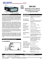
BN-Series, For Those Applications Where Space Is A Premium
BN-Series
Isolated-Power Process Meter in Compact DIN 96x24mm Case.
• INTERNALLY ISOLATED 24VDC power (standard)
• Optional internally isolated 9V, 12V, or 15VDC
power supply
• International standard DIN 96x24mm case
• Short depth case: 2.83" (72mm) behind panel
• 0.56" high red LEDs standard
• Adjustable display brightness
• Optional green or extra bright red LEDs available
• Display Hold and Test
• Auto zero and polarity
• Ideal for OEM applications
The BN-35CL is a streamlined 4 to 20mA current loop
meter. It is specifically designed to be easily user-scaled and
calibrated to almost any conceivable engineering unit, such as
temperature, pressure, viscosity, or flow rates, etc. without
requiring component changes. On site scaling and recalibration
is facilitated by multiturn potentiometers that provide continuous
adjustment within each of three header-programmable full scale
ranges for span and zero offset.
The display is shipped standard with red LEDs, but green
LEDs or super bright LEDs for high ambient light environments
are also offered. Display Segment Test and Hold Reading are
standard features.
BN-35CL
Current Loop Meter
3 1/2 Digit 0.56” LED
in a 1/16 DIN Case
Input Configuration:........Series connection to 4-20mA process loop.
Full Scale Ranges: ..........User adjustable to any scaling between
-1999 to +1999.
Input Impedance:.............70Ω. Maximum 1.4V drop
A/D Converter: .................12 bit dual slope
Accuracy: .........................±(0.05% of reading + 2 counts)
Temperature Coefficient:100 ppm/°C (Typical)
Warm Up Time:.................2 minutes to specified accuracy
Conversion Rate:.............3 conversions per second (Typical)
Display:.............................0.56" High Efficiency red LEDs, Display
Hold and Test provided. Optional green and
super bright red LEDs.
Polarity: ............................Assumed positive, displays negative sign
Decimals:..........................User programmable to 3 positions
Overload Indication:........When input exceeds full scale on any range
being used, most significant "1" digit and
polarity symbol are displayed with all other
digits blank.
Power Supply:..................24VDC @ 90mA (standard) 9VDC @ 200
mA; 12VDC @ 160mA;15VDC @ 120mA;
depending on option selected
Operating Temperature:..0°C to 60°C
Storage Temperature:......-40°C to 85°C
Relative Humidity:...........95% (non condensing)
Case Dimensions: ...........Bezel: 96X24 mm (3.62”X 0.95”)
Depth behind bezel: 56.5 mm (2.23”)
Plus 27 mm (1.06”) for Push-On connector
or plus 17.5 mm (0.68”) for Edge connector
Weight:..............................85 gms. (3 oz)
125 gms. (4.4 oz) when packed
INPUT
HIGH
INPUT
LOW
BN-35CL
Other devices can also
be added to the loop.
24V External
Loop Supply
+_
+
_
9
L
10
K
10 to 1500
1400 to 3000
2900 to 4000
Negative
Mid Range
Positive
CAL
Zero Offset
Range Header Span
Range
Header
Zero
Span
BN-35 . . . . . . . . . . .0.2/2/20/200V DC ranges, 3.5 digit, 5V DC Powered
BN-35BCD . . . . . . .Parallel or Multiplex BCD, 3.5 digit, 5V DC Powered
BN-35CL . . . . . . . .4 to 20mA, Isolated 24V DC, 3.5 digit
BN-35I . . . . . . . . . .0.2/2/20/200V DC ranges, Isolated 24V DC, 3.5 digit
BN-40BCD . . . . . . .Parallel or Multiplex BCD, 4.0 digit, 5V DC Powered
BN-45 . . . . . . . . . . .2/20/200V DC ranges, 4.5 digit, 5V DC Powered
BN-45I . . . . . . . . . .2/20/200V DC ranges, Isolated 24V DC, 4.5 digit

Texmate, Inc.Tel. (760) 598-9899 • www.texmate.comPage 2 BN-35CL Data Sheet (BN03)
Functional Diagram
Connector Pinouts
Component Layout
BN-35CL Functional Diagram
GND
1M
Span Range
Header
0.22µF
Span
Pot
25.5
10 to 1500
1400 to 3000
2900 to 4000 1M
45.3
45.3 Zero
Pot
–5V
+5V
+1.25V
31K6
1M
78K7
50K
63K4
16K2
–1.25V
Negative
Zero Offset
Range Header
Mid Range
Positive
CAL
+24V Power
Power GND
DP Common
Display Test
Hold
Blank/Dim
1XX•X DP
1X•XX DP
1•XXX DP
Input LO
Input HI
0.56" Display
GND
+5V –5V
GND
GND
4K7
470
470
470
J7 J6
J4
J5
470K
56K
100K
+5V
48KHz
Clock
Circuit
EMI Filter
Isolated
Switching
Supply -5 V DC
+5 V DC
To Display
1,A
8,J
H
9,K
10,L
15,S
2,B
3,4,C,D
13,P
12,N
14,R
12 Bit
Dual Slope
A to D
Converter
& Display
Driver
Input HI
Integrator
Input LO
Hold
Test
Blank and
Dim Circuit
The Texmate model BN-35CL interconnects by means of a stan-
dard PC board edge connector having two rows of 15 pins,
spaced on 0.156" centers.Texmate also offers a Push-On screw
terminal connector that provides a great advantage in ease-of-
use (see pg. 3). Connectors are available from Texmate.
Pins 1 & A - Positive DC Power Input: These pins are
internally connected together.The positive end of the DC
power is connected to these pins.The standard BN-35CL
meter is designed to be powered from a 24VDC power
supply. Optional 9V, 12V, or 15VDC powered models are
also available. Before using the meter, make sure that
the appropriate power is being applied. The BN-35CL
meter generates a ±5V supply internally that is isolated
from the applied DC power.
Pins 2 & B - Hold Reading: These pins are internally
connected together. If these pins are left unconnected,
the meter will operate in a free-running mode. When this
pin is connected to the Common Pin S, the meter will
latch up. A/D conversions will continue, but the display
will not be updated until Pins 2 & B are disconnected
from Pin S.
Pins 3, 4, C, and D - Negative DC Power Input: These
SPAN ADJUST Header
This three position header enables the SPAN Pot, in three equal over-
lapping 37% steps, to precisely scale down the input Signal Span, to pro-
vide any required Digital Display Span. Without any scaling or offset, a
4mA to 20mA input would produce a digital output of 1000 to 5000, which
is a Digital Display Span of 4000 counts.
SPAN
Turn Clockwise to
Increase Reading
To the
Right Rear
SPAN Potentiometer (Pot)
The 15 turn SPAN Pot is always between the distiller
and the zero pot (as viewed from the front of the meter).
Typical adjustment is 37% of the input signal range.
37%
SPAN Pot % 37% 37%
37%
Signal Span % 75% 100%
SPAN Adjust
Header position 10 to 1500 1400 to 3000 2900 to 4000
10 - 1500
1400 - 3000
2900 - 4000
Span Range
Acts like a 45 Turn Potentiometer
Input LO
Equivalent
Circuit
Input HI
Signal Conditioning Components
Span Pot
Zero Pot
Span Adjust
Header
Zero Offset
Header
pins are internally connected together.The negative end
of the DC power is connected to these pins. The stan-
dard BN-35CL is designed to be powered from a 24VDC
supply. Optional 9V, 12V, or 15VDC powered models are
also available. Before using the meter, make sure that
the appropriate power is being applied. The BN-35CL
meter generates a ±5V supply internally that is isolated
from the applied DC power.
Pins 8 and J - Display Test: These pins are internally
connected together. All numeric display segments will
light up when this pin is connected to the Common Pin
S.
Pins 9 and K - Signal High Input: These pins are inter-
nally connected together. Signal high input for the meter.
Pins 10 and L - Signal Low Input: These pins are inter-
nally connected together. Signal low input of the meter .
Pins 12 & N, 13 & P and 14 & R - Decimal Points:
These are the decimal point pins. Connecting any of
these pins to the Decimal Select Common Pin 15 makes
that particular decimal point come on.
Pin 15 - Decimal Select Common: This pin is the inter-
nal supply ground which is isolated from Pins C, D, 3,
and 4. .The decimal point pins must be connected to this
pin to come on.
Pin S - Hold/Test Common: This pin is connected to the
internal supply ground which is isolated from Pins C, D,
3 and 4. The Hold and Test pins must be connected to
this pin to be activated.
A
123456789101112131415
BCDEFH KJLMNPRS
PCB
Rear View of Meter
METER REAR WITH PCB EDGE CONNECTOR MOUNTED
(For mounting of screw terminal blocks see rear page)
Positive DC Power Input - 1
Hold Reading - 2
Negative DC Power Input - 3
Signal Low Input - 10
A - Positive DC Power Input
B - Hold Reading
L - Signal Low Input
J - Display Test
K - Signal High Input
5
Negative DC Power Input - 4
6
7
Display Test - 8
Signal High Input - 9
D - Negative DC Power Input
E
F
H
FINE "SCRAPE OFF" TRACKS SOLDER JUNCTION
COMPONENT SIDE PINS SOLDER SIDE PINS
Decimal Points - 12
Decimal Points - 13
Decimal Points - 14
11 M
N - Decimal Points
P - Decimal Points
R - Decimal Points
C - Negative DC Power Input
Decimal Select Common - 15 S - Hold/Test Common

Texmate, Inc.Tel. (760) 598-9899 • www.texmate.com BN-35CL Data Sheet (BN03) Page 3
Texmate Produces Thousands of
Custom OEM Face Plates
Have Texmate Design and Install a
Custom Face Plate to Suit your
Next project!
• Custom face plates have a non-
recurring artwork charge. A serial
number is then assigned to each
artwork, to facilitate re-ordering.
• Small Run or One-Off custom face plates incur an installation
charge, and are generally printed on a special plastic film,
which is then laminated to custom faceplate blanks as required.
• Large Run (250 pieces min): custom face plates are produc-
tion silk screened, issued a part number, and held in stock for
free installation as required by customer orders.
• OEMs may also order Custom Meter Labels, Box Labels
Custom Data Sheets and Instruction Manuals.
Opening Back Panel
Power Supply
Custom Face Plates
The BN-35CL ships from the factory with an isolated 24VDC
power supply.
Unscrew the knurled collars, and remove the mounting clips.
Snap out the rear plastic plate. The BN-35CL printed circuit
board can then be easily removed by sliding it out from the rear
of the case .
Push-On Screw Terminals
Texmate’s exclusive optional Push-On Connectors combine an edge
card connector and a 10 position screw terminal block. Push-On
Connectors are ordered preconfigured for each specific power supply
voltage and each optional power supply available for the BN-Series.
They provide the greatest convenience and ease of use
Pinouts are marked
on Connector
Connector can be
securely attached
to case with screws
Zero Offset Range Header CALIBRATE position,
Zero Pot Disengaged
Negative Offset
Decreases Digital Reading Positive Offset
Increases Digital Reading
Mid Range
Offset Range -3000 to -300
2700 Counts 2000 Counts 2300 Counts
ZERO Pot Span
-300 to +2000-1000 to +1000
Calibrate
Positive
Mid Range
Negative
Zero Range
ZERO
Turn Clockwise to
Increase Reading
To the
Left Rear
ZERO Potentiometer (Pot)
The ZERO Pot is to the right of the SPAN Pot. It
enables the Digital Display Span to be offset 2000
to 2700 counts, depending on the Zero Offset
Range Header position selected.
ZERO OFFSET RANGE Header
This four position header enables the ZERO Pot to offset the Digital
Display Span -3000 to +2000 counts with a user selectable Negative
offset, Mid-range (- & + offset), Positive offset, and a Calibrate position
(ZERO Pot disengaged).The Calibrate position facilitates a simple two
step calibration with no interaction between Span and Offset.
Calibration Procedure
The first step is to disengage the ZERO Pot and scale down the Signal
Span input to produce the desired Digital Display Span output.
Signal Span is defined as the total change of signal input that would
be required for a specific change of the Digital Display. The largest
Signal Span that can be specified with a 4 to 20mA input is 16mA. A
4mA Signal Span proportionately scaled can meet full scale display
accuracy.
Digital Display Span is defined as the exact total in counts, that the
display would change within a specific Signal Span. The largest
Digital Display Span that can be displayed is -1999 to +1999 (4000
counts).16mA can not display +4000, so instead 4mA can be scaled
to +1000.
The second step is to select a Zero Offset Range and offset the Digital
Display Span with the ZERO Pot, until the desired reading is displayed.
Maximum offset is -3000 to +2000 counts. A Digital Display Span of
4000 counts requires an offset of -3000 to display -1999 to +1999.
For example: A 4 to 20mA input to read -40.0 to +199.9
Signal Span = 16mA, Digital Display Span = 2400 counts.
1. Remove the meter from its case and set the Zero Offset Range
Header to the Calibrate position. Select the 1400 – 3000 position on
the Span Adjust Header and slide the meter back into the case.
2. Connect power to the meter and apply 4mA (25% of 16mA). Adjust
the SPAN Pot until the display reads +600 (25% of 2400).The meter
is now scaled for a Signal Span of 16mA and a Digital Display Span
of 2400 counts. In the example 4mA should read -400 and 20mA
read 1999, therefore the Digital Display Span should be offset by -
1000.
3. Disconnect power and remove the meter from the case, select the
Negative offset position on the ZERO OFFSET RANGE Header, and
slide the meter back into the case.
4. Connect power to the meter, apply 4mA and adjust the ZERO Pot
until the display reads -400.With the Digital Display Span now offset
by -1000 counts, the meter will read -400 for a 4mA input, and read
+1999 for a 20mA input.Select decimal point 1XX•X to display -40.0
to +199.9.
SPAN RANGE
10 - 1500
1400 - 3000
2900 - 4000
CALIBRATE
NEGATIVE
MID RANGE
POSITIVE
ZERO RANGE
CURRENT SOURCE
OR
2 - WIRE
SIMULATOR
BN-35CL
+9, K
10, L
INPUT HIGH
INPUT LOW
_
CN-PUSH/BN
PCB Edge Connector
A standard 30-pin edge connector (two rows of 15 pins on
0.156" centers) may be used to connect the BN-35CL meter.
Order part no. CN-L15.
Optional PCB Edge Connector

Texmate, Inc.Tel. (760) 598-9899 • www.texmate.comPage 4 BN-35CL Data Sheet (BN03)
BN Case Dimensions and Panel Cutouts
Ordering Information
96 mm
(3.78")
1/16 DIN (96x24mm)
24 mm
(0.95")
3 mm
(0.12")
typical
FRONT VIEW
PANEL CUTOUT
22.2 mm
(0.88")
92 mm
(3.62")
21.85 mm
(0.86")
91 mm
(3.59")
Case will mount in
standard 1/16 DIN cutouts
TOP VIEW
97.8mm
(3.86")
91mm
(3.59")
Max. panel thickness
96mm
(3.78")
25.4mm
(3.78")
When extra panel mounting
tightness is required, optional
Screw Mounting Clips are included
which fit on the Mounting Slide Clips.
For additional strength, extra Mounting Slide Clips
can be ordered and doubled
up one behind the other.
P/N:(75-DMT96X24)
Various bezel colors are
available. Black is standard.
17.5mm
(0.69")
Edge Connector
P/N:(CN-L15)
SIDE VIEW
5mm
(0.20")
5.4mm
(0.21")
21.85 mm
(0.86")
27mm
(1.06")
Push-On Connector
P/N:(CN/PUSH/BN)
56.5mm
(2.23")
12345678910
BLANKHOLD
TEXMATE PUSH-ON CONNECTOR
+VE
DC
PWR INPUT
HIGH
- VE
DC
PWR INPUT
LO 1•
DP1 1X•
DP2 1XX•
DP3 COM
92.8 mm (3.6")
Widest mountable
panel cutout
without using
adaptors.
Top
Catches
TO REMOVE REAR COVER
Release Bottom Catch
with a small flat blade,
and lever outwards.
Bottom Catch
The 96x24mm case is particularly
suitable for mounting in mosaic panels
or insulative panels. They can also stack
mount, 2 up in existing cut-outs for 1/8
DIN (96x48mm) or 4 up in 1/4 DIN
(96x96mm).
P
SP3
SP2
SP1
Loose Fit
Snug Fit
Panel adaptor plates are available to
retrofit most existing panel cutouts.
Standard Options for this Model Number
Part Number Description
BASIC MODEL NUMBER Includes standard display and stan-
dard power supply unless optional versions are ordered.
BN-35CL . . . . . . . .3.5 digit, Isolated 24VDC Power, 4-20mA input
DISPLAY
STANDARD.......Red LEDs, 0.56 inch high
BN-GREEN . . . . . . .Green LED, 0.56 inch high
BN-BRIGHT . . . . . . .Super bright Red LEDs, 0.56 inch high
POWER SUPPLY
STANDARD.......Isolated 24VDC
V0-ISO/PS-09 . . . . .Isolated 9V DC
V0-ISO/PS-12 . . . . .Isolated 12V DC
V0-ISO/PS-15 . . . . .Isolated 15V DC
Special Options and Accessories
Part Number Description
SPECIAL OPTIONS
(Specify Inputs or Outputs & Req. Reading
)
CB-FS35 . . . . . . . . .Non-Std Range and Scale Changes, 3.5 Digit Meters
ACCESSORIES
CN-L15 . . . . . . . . . .PCB Edge Connector, Solder Type, Dual Row 15 Pins
CN-PUSH/BN . . . . .BN Series Push-on Screw Terminal Block Connector
75-DMTC96X24 . . . .Side Slide Brackets, extra set (96x24mm only)
75-DBBZ96X24 . . . .Black Bezel for 96x24mm Case, BN and AM series
DN.CAS96X24 . . . . .Din Case 96 X 24 Short Depth with Bezel
Prices subject to change without notice.
WARRANTY
Texmate warrants that its products are free from defects in material and workmanship under
normal use and service for a period of one year from date of shipment.Texmate’s obligations
under this warranty are limited to replacement or repair, at its option, at its factory, of any of the
products which shall, within the applicable period after shipment, be returned to Texmate’s facil-
ity, transportation charges pre-paid, and which are, after examination, disclosed to the satis-
faction of Texmate to be thus defective. The warranty shall not apply to any equipment which
shall have been repaired or altered, except by Texmate, or which shall have been subjected to
misuse, negligence, or accident. In no case shall Texmate’s liability exceed the original pur-
chase price. The aforementioned provisions do not extend the original warranty period of any
product which has been either repaired or replaced by Texmate.
USER’S RESPONSIBILITY
We are pleased to offer suggestions on the use of our various products either by way of print-
ed matter or through direct contact with our sales/application engineering staff. However, since
we have no control over the use of our products once they are shipped, NO WARRANTY
WHETHER OF MERCHANTABILITY, FITNESS FOR PURPOSE, OR OTHERWISE is made
beyond the repair, replacement, or refund of purchase price at the sole discretion of Texmate.
Users shall determine the suitability of the product for the intended application before using,
and the users assume all risk and liability whatsoever in connection therewith, regardless of any
of our suggestions or statements as to application or construction. In no event shall Texmate’s
liability, in law or otherwise, be in excess of the purchase price of the product.
Texmate cannot assume responsibility for any circuitry described. No circuit patent or software
licenses are implied.Texmate reserves the right to change circuitry, operating software, speci-
fications, and prices without notice at any time.
For product details visit www.texmate.com
Local Distributor Address
995 Park Center Drive • Vista, CA 92081-8397
Tel: 1-760-598-9899 • USA 1-800-839-6283 • That’s 1-800-TEXMATE
Fax: 1-760-598-9828 • Email: sales@texmate.com • Web: www.texmate.com
Texmate has facilities in Japan, New Zealand, Taiwan, and Thailand. We also have
authorized distributors throughout the USA and in 28 other countries.
Copyright © 2004 Texmate Inc. All Rights Reserved.
/