
HYDROMETTE
M 4050
Instruction Manual

Copyright 1997 by GANN Mess- u. Regeltechnik GmbH
All rights reserved. Without written consent of GANN GmbH no part of this publication and of the
software described in it must be reproduced by any means and in any form, translated, processed
or stored in data processing or similar systems, distributed or used for purposes other than those
this manual is designed for.
While utmost care has been taken in preparing this documentation and the software, GANN GmbH
assumes no responsibility for errors or omissions or for damage resulting from the use of the infor-
mation contained therein.
Alterations of this manual and of the software described therein reserved.
1

Table of Contents
1. Measuring Instrument Hydromette M 4050
1.1 Table of contents ...........................................................................................................2
1.2 Declaration of conformity ..............................................................................................5
1.3 Important preliminary remarks ......................................................................................6
1.4 Description of Hydromette M 4050 ................................................................................9
1.5 Technical specifications ..............................................................................................11
1.6 Measuring ranges ........................................................................................................12
1.7 Power supply ...............................................................................................................13
1.8 Connecting sockets .....................................................................................................14
2. Function of keys ........................................................................................................15
3. Setting to work
3.1 Set-up menu ................................................................................................................17
3.2 Language menu ..........................................................................................................18
3.3 Date/time menu ...........................................................................................................19
3.4 Main menu ...................................................................................................................20
3.5 Statistics menu ............................................................................................................23
3.6 Menu for special functions ..........................................................................................24
3.7 Printer menu ................................................................................................................25
3.8 Specimen of printout ...................................................................................................27
3.9 Baudrate menu ............................................................................................................29
3.10 Selftest ........................................................................................................................30
2

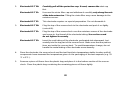
4. Instructions for wood moisture measurement ............................................................31
4.1 Handling of measuring electrodes for resistance measurement ......................................34
4.2 General information on wood moisture measurement .....................................................38
4.3 Handling of active electrode MH 34 .................................................................................42
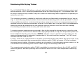
4.4 Monitoring kiln drying timber ............................................................................................43
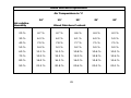
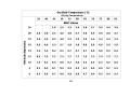
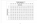
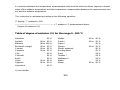
4.5 Conversion table EMC/wet bulb depression ....................................................................50
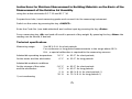
5. Instructions for structural moisture measurement .....................................................52
5.1 Handling of measuring electrodes for resistance measurement ......................................55
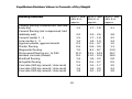
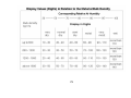
5.2 Table of equilibrium moisture values ................................................................................61
5.3 Handling of active electrodes ...........................................................................................67
5.4 Structural moisture measurement on the basis of
air humidity measurement ................................................................................................75
6. Air humidity measurement and determination of dew point .....................................79
6.1 Handling of air humidity probes ........................................................................................82
6.2 Calibrating instructions for air humidity probes ................................................................87
7. Instructions for temperature measurement .................................................................91
7.1 Handling of the active electrodes RF-T ............................................................................93
7.2 Handling of Pt 100 temperature probes ...........................................................................94
7.3 Infra-red temperature measurement ................................................................................99
3

8. Measuring electrodes and other accessory
8.1 Measuring electrodes for wood moisture measurement.................................................105
8.2 Measuring electrodes for structural moisture measurement ..........................................107
8.3 Air humidity sensors .......................................................................................................111
8.3 Temperature probes .......................................................................................................116
8.4 Other accessory .............................................................................................................118
8.5 Accessory for data transmittal ........................................................................................120
8.6 Accessory for monitoring kiln drying ..............................................................................122
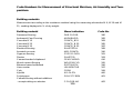
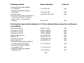
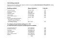
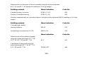
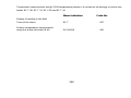
9. Code numbers
9.1 - for structural moisture measurement ...........................................................................126
9.2 - for air humidity measurement ......................................................................................129
9.3 - for temperature measurement .....................................................................................130
10. Warranty conditions .....................................................................................................131
4

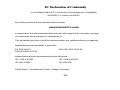
GANN Mess- u. Regeltechnik GmbH
EU Declaration of Conformity
as defined by machinery directive 89/392/EEC Annex II A
We hereby declare that the handheld moisture meter(s)
HYDROMETTE M-4050
supplied by us conform to the relevant safety- and health-related requirements of the appropriate EU
Directive as well as to the EU Directive on Electromagnetic Compability (89/336/EU) in version
93/31/EU. This declaration becomes void if the moisture meters are modified without our approval.
Applied harmonized standards in particular:
EN 55011/03.91 - DIN VDE 0875-11/07.92
DIN EN 50082-1/03.93
Applied national technical standards and specifications:
IEC 1000-4-2/1995 - IEC 1000-4-4/01.95
IEC 801-3/1984 - IEC 65A/77B
5

Important preliminary remarks
It is of great importance to carefully read and understand the following instructions. Warranty
claims for any damage caused by non-observance of these instructions cannot be accepted. In
no event will the manufacturer be liable for damages, including lost profits, lost savings or other
incidental or consequential damages or injury to persons arising out of the use of or inability to
use the product, even if the manufacturer has been advised of the possibility of such damages, or
for any claim by any other party.
All instructions for use of the product and its accessory should be strictly followed to avoid meas-
uring errors which frequently occur when trying to simplify the measuring procedure.
Make sure in any case by suitable means prior to drilling holes for measuring probes or before
driving electrode pins into walls, ceilings or floors that this happens away from power lines, water
pipings or other supply pipes.
Any use of the measuring instrument and its probes under unfavourable environment conditions
should be avoided. This could cause damage to the sensitive electronic circuitry of the meter and
its measuring probes.
Unfavourable environment conditions are among other things
-- too high an ambient air humidity (>90 %),
-- dampness,
-- dust and inflammable gases or vapours as well as air containing solvents,
-- ambient temperatures exceeding 50 °C,
-- ambient temperatures below the freezing point.
6

When using the measuring probes and connecting to or disconnecting them from the measuring
instrument do not use force and do not pull on the cable.
The measuring instrument, connecting cable and measuring probes must not be used or stored
in aggressive or air containing solvents.
Every printer connected to the measuring instrument must command the XON/XOFF require-
ments.
It should be noticed that measurements using the active electrodes B 50 and B 60 have always
to be taken with the meter set for battery operation. In case of mains operation the measuring
field can be changed what may result in measuring errors.
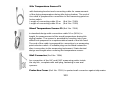
Static Electricity - At low air humidity circumstances such as friction during timber handling or
highly insulated surroundings may cause static electricity of very high voltages. This may result
not only in fluctuating or negative readings, but can also destroy transistors and ICs used in
manufacturing the moisture meter.
The operator too may contribute by his clothing or shoes made of man-made fibre to build up a
static charge. The results can markedly improved, if the operator stands perfectly still and avoids
moving the meter and the measuring cable while taking the reading.
Frozen wood with moisture content in excess of 20 % cannot be measured.
The information and tables on admissible or usual moisture conditions as well as the general
terms and definitions contained in the instructions were taken from the specialist literature. The
manufacturer or supplier of the measuring instrument cannot be held responsible for the correct-
ness of this information. The conclusions to be drawn from the measurement results by each
7

user are governed by the individual circumstances and experiences and knowledge gained in
the course of his professional practice.
The measuring instrument meets the stronger demands laid down in class B of the pertinent
regulations for interference emission and may, therefore, be used also in living areas.
The measuring instrument and its standard and optional accessory must only be used as de-
scribed in this manual.
In view of the electromagnetic compatibility and the reliability of measurement, only the standard
and optional accessory described in this manual must be used with the measuring instrument.
8

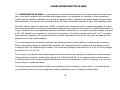
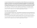
GANN HYDROMETTE M 4050
The HYDROMETTE M 4050 is a microprocessor operated instrument for measurement of wood mois-
ture, structural moisture, air humidity and temperature. It is designed for storage of these measure-
ments and for statistic evaluation according to medium value, highest and lowest reading and for stan-
dard deviation. The meter can memorize up to 30 series of measurements of up to 100 readings each.
Along its upper edge the meter has a BNC connector for connection of the measuring probes for mois-
ture measurements in wood and set building materials according to the resistance method electrode, a
7-pin connector for the temperature probes and active electrodes, a socket for a power supply unit and
a RS 232 interface connector for connection of a printer or for data transfer into an AT or XT compati-
ble personal computer. All entries take place via the membrane-covered 21-key pad; all data are dis-
played on a 4-line matrix display.
The measurement of structural moisture can be performed by three different measuring procedures.
When using the resistance method the readings are displayed direct in percent of dry weight and ac-
cording to the CM measuring procedure. The measuring ranges extend from 0.5 to 25 % of dry weight
and from 0.5 to 12 % CM.
The second, non-destructive measuring method is based on the capacity or dielectric constant meas-
uring principle using the active electrodes B 50, B 60 and MB 35. The measurement is performed in
scanning mode and reveals moisture distribution and concentrations in walls or ceilings, e.g. ascend-
ing moisture or water damages.
The third measuring method provides measurement of air humidity in a bore hole. The readings are
converted into percent of dry weight according to definite curves (sorptions isothermes).
9

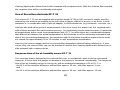
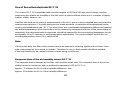
For measurement of the air relative humidity as well as the air temperature and the dew point, the op-
tionally available active electrodes RF-T 28, RF-T 31, RF-T 32 and RF-T 36 can be used with the Hy-
dromette M 4050.
For temperature measurement in solid materials, liquids, air and flue gas a wide range of PT 100 tem-
perature probes in 4-conductor design are available.
The ram-in electrode M 18 and the drive-in electrode M 20 finally are provided for wood moisture
measurement in the range between 5 and 100 % m.c. The additionally available active electrode MH
34 is exclusively designed for measuring coniferous wood with a moisture content between 40 and
200 % m.c. The wood temperature affecting the accuracy of measurement can be compensated either
by manually entering the wood temperature or, in case of measurements during kiln drying timber,
automatically by means of a temperature probe.
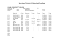
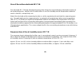
When printing out memorized measuring values, the printouts show the code number of the respective
building material or species of wood, the type of material, in case of wood moisture values also the en-
tered or measured temperature as well as date and time of measurement. All memory positions can
be erased at will and reused for new measurements. By means of the plus and minus keys the indi-
vidual memory positions can be called up at any time.
10

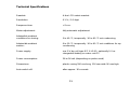
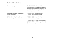
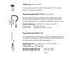
Technical Specifications
Readout: 4-line LCD matrix readout
Resolution: 0.1 % / 0.1 digit
Response time: < 2 sec.
Meter adjustment: fully automatic adjustment
Admissible ambient
conditions for storing: 5 to 40 °C, temporarily -10 to 60 °C not condensing
Admissible ambient 0 to 50 °C, temporarily -10 to 60 °C not conditions for op-
eration: condensing
Power supply: one 9 V dry cell type IEC 6 LR 61, optionally 9 V re-
chargeable battery or mains unit 12
Power consumption: 26 to 36 mA (depending on probe used)
Dimensions: plastic casing 190 mm long, 116 mm wide 56 mm high.
Auto-switch-off: after approx. 30 seconds.
11

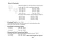
Measuring Ranges
Wood Moisture: between 5 and 100 % m.c. with ram-in electrode M 18 and drive-in
electrode M 20,
between 40 and 200 % m.c. with live electrode MH
34, 5 to 30 % m.c. if used in the manufacture of laminated beams ac-
cording to DIN 1052 using code No. 373 and the M 18 and M 20 elec-
trodes.
Structural Moisture: 0.3 to 25 % of dry weight or 0.3 to 12 % CM for measurements ac-
cording to the resistance method and input of code number, or
0 to 80 digits according to the resistance method (scanning range), or
0 to 199 digits for non-destructive measurement with live electrodes
B 50 and B 60 (scanning range), or
0.3 to 8.5 % CM for non-destructive measurement with live electrodes
B 50 and B 60 and input of code number, or
2 to 8 % of dry weight for non-destructive measurements of concrete
surfaces with live electrode MB 35 and input of code number, or
0.3 to 6.5 % CM for non-destructive measurements of concrete sur-
faces with live electrode MB 35 and input of code number, or
0.2 to 3.7 % of dry weight, direct reading of converted sorptions iso-
thermes.
12

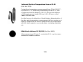
Measuring Ranges
Air Temperature: 5 to 98 % R.H. using live electrodes RF-T 28, RF-T 31, RF-T 32 and
RF-T 36.
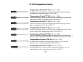
Temperature: -30 to 170 °C depending on PT temperature probe used or
0 to 170 °C with infrared temperature probe IR 40.
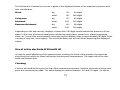
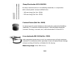
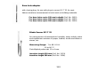
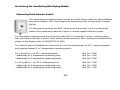
Battery Check
If battery voltage drops below 7.5 V, »WARNING - BATTERY VOLTAGE TOO LOW« appears on the
LCD readout when the meter is switched on. In general a few measurements are still possible but the
battery should be replaced or recharged soon. The cover of the battery compartment can be lifted by
means of a screw driver or a coin inserted into the slot.
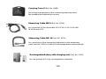
Power Source
The meter is fitted, as standard equipment, with a 9 V dry cell IEC 6 LF 22 or IEC 6 LR 61. It is rec-
ommended to use alkaline batteries.
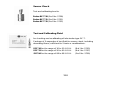
A rechargeable nickel-cadmium battery can be fitted optionally. It can be recharged from any AC light-
ing supply socket by means of the charging unit supplied with this special battery. Charging time is
about 12 hours at 230 V.
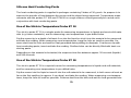
Mains Operation
The meter can optionally be equipped with a power supply unit which is particularly recommended for
data transfers to a printer or PC.
13

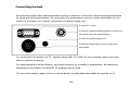
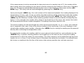
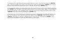
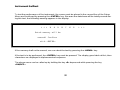
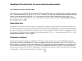
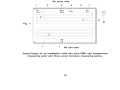
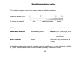
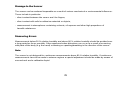
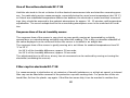
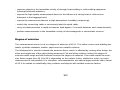
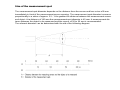
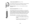
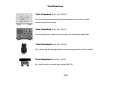
Connecting Sockets
Along the top edge of the instrument there are four sockets for connection of the measuring electrodes
for wood and structural moisture, for connection of a temperature sensor or active electrodes, for con-
nection of a printer or PC and for connection of a power supply unit.
Printer/PC socket
Socket for measuring electrodes for wood a
structural moisture measurement nd
Socket for power supply unit
Socket for temperature sensor and active
electrodes
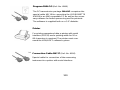
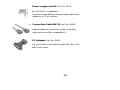
For connection of a printer or a PC, special cables (MK 17 or MK 19) are necessary which are avail-
able as optional accessory.
For measurement of wood moisture, structural moisture, air humidity or temperature, all measuring
electrodes of the GANN HYDROMETTE program can be used.
The use of the power supply unit is recommended for lengthy data transmittals to a printer or PC.
14

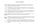
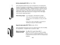
Function of the keys
ON/OFF Key - Upon pressing this key the main menu appears. At the position of the
blinking cursor code number of the material to be measured ensuring automatic species
correction of the readings is to be entered.
Numerical Keys - These keys serve for all numerical inputs such as code numbers, the
value for wood temperature compensation or the number of the series of measurements
under which the readings are to be stored.
Measuring Key - After driving the pins of the measuring electrode into the material to be
measured or application of any other measuring probe, the reading will be displayed on the
right hand side of the top line upon pressing this key.
»ENTER« Key - All entries including selections made via the »ARROW Keys« must be
verified by pressing this key. The processor will only then accept the entry.
Memory Key - By pressing the memory key, the reading displayed including the measured
or entered wood temperature and the date and time can be stored under a series number (1
to 30) and the individual number of the reading (1 to 100).
Minus Key - This key serves for the entry of a negative temperature value as well as for
back browsing in the register of materials in alphabetical sequence and for back browsing in
the register of charge numbers and the numbers of individual readings for viewing of stored
readings.
15

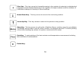
Plus Key - This key serves for forward browsing in the register of materials in alphabetical
sequence and for forward browsing in the register of charge numbers and the numbers of
individual readings for viewing of stored readings.
Arrow Down Key - This key serves to move to the next entry position.
Arrow Up Key - This key serves to return to the previous entry position.
Menu Key - This key serves to call up the »Statistics Menu« and the menu for cancellation
of readings stored under a specific series number, for dialogue with the PC and for printing
of the stored readings by means of a printer connected to the meter.
Print Key - To start printing of the last moisture and temperature measurement including
time and date of measurement.
Period Key.
16

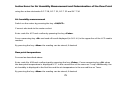
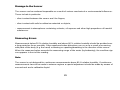
Setting the Instrument to Work
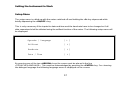
Setup Menu
The setup menu is called up with the meter switched off and holding the »0« key depressed while
briefly depressing the »ON/OFF« key.
This is only necessary if the inputs for date and time and the baud rate have to be changed or if all
data memorized shall be deleted using the selftest function of the meter. The following setup menu will
be displayed:
Sprache / Language [ * ]
Selftest [ * ]
Baudrate [ * ]
Date / Time [ * ]
By pressing one of the two »ARROW« keys the cursor must be placed in the line
»SPRACHE/LANGUAGE«. This must be acknowledged by pressing the »ENTER« key. For choosing
the dialogue language the following language menu is displayed on the screen:
17

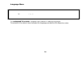
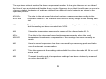
Language Menu
UK [ * ]
The HYDROMETTE M 4050 is available with software in different languages.
The asterisk in the above menu indicates the language provided for the respective meter.
18

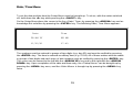
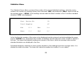
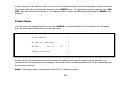
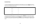
Date / Time Menu
To set the date and the time the Setup Menu must be brought up. To do so, with the meter switched
off, hold down the »0« key while pressing the »ON/OFF« key.
On the Setup Menu place the cursor in the line »Date / Time« by pressing the »ARROW« key and ac-
knowledge this selection by pressing the »ENTER« key. The following Date / Time Menu appears:
Date Time
DD MM YY HH MM
01/02/91 07:43
The numbers must be entered in groups of two digits (e.g. day 02) and must be verified by pressing
the »ENTER« key. The time is entered as military time (e.g. 15:24). All of these entries must be made
in groups of two digits and each entry of two numbers must be verified by pressing the »ENTER« key.
The cursor can be moved to the left with the »ARROW UP« key and to the right with the »ARROW
DOWN« key. Upon completion of the date and time entry, the »Setup Menu« can be brought up by
pressing the »MENU« key once, and the »Main Menu« is brought up by pressing the »MENU« key
twice.
19
Page is loading ...
Page is loading ...
Page is loading ...
Page is loading ...
Page is loading ...
Page is loading ...
Page is loading ...
Page is loading ...
Page is loading ...
Page is loading ...
Page is loading ...
Page is loading ...
Page is loading ...
Page is loading ...
Page is loading ...
Page is loading ...
Page is loading ...
Page is loading ...
Page is loading ...
Page is loading ...
Page is loading ...
Page is loading ...
Page is loading ...
Page is loading ...
Page is loading ...
Page is loading ...
Page is loading ...
Page is loading ...
Page is loading ...
Page is loading ...
Page is loading ...
Page is loading ...
Page is loading ...
Page is loading ...
Page is loading ...
Page is loading ...
Page is loading ...
Page is loading ...
Page is loading ...
Page is loading ...
Page is loading ...
Page is loading ...
Page is loading ...
Page is loading ...
Page is loading ...
Page is loading ...
Page is loading ...
Page is loading ...
Page is loading ...
Page is loading ...
Page is loading ...
Page is loading ...
Page is loading ...
Page is loading ...
Page is loading ...
Page is loading ...
Page is loading ...
Page is loading ...
Page is loading ...
Page is loading ...
Page is loading ...
Page is loading ...
Page is loading ...
Page is loading ...
Page is loading ...
Page is loading ...
Page is loading ...
Page is loading ...
Page is loading ...
Page is loading ...
Page is loading ...
Page is loading ...
Page is loading ...
Page is loading ...
Page is loading ...
Page is loading ...
Page is loading ...
Page is loading ...
Page is loading ...
Page is loading ...
Page is loading ...
Page is loading ...
Page is loading ...
Page is loading ...
Page is loading ...
Page is loading ...
Page is loading ...
Page is loading ...
Page is loading ...
Page is loading ...
Page is loading ...
Page is loading ...
Page is loading ...
Page is loading ...
Page is loading ...
Page is loading ...
Page is loading ...
Page is loading ...
Page is loading ...
Page is loading ...
Page is loading ...
Page is loading ...
Page is loading ...
Page is loading ...
Page is loading ...
Page is loading ...
Page is loading ...
Page is loading ...
Page is loading ...
Page is loading ...
Page is loading ...
Page is loading ...
Page is loading ...
-
 1
1
-
 2
2
-
 3
3
-
 4
4
-
 5
5
-
 6
6
-
 7
7
-
 8
8
-
 9
9
-
 10
10
-
 11
11
-
 12
12
-
 13
13
-
 14
14
-
 15
15
-
 16
16
-
 17
17
-
 18
18
-
 19
19
-
 20
20
-
 21
21
-
 22
22
-
 23
23
-
 24
24
-
 25
25
-
 26
26
-
 27
27
-
 28
28
-
 29
29
-
 30
30
-
 31
31
-
 32
32
-
 33
33
-
 34
34
-
 35
35
-
 36
36
-
 37
37
-
 38
38
-
 39
39
-
 40
40
-
 41
41
-
 42
42
-
 43
43
-
 44
44
-
 45
45
-
 46
46
-
 47
47
-
 48
48
-
 49
49
-
 50
50
-
 51
51
-
 52
52
-
 53
53
-
 54
54
-
 55
55
-
 56
56
-
 57
57
-
 58
58
-
 59
59
-
 60
60
-
 61
61
-
 62
62
-
 63
63
-
 64
64
-
 65
65
-
 66
66
-
 67
67
-
 68
68
-
 69
69
-
 70
70
-
 71
71
-
 72
72
-
 73
73
-
 74
74
-
 75
75
-
 76
76
-
 77
77
-
 78
78
-
 79
79
-
 80
80
-
 81
81
-
 82
82
-
 83
83
-
 84
84
-
 85
85
-
 86
86
-
 87
87
-
 88
88
-
 89
89
-
 90
90
-
 91
91
-
 92
92
-
 93
93
-
 94
94
-
 95
95
-
 96
96
-
 97
97
-
 98
98
-
 99
99
-
 100
100
-
 101
101
-
 102
102
-
 103
103
-
 104
104
-
 105
105
-
 106
106
-
 107
107
-
 108
108
-
 109
109
-
 110
110
-
 111
111
-
 112
112
-
 113
113
-
 114
114
-
 115
115
-
 116
116
-
 117
117
-
 118
118
-
 119
119
-
 120
120
-
 121
121
-
 122
122
-
 123
123
-
 124
124
-
 125
125
-
 126
126
-
 127
127
-
 128
128
-
 129
129
-
 130
130
-
 131
131
-
 132
132
-
 133
133


GANN GA-M4050 Owner's manual
- Type
- Owner's manual
- This manual is also suitable for
Ask a question and I''ll find the answer in the document
Finding information in a document is now easier with AI
Related papers


Other documents
-
YSI 6-Series Owner's manual
-
-
-
Omega PHB-215, PHB-220, PHB-225, PHB-250 Owner's manual
-
sauermann Si-CA 8500 User manual
-
 Thermo Fisher Scientific Orion Versa Star Pro User manual
-
 Roxar MultiCorr MKII Corrosion Meter and Data Acquisition Unit Owner's manual
-
-
-
ADWA AD1000 User manual

