4
30" ELECTRIC SLIDE-IN RANGE INSTALLATION INSTRUCTIONS
Important Notes to the Installer
1. Read all instructions contained in these installation
instructions before installing range.
2. Remove all packing material from the oven
compartments before connecting the electrical supply
to the range.
3. Observe all governing codes and ordinances.
4. Be sure to leave these instructions with the consumer.
Important Note to the Consumer
Keep these instructions with your owner's guide for future
reference.
IMPORTANT SAFETY
INSTRUCTIONS
Cold temperatures can damage the
electronic control. When using the appliance for the first
time, or when the appliance has not been used for an
extended period of time, be certain the unit has been in
temperatures above 32°F (0°C) for at least 3 hours
before turning on the power to the appliance.
• Be sure your range is installed and grounded
properly by a qualified installer or service
technician.
• This range must be electrically grounded in
accordance with local codes or, in their absence,
with the National Electrical Code ANSI/NFPA No.
70—latest edition in United States or with CSA
Standard C22.1, Canadian Electrical Code, Part 1 in
Canada.
• The installation of appliances designed for
manufactured (mobile) home installation must conform
with Manufactured Home Construction and Safety
Standard, title 24CFR, part 3280 [Formerly the Federal
Standard for Mobile Home Construction and Safety,
title 24, HUD (part 280)] or when such standard is not
applicable, the Standard for Manufactured Home
Installation 1982 (Manufactured Home Sites,
Communities and Setups), ANSI Z225.1/NFPA 501A-
latest edition, or with local codes in United States and
with CAN/CSA-Z240 MH in Canada.
• Make sure the wall coverings around the range
can withstand the heat generated by the range.
• Before installing the range in an area covered
with linoleum or any other synthetic floor
covering, make sure the floor covering can
withstand heat at least 90°F (32.2°C) above room
temperature without shrinking, warping or
discoloring. Do not install the range over carpeting
unless you place an insulating pad or sheet of ¼" (0.64
cm) thick plywood between the range and carpeting.
Never leave children alone or
unattended in the area where an appliance is in use.
As children grow, teach them the proper, safe use of all
appliances. Never leave the oven door open when the
range is unattended.
Stepping, leaning or sitting on the
door or drawer of this range can result in serious
injuries and can also cause damage to the range.
• Do not store items of interest to children in the
cabinets above the range. Children could be seriously
burned climbing on the range to reach items.
• To eliminate the risk of burns or fire by reaching
over heated surface units, cabinet storage space
above the surface unit should be avoided. If
cabinet storage is to be provided the risk can be reduce
by installing a range hood that project horizontally a
minimum of 5 inches beyond the bottom of the
cabinet.
• Do not use the oven as a storage space. This
creates a potentially hazardous situation.
• Never use your range for warming or heating the
room. Prolonged use of the range without adequate
ventilation can be dangerous.
• Do not store or use gasoline or other flammable
vapors and liquids near this or any other
appliance. Explosions or fires could result.
• Reset all controls to the "off" position after using
a programmable timing operation.
FOR MODELS WITH SELF-CLEAN FEATURE:
• Remove broiler pan, food and other utensils
before self-cleaning the oven. Wipe up excess
spillage. Follow the precleaning instructions in the
Owner's Guide.
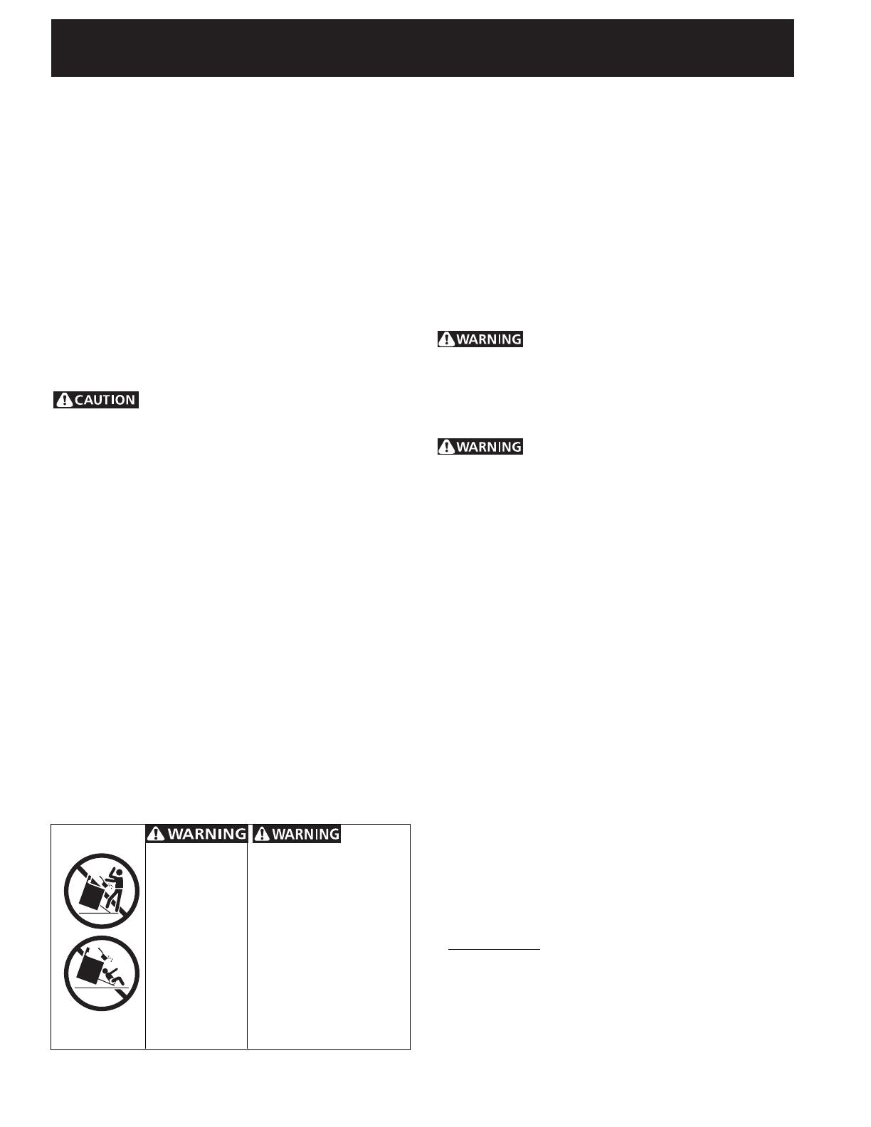
TO REDUCE
THE RISK OF TIPPING OF
THE RANGE, THE RANGE
MUST BE SECURED BY
PROPERLY INSTALLED ANTI-
TIP BRACKET(S) PROVIDED
WITH THE RANGE. TO
CHECK IF THE BRACKET(S)
IS INSTALLED PROPERLY,
GRASP THE TOP REAR
EDGE OF THE RANGE AND
CAREFULLY TILT IT
FORWARD TO MAKE SURE
THE RANGE IS ANCHORED.
• ALL RANGES
CAN TIP.
• INJURY TO
PERSONS
COULD
RESULT.
• INSTALL ANTI-
TIP DEVICE
PACKED WITH
RANGE.