Haier 1U12LC2VHA Installation guide

Category
Split-system air conditioners
Type
Installation guide
Ductless Split Air Conditioner
Installation Manual
Indoor
AW12LC2VHA
AW18LC2VHA
AB12SC2VHA
AB18SC2VHA
AD12SL2VHA
AD18SL2VHA
Outdoor
1U12LC2VHA
1U18LC2VHA
1U12LC2VHA
1U18LC2VHA
1U12LC2VHA
1U18LC2VHA
Outdoor Unit Installation and Indoor Unit Installation – Wall Mount . . . . . . . . . . . . . . . . . 1-8
Indoor Unit Installation - Cassette
. . . . . . . . . . . . . . . . . . . . . . . . . . . . . . . . . . . . . . . . . .
9-14
Indoor Unit Installation - Slim Duct. . . . . . . . . . . . . . . . . . . . . . . . . . . . . . . . . . . . . . . . . .15-20
Table of Contents
IN
S
T
AL
L
A
TION
24k
F
or:
09k
Required Tools for Installation
Procedure for Selecting the Location
than 10ft away depending on radio wave
conditions.)
Drill
Wire Snipper
Hole Saw 2 3/4
Vacuum pump
Soap-and-water solution or gas leakage
detector
Torque wrench
17mm, 22mm, 26mm
Tubing cutter
Flaring tool
Razor knife
Measuring tape
Level
Micron gauge
Nitrogen
Mini-Split AD-87 Adapter (1/4” to 5/16”)
A - Non-adhesive Tape
B - Adhesive Tape
C - Saddle (L.S.) with screws
D - Electrical wiring
E - Drain hose (Included)
F - Insulation
G - Piping hole cover (Included)
Choose a place solid enough to bear the
weight and vibration of the unit and where
the operation noise will not be amplified.
Choose a location where the hot air
discharged from the unit or the operation
noise and will not cause a nuisance to the
neighbors of the user.
There must be sufficient space for
carrying the unit into and out of the site.
There must be sufficient space for air
passage and no obstructions around the
air inlet and air outlet.
The site must be free from the possibility
of flammable gas leakage in a nearby
place.
Locate the unit to avoid noise and
discharged hot air will not annoy the
neighbors.
Install units, power cords and inter-unit
cables at least 10ft away from television
and radio sets. This is to prevent
interference to images and sounds.
(Noise may be heard even if they are more
Since drain flows out of the outdoor unit,
do not place anything under the unit that
must be kept away from moisture.
Note:
1) Cannot be installed hanging from ceiling
or stacked.
2)
If installing on a high place such as a roof,
with a fence or guard rail around it.
3)
If there is a potential for accumulated
snow to block the air inlet or heat ex-
changer, install the unit on a higher base.
4) R-410A refrigerant is a safe, nontoxic and
nonflammable refrigerant. However, if
there is a concern about a dangerous level
of refrigerant concentration in the case of
refrigerant leakage, add extra ventilation.
5)
Avoid installing the outdoor unit where
corrosive gases, such as sulfur oxides, am-
monia, and sulfurous gas, are produced. If
unavoidable, consult with an installation
specialist about using a corrosion-proof or
anti-rust additive to protect the unit coils.
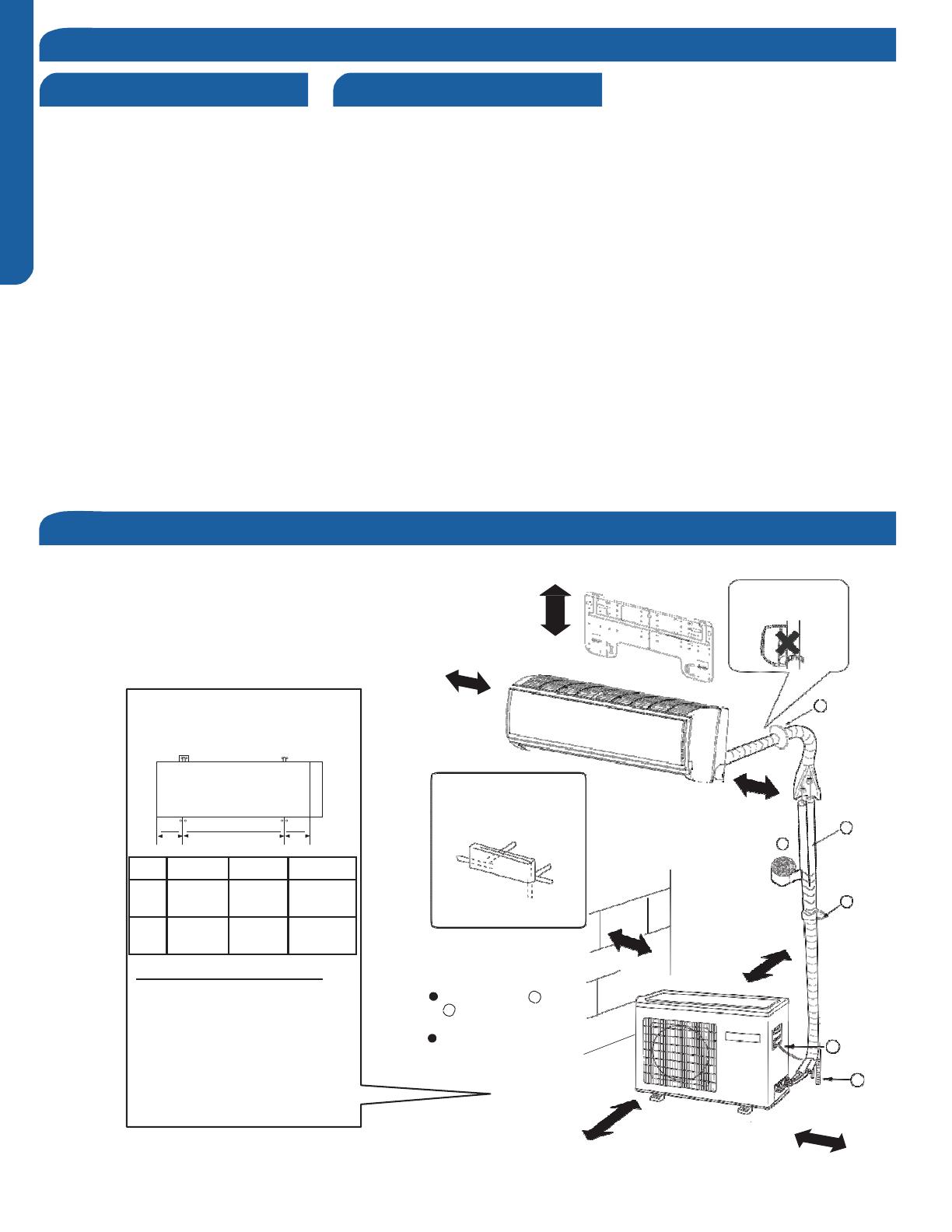
This picture is for reference only. Your product may look
different. Read this manual before installation. Explain the
operation of the unit to the user according to this manual.
The models adopt HFC free refrigerant R410A
more than 4 in.
Attention must be paid to
the rising up of drain hose
Outdoor unit mounting
dimensions (Unit: mm/inch)
more than
G
4 in.
Arrangement of piping
directions
Rear left
Left
Rear
right
more than 4 in.
F
A
Mounting the Outdoor Unit
Mount the unit to concrete or a block
Below
The marks from
A
to
Right
more than 8 in.
C
more than
6 in.
with bolts (10mm) and nuts firmly and
horizontally.
When mounting the unit to a wall or
roof, take strong winds and other
environmental conditions into
consideration when securing.
If vibrations effect the house, mount
the unit using a vibration-proof mat.
G
in the figure are the
parts numbers.
The distance between
the indoor unit and the
D
floor should be more
than 6.5 ft.
E
more than
24 in.
more than 10 in.
Clearances of Indoor and Outdoor Units
Step 1 - Preparation
ENGLISH
For:
12k 18k
Z
X
Y
X
X
Y
Z
12k
5 1/2”
140
mm
19 11/16”
500
mm
10 1/16”
256
mm
18k
4 7/16”
113.5
mm
22 15/16”
583
mm
12 9/16”
319.5
mm
IN
S
T
AL
L
A
TION
P
AGE
3
Step 2 - Installation of the Indoor Unit
Attaching the Mounting Plate to the Wall
Using a stud sensor, locate and mark the stud positions in the
wall where the indoor unit is to be mounted.
Place the mounting plate on the wall in the desired location
taking into account the minimum clearances necessary for
proper operation.
Using a level, verify the mounting plate is horizontal and mark
the screw locations.
Screw the mounting plate to the wall.
The piping for the indoor unit may be routed to the unit from
one of several directions. Left, Left Rear, Right, Right Rear, or
Below (Illustration 1).
Knockouts are provided on the case for Left, Right, and Right
Below.
Drilling the hole through the wall for left rear or right rear
installation
Measure and mark the location where the piping hole is to be
drilled.
Drill the piping hole using a hole saw of the correct diameter.
Angle the drill with a downward pitch to the outside wall so
that the outside hole will be ¼” lower than the inside hole,
giving the hole the proper angle for condensate drainage.
Install the piping hole cover flange at the hole opening on the
inside wall.
NOTE: The cover flange may require modification to fit
properly behind the wall unit housing.
Step 2.1
Step 2.3
Step 2.6
Step 2.8A
Step 2.2
Step 2.4
Step 2.5B
Step 2.7
Step 2.8B
Bundle the refrigerant piping, drain piping and wiring with
tape and pass the bundle through the piping hole.
NOTE: When bundling the power cable, leave sufficient length
available in the indoor unit to make the connections to the
terminal block.
Illustration 1
2.8
Step 2.8A & 2.8B
Step
2.5A
2.7
Step 2.7
2.6
Step 2.6
2.5
Step 2.5A & 2.5B
2.4
Step 2.4
2.3
Step 2.3
2.2
Step 2.2
2.1
Step 2.1
Piping Exit Options
Rear left
Left
Rear
right
Right
Below
ENGLISH
IN
S
T
AL
L
A
TION
Step
2.9
Attaching Drain Elbow to Outdoor Unit
With the top of the indoor unit closer to the wall, hang the
indoor unit on the upper hooks of the mounting plate. Slide
the unit slightly side to side to verify proper placement of the
indoor unit on the mounting plate. Rotate the lower portion
of the indoor unit to the mounting plate, and lower the unit
onto the lower hooks of the mounting plate. (Illustration 2)
Verify the unit is secure.
Step 2.10
Slightly raise the entire unit vertically, pull the lower portion
of the unit off the lower hooks of the mounting plate and
away from the wall, then lift the upper portion of the unit off
the upper hooks of the wall plate.
mounting plate
Illustration 2
To make the electrical connections for the indoor unit, two
cover plates must be removed. Raise the front cover to
access the screws to remove these covers.
Access the four conductor cable through the cover plate
opening and make the wiring connections noting the wire
color used on each terminal. The color of each wire must
match the same positions on the terminal block of the
outdoor unit. (Illustration 3)
Step 2.11A
Step 2.11B
Failure to wire the system correctly may lead to improper
operation or component damage.
After the terminal block wiring is completed, replace both
cover plates.
Step 2.12
Indoor unit
Step 2.13A
3wire 14AWG
Control Wiring
Outdoor unit
Step 2.13B
Illustration 3
Power
Wiring
(Heat Pump models only)
If attaching the supplied drain elbow to the outdoor unit,
do so prior to attaching the refrigerant lines and wiring.
Extension piping to attach to this fitting is field supplied.
Step 3.1
Step 3.2
Remove the cover plate of the outdoor unit to expose the
terminal block connections.
3.2
Step - 3.2
Electrical Connections for the Outdoor Unit
2.11
Step - 2.11A & 2.11B
Electrical Connections for the Indoor Unit
2.10
Step - 2.10
2.9
Step 2.9
Mounting the Indoor Unit Onto the Wall Plate
3.1
Step - 3.1
2.13
Step - 2.13
2.14
Step - 2.14A & 2.14B
Step 3 - Installation of the Outdoor Unit
1
(
N
)
2
(L)
3
(
C
)
1
(
N
)
2
(
L)
3
(C)
ENGLISH
IN
S
T
AL
L
A
TION
P
AGE
5
3.3
St
ep
-
3.3
Connect the wiring for both the power source and indoor
wiring.
Wire the system according to applicable national / local
codes.
Verify that the wiring connections for the indoor unit match
wire for wire.
(1-1, 2-2, 3-3, Gnd-Gnd). Failure to wire the system correctly
ma
y
lead
t
o
improper
operation
or
component
damage.
Step
3.3
Step
3.4
3.4
St
ep
-
3.4
Replace
the
cover
plate.
St
ep
4
-
Int
erconnec
ting
t
he
Indoor
and
Out
door
Units
*See Steps 2.11 - 2.13 & 3.2 - 3.4 for connecting the
electrical.
The standard lineset length is 25ft. If the installation length is
different, adjust the refrigerant charge by .2 oz / ft. for the 9K,
12K, 18K, and 24K model. (Illustration 4)
Cut the lineset to length, flare and attach the piping to the
outdoor unit valves.
Torque the fittings to the specifications shown in the torque
chart.
Refrigerant piping connections for the mini-split system are
made utilizing flare connections. Follow standard practices
for creating pipe flares. When cutting and reaming the tubing,
use caution to prevent dirt or debris from entering the tubing.
Remember to place the nut on the pipe before creating the
flare.
To join the lineset piping together, directly align the piping
flare to the fitting on the other pipe, then slide the nut onto
the fitting and tighten. Misalignment may result in a leaking
connection.
Step 4.1
Half union
Flare nut
Illustration 4
Step 4.2
Two wrenches are required to join the flare connections, one
standard wrench, and one torque wrench. See Table 1 for the
specific torque per piping diameter.
Spanner
Torque wrench
Table 1
Step 4.3
4.2
Step - 4.2
4.1
Step - 4.1
Piping
CAUTION
Outdoor unit
B
Indoor unit
B
A
Indoor unit
A
Outdoor unit
Outdoor unit
Oil
trap
B
Indoor
unit
A
Max. Elevation: A Max
= 32ft / 10m (09k / 12k)
= 50ft / 15m (18k / 24k)
In case the height of A is more than
15ft / 5m, an oil trap should be
installed every 16-23ft /5-7m
Max. Length: B Max
= 50ft / 15m (09k / 12k)
= 80ft / 25m (18k / 24k)
2.17
Step - 4.3
Forced fastening without careful centering may
damage the threads and cause a leakage of gas.
ENGLISH
Pipe Diameter(
ǿ
) Fastening torque
Liquid side6.35mm(1/4") 18N.m/13.3Ft.lbs
Liquid/Gas side9.52mm(3/8")
42 N.m/30.1Ft.lbs
Gas side 12.7mm(1/2") 55N.m/40.6Ft.lbs
Gas side 15.88mm(5/8") 60 N.m/44.3Ft.lbs
IN
S
T
AL
L
A
TION
Hazard of Explosion! Never use an open flame to detect gas
leaks. Explosive conditions may occur. Use a leak test solution
or other approved methods for leak testing. Failure to follow
recommended safe leak test procedures could result In death
or serious injury or equipment or property damage.
Use only dry nitrogen with a pressure regulator for
pressurizing unit. Do not use acetylene, oxygen or
compressed air or mixtures containing them for pressure
testing. Do not use mixtures of a hydrogen containing
refrigerant and air above atmospheric pressure for pressure
testing as they may become flammable and could result in
an explosion. Refrigerant, when used as a trace gas should
only be mixed with dry nitrogen for pressurizing units. Failure
to follow these recommendations could result in death or
serious injury or equipment or property damage.
Using a tank of nitrogen with attached regulator, charge the
system with 500 PSIG of dry nitrogen. Use adapter AD-87
(field supplied) to connect to the valve. Check for leaks at the
flare fittings using soap bubbles or other detection methods.
If a leak is detected, repair and recheck. If no leaks are
detected, proceed to evacuate the system.
Step 5.1
Step 5.3
Step 5.2
Step 5.4A
Attach a manifold gauge, micron gauge, and vacuum pump
to the suction line port using adapter AD-87 (field supplied).
(Illustration 5)
Evacuate the system to 350 microns.
Close the vacuum pump valve and check the micron
gauge. If the gauge rises above 500 microns in 60 seconds,
evacuation is incomplete or there is a leak in the system. If
the gauge does not rise above 500 microns in 60 seconds,
evacuation is complete.
Step 5.5B
Step 5.6
Remove the adapter and hose connection from the suction
line port, and replace the cap.
Remove the cap from the liquid line valve. Using the hex
wrench, open the valve, then replace and tighten the cap.
Remove the cap from the suction line valve. Using the hex
wrench, open the valve, then replace and tighten the cap.
Illustration 5
Wrap the lineset, drain line, and wiring starting at the bottom
of the bundle with an overlap type wrap, concluding at the
5.6
Step - 5.6
5.5
Step - 5.5A & 5.5B
5.4
Step - 5.4A & 5.4B
5.3
Step - 5.3
5.1
Step - 5.1
Leak Test
Step
5.4B
Step
5.5A
System Evacuation
Step 5 - Leak Test and Evacuation
5.2
Step - 5.2
ENGLISH
IN
S
T
AL
L
A
TION
P
AGE
7
piping
hole.
Use
a
sealant
to
seal
the
piping
hole
opening
to prevent weather elements from entering the building.
(Illustration
6)
Less
than
5cm
Verify
the
condensate
drain
line
has
a
constant
pitch
downward for proper water flow. There should be no kinks
or rises in the tubing which may cause a trapping effect
resulting
in
the
f
ailure
of
the
condensate
t
o
exit
the
piping.
It
becomes
high midway.
The end is
imm
-
ersed in water.
It
waves.
The gap with
the
There is the bad
ground is too small
smell
from
a sewer
Illustration
6
St
ep
6
-
Charging
See Steps 5.2
-
5.5 for evacuating the system prior to
charging.
T
he
standard
lineset
length
is
25ft.
If
the
installation
S
y
s
t
em
T
e
s
t
length is different, adjust the refrigerant charge by .2 oz / ft.
for the 9K, 12K, 18K, and 24K model. (Step 4
-
Illustration 4)
Please kindly explain to our customers how to operate
through the instruction manual.
This product contains fluorinated greenhouse gases covered
by the Kyoto Protocol. Do not vent into the atmosphere.
Refrigerant type: R410A
GWP* value: 1975
GWP = global warming potential
Please fill in with indelible ink,
1 the factory refrigerant charge of the product
2 the additional refrigerant amount charged in the field and
1+2 the total refrigerant charge on the refrigerant charge
label supplied with the product.
The filled out label must be adhered in the proximity of the
product charging port (e.g. onto the inside of the stop valve
cover).
A - contains fluorinated greenhouse gases covered by the
Kyoto Protocol
B - factory refrigerant charge of the product: see unit name
plate
C - additional refrigerant amount charged in the field
D - total refrigerant charge
E - outdoor unit
F
-
refrigerant cylinder and manifold for charging
Put check mark
in boxes
No gas leak from linesets?
Are the linesets insulated properly?
Are the connecting wirings of indoor and outdoor firmly
inserted to the terminal block?
Is the connecting wiring of indoor and outdoor firmly
fixed?
Is condensate draining correctly?
Is the ground wire securely connected? Is the indoor unit
securely fixed?
Is power source voltage correct according to local code?
Is there any noise?
Is the lamp normally lighting?
Are cooling and heating (when in heat pump) performing
normally?
Is the operation of room temperature sensor normal?
Contains
fluorinated
gree
nhouse
gases
covered by the Kyoto Protocol
A
R410A
2
1
1=
oz
B
2=
oz
C
1+2=
oz
D
F
E
Check Items for Test Run
Refrigerant Charge Label
ENGLISH
IN
S
T
AL
L
A
TION
Using the OPERATING INSTRUCTIONS, explain to the user how to use the air conditioner (the remote controller, removing
the air filters, placing or removing the remote controller from the remote controller holder, cleaning methods, precautions for
operation, etc.)
Recommend that the user read the OPERATING INSTRUCTIONS carefully.
Model Name
Outdoor 1U12LC2VHA 1U18LC2VHA
Indoor AW12LC2VHA AW18LC2VHA
Operating Range
Cooling °F(°C)
0~115(-18~46)
0~115(-18~46)
Heating °F(°C)
5~75(-15~24)
5~75(-15~24)
Power Supply
Voltage, Cycle, Phase V/Hz/-
208-230/60/1
208-230/60/1
Outdoor Unit
Compressor Type
DC Inverter Driven Rotary
Maximum Fuse Size A
15
25
Minimum Circuit Amp A
15
15
Refrigerate Line
Connections
Flare
Flare
Liquid O.D. in
1/4
1/4
Suction O.D. in
3/8
1/2
Factory Charge Oz
R410A / 42.32
R410A / 45.86
Maximum Line Length Ft / m
50/15
83/25
Maximum Height Ft / m
33/10
50/15
The outdoor unit should be installed at least ½ mile away from the salt water, including seacoasts and inland waterways. If
the unit installed from
1/2
mile to 5 miles away from the salt water, including seacoasts and inland waterways, please follow the
installation instruction below.
Install the outdoor unit in a place (such as near buildings etc.) where it can be protected from sea breeze which can damage
the outdoor unit.
If you cannot avoid installing the outdoor unit by the seashore, construct a protection wall around it to block the sea breeze.
A protection wall should be constructed with a solid material such as
Protection walls
Sea breeze
ODU
concrete to block the sea breeze and the height and the width of the wall
should be 1.5 times larger than the size of the outdoor unit. Also, secure
over 28 in (700mm) between the protection wall and the outdoor unit for
exhausted air to ventilate.
Sea
ODU
Install the outdoor unit in a place where water can drain smoothly.
If you cannot find a place satisfying above conditions, please contact manufacturer. Make sure to clean the sea water and the
dust on the outdoor unit heat exchanger
Sea
b
r
ee
ze
ODU
Sea
ODU
Sea
breeze
ODU
Sea
Section 9 - Seacoast Application
Section 8 - System Specifications
Section 7 Explaining Operation to the End User
ENGLISH
IN
S
T
AL
L
A
TION
P
AGE
9
Indoor Unit Installation - Cassette
The Cassette Indoor Air Handler ships consists of a cassette
assembly and operational louver. The Cassette Indoor Unit
is operated via a factory supplied remote control. Wired
controller is optional.
The Cassette unit will install between standard dropped
ceiling grids. It is mounted using threaded rods that fit into
brackets that are located at all four corners of the cassette
assembly.
The Cassette unit receives 230 volt line voltage from a
connection at the outdoor condensing unit. There is no
requirement for independent line voltage connections.
The cassette unit has a built in condensate pump and
associated float switch that manages the operation of
the condensate pump. A flexible hose is included with the
Cassette unit. This hose connects the cassette condensate
drain outlet to the buildings condensate drain system.
The motorized louver is controlled via the remote control.
The louver has indicator lights that communicate function
and diagnostic information to the user and service technician.
Optional fresh air can be piped into the cassette assembly.
The knockout is located on the side of the cassette assembly.
If fresh air is desired, be certain to filter the air prior to it
entering the cassette. A 4galvanized pipe should be used to
pipe in the fresh air.
Included with the cassette unit is factory provided insulating
tape. This tape should be placed over the refrigerant piping
connections at the indoor unit to prevent sweating.
Wired Controller is
Optional
Built-in Condensate
Pump and Float Switch
Factory Supplied
Remote
Outside Air
Mounting Hangers
Indoor
AB12SC2VHA
AB18SC2VHA
Rated Cooling Capacity Btu/hr
12,000
18,000
Rated Heating Capacity Btu/hr
13,000
19,000
Voltage, Cycle, Phase V/Hz/-
208-230/60/1
208-230/60/1
Fan Speed Stages
5+Auto
5+Auto
Airflow (Turbo/High/Med/Low/
Quiet) CFM
410/365/305/265/205
470/410/365/295/252
Motor Speed (Turbo/High/Med/Low/
Quiet) RPM
750/690/620/560/500
830/750/690/610/550
Indoor Sound Level dB (Turbo/High/
Med/Low/Quiet)
42/40/36/32/25
45/42/40/36/32
Grill Model
PB-700IB
PB-700IB
Chassis Dimension: Height in (mm)
10 1/4 (260)
10 1/4 (260)
Chassis Dimension: Width in (mm)
22 7/16(570)
22 7/16(570)
Chassis Dimension: Depth in (mm)
22 7/16(570)
22 7/16(570)
Grill Dimension: Height in (mm)
2 3/8 (60)
2 3/8 (60)
Grill Dimension: Width in (mm)
27 9/16 (700)
27 9/16 (700)
Grill Dimension: Depth in (mm)
27 9/16 (700)
27 9/16 (700)
Weight (Ship/Net)- lbs (kg)
48.5/40.8 (22/18.5)
48.5/40.8 (22/18.5)
Connections
Flare
Flare
Liquid O.D. in
1/4
1/4
Suction O.D. in
3/8
1/2
Drainpipe Size O.D. in
1 1/4
1 1/4
Internal Condensate Pump
Standard
Standard
Max. Drain-Lift height in(mm)
47 3/16(1,200)
47 3/16(1,200)
Cassette Indoor Unit Specifications
Cassette Product Information
Introduction - Overview
ENGLISH
IN
S
T
AL
L
A
TION
19.6
in.
below
Fresh Air Intake Option
The cassette has a marked area to cut out if outside air is
desired. The piping connection should be made with a 4 inch
diameter pipe. Outside air should be pre-filtered prior to
entry into the cassette.
Condensate Handling
The Cassette unit has a built in condensate pump and water
level safety switch. There is no option for gravity drain. The
condensate pump is rated to lift water up to 24” from the
point of discharge on the cassette assembly.
The cassette unit comes with a grey connection hose with
clamp. This hose is connected to the cassette assembly
discharge hose port. The other end of the hose is sized to
accept 3/4 PVC piping.
Recommended condensate piping configurations are shown
here:
Electrical Power
Follow all local codes and regulations when installing electrical
wiring.
Route required electrical power to area where cassette is to
be located. Maintain at least a 10 foot separation between TV
and Radio wiring and the power to the indoor unit.
14 Gauge AWG stranded wire should be used to make the
electrical connection between indoor and outdoor units.
This wiring will serve to power the indoor unit and establish a
communication link between indoor and outdoor units.
The wiring is connected at the indoor unit electrical terminal
blocks screws 1, 2, 3 and ground. There should be no
splices in the wires connected to terminals 1 or 3 as these
serve as communication signal wires and electrical power
connections. If a safety switch needs to be in place to shut off
power to the indoor unit, break wire 2 only.
Air Delivery Clearances
Make certain to maintain proper clearances around the
cassette as specified in the installation instructions.
Standard clearances for cassette air handlers require 5
feet of clearance in each direction. There should be 8 feet
of clearance from the face of the cassette louver to the
floor. Inadequate clearances can cause system freezing and
temperature control problems.
Service and Maintenance Clearances
Make sure there are adequate clearances for future
maintenance and service. Allow enough room to access the
condensate pump assembly and the electrical control box.
12 in. below 3-5 ft.
11 in. under
8.6 in.
Introduction - Overview
5
ft.
5
ft.
8
ft.
Over
ENGLISH
8.6
in.
1
ft.
IN
S
T
AL
L
A
TION
P
AGE
11
Required Tools for Installation
Drill
Wire Snipper
Hole Saw 2 3/4
Vacuum pump
Soap-and-water solution or gas leakage
detector
Torque wrench
17mm, 22mm, 26mm
Tubing cutter
Flaring tool
Razor knife
Measuring tape
Level
Micron gauge
Nitrogen
Mini-Split AD-87 Adapter (1/4” to 5/16”)
A - Non-adhesive Tape
B - Adhesive Tape
C - Saddle (L.S.) with screws
D - Electrical wiring
E - Drain hose (Included)
F - Insulation
G - Piping hole cover (Included)
Place above the ceiling where you have
enough space to position the unit.
Place where the drainage pipe can be
properly positioned.
Place where the inlet and outlet air of the
indoor unit will not be blocked.
Do not install the unit in a place with
heavy oil or moisture (e.g.
-
kitchens and
workshops)
Do not install in a location with destructive
gas (such as sulfuric acid gas) or pungent
gas (thinner and gasoline) are used or
stored.
Choose a place solid enough to bear the
weight and vibration of the unit and where
the operation noise will not be amplified.
Install where there are no expensive items
like a television or piano below the indoor
unit.
Leave enough space for maintenance.
Install at least 3 ft. away from televisions
and radios to avoid interference.
Note:
1) R-410A refrigerant is a safe, nontoxic and
nonflammable refrigerant. However, if
there is a concern about a dangerous level
of refrigerant concentration in the case of
refrigerant leakage, add extra ventilation.
The Cassette unit should be mounted to the building
structure using threaded rods. The threaded rods should
have washers and nuts to allow the height and level of the
cassette to be adjusted.
The threaded rods and attachment brackets are field supplied
items. The materials required for mounting to the brackets
on the cassette assembly include:
4- 3/8” Threaded Rods
4- Mounting Brackets
8- Washers
8- Nuts (Double nut the assembly as shown)
Threaded Rod Mounting Information
Step 1 - Preparation
Procedure for Selecting the Location
ENGLISH
IN
S
T
AL
L
A
TION
Use cardboard template to locate center point of cassette for
mounting. Use a plumb bob and string to position cassette
by referencing center hole of template. Mark the mounting
positions of the threaded rods using the guides on the
cardboard template.
Install threaded rods to structure using appropriate
fasteners.
Lift the cassette and position the threaded rods into the 4
mounting clips on each corner of the cassette unit.
Using a level, adjust the nuts on the threaded rods to obtain a
level reading across the bottom of the cassette unit.
Prior to routing the refrigerant lines to the unit, install the
supplied flare nuts onto the refrigerant lines. Using a flaring
tool, flare the refrigerant lines. Remove the caps attached to
the ends of the refrigerant line connections at the cassette.
Holding gas should leak out.
Using a torque wrench, torque the fittings to the proper
specifications. (See Outdoor Unit Section for flare torque
settings.)
Connect the grey flexible drain hose supplied with the
cassette unit to the condensate pump discharge pipe of
the cassette. Tighten the clamp securely. Using 3/4 PVC,
connect the flexible hose to the building’s condensate drain
system.
Remove the electrical box cover. Remove the rubber
grommet and insert a 1/2 inch electrical connector and
reducing washer. Route electrical wiring into cassette unit.
Connect to wire terminas as indicated in schematic drawing.
(USE 14 AWG Stranded wire only.)
Connect Louver assembly to cassette assembly. Connect
wires from louver to the harness on the cassette assembly.
There are two wire connections. (See photo for connections.)
Secure louver with four screws.
Reinstall electrical box cover.
Install return air grille into louver assembly.
Installation is now complete.
Step 2.1
Step 2.2
Step 2.3
Step 2.4
2.8
Step 2.8A & 2.8B ,C, D
2.7
Step 2.7
2.6
Step 2.6
2.5
Step 2.5A & 2.5B
2.4
Step 2.4
2.3
Step 2.3
2.2
Step 2.2
2.1
Step 2.1
Step By Step Guide To Cassette Installation
Step 2 - Installation of the Cassette Unit
ENGLISH
IN
S
T
AL
L
A
TION
P
AGE
13
Step 2.5A
Step 2.5B
Step 2.6
Step 2.7
Step 2.8A
Step 2.8B
Step 2.8C
Step 2.8D
Step 2 - Installation of the Cassette Unit
ENGLISH
IN
S
T
AL
L
A
TION
Electrical Connections Indoor and Outdoor Units
14 AWG Stranded Wire Only. (Central Controller Not Used)
Maintain 10 feet of separation between TV and any Radio wiring.
To mount the louver cover onto the cassette assembly. Install 2 screws at the keyhole slot positions shown in the
first photo. Place louver onto the 2 screws and press louver onto cassette housing. Swing hang clip into position.
(White circle.) Install remaining 2 screws and tighten the 4 screws. Connect electrical plugs to socket shown below.
Install the electrical cover box and then snap the return air grille into position.
See Step 4.2 of the outdoor unit installation section for how to pull a vacuum.
Step 5 - Pull Vacuum on System
Step 4 - Louver Installation
Step 3 - Electrical Connections
ENGLISH
IN
S
T
AL
L
A
TION
P
AGE
15
Indoor Cassette Unit Installation Complete
Indoor Unit Installation - Slim Duct
The Slim Duct Indoor Air Handler ships consisting of a single
assembly. The Slim Duct indoor unit is operated via a factory
supplied wired remote control.
The Slim Duct unit will install above the ceiling or in a soffit
area. It is mounted using threaded rods that fit into brackets
that are located at all four corners of the Slim Duct assembly.
The Slim Duct unit receives 230 volt line voltage from a
connection at the outdoor condensing unit. There is no
requirement for independent line voltage connections.
The Slim Duct unit has a built-in condensate pump and
associated float switch that manages the operation of the
condensate pump. A flexible hose is included with the Slim
Duct unit. This hose connects the Slim Duct condensate
drain outlet to the building’s condensate drain system.
Included with the Slim Duct unit is factory provided insulating
tape. This tape should be placed over the refrigerant piping
connections at the indoor unit to prevent sweating.
Built-in
Condensate
Pump and
Float Switch
Wired Controller
Indoor
AD12SL2VHA
AD18SL2VHA
Rated Cooling Capacity Btu/hr
12,000
18,000
Rated Heating Capacity Btu/hr
13,000
19,000
Voltage, Cycle, Phase V/Hz/-
208-230/60/1
208-230/60/1
Fan Speed Stages
5+Auto
5+Auto
Airflow (Turbo/High/Med/Low/
Quiet) CFM
400/353/282/247/218
540/500/447/365/306
Motor Speed (Turbo/High/Med/Low/
Quiet) RPM
1050/950/800/700/600
1050/950/850/750/650
Max. External Static Pressure in.W.G
(Pa)
0.16 (40)
0.16 (40)
Indoor Sound Level dB (Turbo/High/
Med/Low/Quiet)
38/35/29/26/23
31/29/23/29/25
Dimension: Height in (mm)
7 5/16 (185)
7 5/16 (185)
Dimension: Width in (mm)
33 7/16 (850)
46 1/16 (1170)
Dimension: Depth in (mm)
16 9/16 (420)
16 9/16 (420)
Weight (Ship/Net)- lbs (kg)
47.2/36.8 (21.4/16.7)
61.8/48.5(28/22)
Connections
Flare
Flare
Liquid O.D. in
1/4
1/4
Suction O.D. in
3/8
1/2
Drainpipe Size O.D. in
1 1/4
1 1/4
Internal Condensate Pump
Standard
Standard
Max. Drain-Lift height in(mm)
27 9/16 (700)
27 9/16 (700)
Slim Duct Indoor Unit Specifications
Slim Duct Product Information
Introduction - Overview
ENGLISH
IN
S
T
AL
L
A
TION
19.6
in.
below
Condensate Handling
The Slim Duct unit has a built-in condensate pump and water
level
safety switch. There are also two optional ports for
gravity
drainage. The condensate pump is rated to lift water
up to 24”
from the point of discharge on the Slim Duct unit.
The Slim Duct unit comes with a grey connection hose with
clamp. This hose is connected to the Slim Duct unit
condensate discharge hose port. The other end of the hose is
sized to accept 3/4 inch PVC piping.
Recommended condensate piping configurations are shown
here:
12 in. below 3-5 ft.
Electrical Power
Follow all local codes and regulations when installing electrical
wiring.
Route required electrical power to area where the Slim Duct
unit is to be located. Maintain at least a 10 foot separation
between TV and Radio wiring and the power to the indoor
unit.
14 Gauge AWG stranded wire should be used to make the
electrical connection between indoor and outdoor units.
This wiring will serve to power the indoor unit and establish a
communication link between indoor and outdoor units.
The wiring is connected at the indoor unit electrical terminal
blocks screws 1, 2, 3 and ground. There should be no
splices in the wires connected to terminals 1 or 3 as these
serve as communication signal wires and electrical power
connections. If a safety switch needs to be in place to shut off
power to the indoor unit, break wire 2 only.
Air Delivery Clearances
Make certain to maintain proper clearances around the Slim
Duct unit.
8.6 in.
11 in. under
Inadequate clearances can cause system freezing and
temperature control problems.
Service and Maintenance Clearances
Make sure there are adequate clearances for future
maintenance and service. Allow enough room to access the
condensate pump assembly and the electrical control box.
Introduction - Overview
ENGLISH
8.6
in.
IN
S
T
AL
L
A
TION
P
AGE
17
Drill
Wire Snipper
Hole Saw 2 3/4
Vacuum pump
Soap-and-water solution or gas leakage
detector
Torque wrench
17mm, 22mm, 26mm
Tubing cutter
Flaring tool
Razor knife
Measuring tape
Level
Micron gauge
Nitrogen
Mini-Split AD-87 Adapter (1/4” to 5/16”)
A - Non-adhesive Tape
B - Adhesive Tape
C - Saddle (L.S.) with screws
D - Electrical wiring
E - Drain hose (Included)
F - Insulation
G - Piping hole cover (Included)
Place above the ceiling or in soffit area
where you have enough space to position
the unit.
Place where the drainage pipe can be
properly positioned.
Place where the inlet and outlet air of the
indoor unit will not be blocked.
Do not install the unit in a place with
heavy oil or moisture (e.g.
-
kitchens and
workshops)
Do not install in a location with
destructive gas (such as sulfuric acid gas)
or pungent gas (thinner and gasoline) are
used or stored.
Choose a place solid enough to bear the
weight and vibration of the unit and where
the operation noise will not be amplified.
Install where there are no expensive
items like a television or piano below the
indoor unit.
Leave enough space for maintenance.
Install at least 3 ft. away from televisions
and radios to avoid interference.
Note:
1)
R-410A refrigerant is a safe, nontoxic
and nonflammable refrigerant. However,
if there is a concern about a dangerous
level of refrigerant concentration in the
case of refrigerant leakage, add extra
ventilation.
The Slim Duct unit should be mounted to the building
structure using threaded rods. The threaded rods should
have washers and nuts to allow the height and level of the
Slim Duct unit to be adjusted.
The threaded rods and attachment brackets are field supplied
items. The materials required for mounting to the brackets
on the Slim Duct unit include:
4- 3/8” Threaded Rods
4- Mounting Brackets
Washers
Nuts (Double nut the assembly as shown in steps 2.2 & 2.3)
Threaded Rod Mounting Information
Procedure for Selecting the Location
Required Tools for Installation
Step 1 - Preparation
ENGLISH
IN
S
T
AL
L
A
TION
Determine and mark the position of where the Slim Duct
unit is to be installed. Install the hardware necessary to
mount the threaded rods. Always select a location strong
enough to support the indoor Slim Duct unit.
Install the threaded rods to the hardware attached to the
structure.
Lift the Slim Duct unit and position the threaded rods into
the 4 mounting clips, one located on each corner of the unit.
Using a level, adjust the nuts on the threaded rods to obtain
level readings both side to side and front to back on the Slim
Duct unit.
Prior to routing the refrigerant lines to the unit, install the
supplied flare nuts onto the refrigerant lines. Using a flaring
tool, flare the refrigerant lines. Remove the caps attached to
the ends of the refrigerant line connections at the Slim Duct
unit. Holding gas should leak out. Attach the refrigerant lines
to the air handler.
Using a torque wrench, torque the fittings to the proper
specifications. (See Outdoor Unit Section for flare torque
settings.)
Connect the grey flexible drain hose supplied with the Slim
Duct unit to the condensate pump discharge pipe of the
Slim Duct unit. Tighten the clamp securely. Using 3/4 PVC,
connect the flexible hose to the building’s condensate drain
system.
Route the 14AWG stranded 4 conductor power/
communication cable and the wired remote cable to the air
handler. Use reducing washers and appropriate connector
to attach the power/communication cable to the unit. The
wired remote cable will enter the unit through a rubber
grommet. The 4 conductor cable connects to the terminal
block at terminals 1, 2, 3, and ground. The wired remote
cable connects to the air handler main board at connector
CN1. Re-install electrical box cover.
The unit is now ready for connection to the ductwork.
The return air duct can be configured as either a rear side
inlet or bottom side inlet.
Step 2.1
Step 2.2
Step 2.3
Step 2.4
2.8
St
ep
2.8
2.7
Steps 2.7 - 2.7A - 2.7B
2.6
Step 2.6
2.5
Step 2.5 - 2.5A
2.4
Step 2.4
2.3
Step 2.3
2.2
Step 2.2
Step By Step Guide To Slim Duct Unit Installation
2.1
Step 2.1
Step 2 - Installation of the Slim Duct Unit
ENGLISH
IN
S
T
AL
L
A
TION
P
AGE
19
Step 2.5
Step 2.5A
Step 2.6
Step 2.7
Step 2.7A
Step 2.7B
Re-install electrical box cover
Step 2.8
INSTALLATION IS NOW COMPLETE
Bottom
side
air
inlet
Diffuser
Return
Duct
Rear
side
air
inlet
Diffuser
Return
Duct
Step 2 - Installation of the Slim Duct Unit
ENGLISH
P
AGE
30
IN
S
T
AL
L
A
TION
Electrical Connections Indoor and Outdoor Units
14 AWG Stranded Wire Only. (Central Controller Not Used)
Maintain 10 feet of separation between TV and any Radio wiring.
See Step 4.2 of the outdoor unit installation section for how to pull a vacuum.
Indoor Slim Duct Unit Installation Complete
Step 4 - Pull Vacuum on System
Step 3 - Electrical Connections
ENGLISH
  • Page 1 1
  • Page 2 2
  • Page 3 3
  • Page 4 4
  • Page 5 5
  • Page 6 6
  • Page 7 7
  • Page 8 8
  • Page 9 9
  • Page 10 10
  • Page 11 11
  • Page 12 12
  • Page 13 13
  • Page 14 14
  • Page 15 15
  • Page 16 16
  • Page 17 17
  • Page 18 18
  • Page 19 19
  • Page 20 20
  • Page 21 21
  • Page 22 22

Haier 1U12LC2VHA Installation guide

Category
Split-system air conditioners
Type
Installation guide

Ask a question and I''ll find the answer in the document

Finding information in a document is now easier with AI