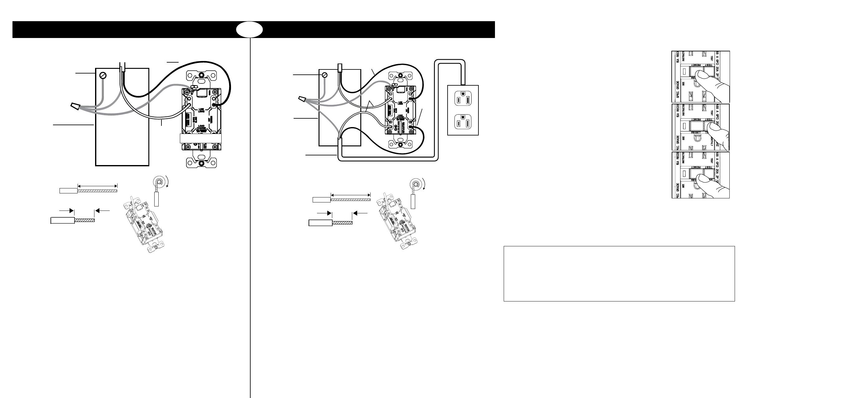
7. Connect the wires (choose A or B) ... only after reading other side completely
8. Test your work
Why perform this test?
If you miswire the GFCI, it may not prevent personal injury or death due to a ground fault
(electric shock).
Upon initial installation, if you mistakenly connect the LINE wires
to the LOAD terminals, this Eaton GFCI will not be able to be reset,
and will therefore not provide power to it’s receptacle face or load
terminals.
Procedure:
(a) Turn the power ON at the service panel. Press the RESET
button fully. Plug a lamp or radio into the GFCI (and leave it
plugged-in) to verify that the power is ON. If there is no power, go
to Troubleshooting.
(b) Press the TEST button in order to trip the device. This should
stop the flow of electricity, making the radio or lamp shut OFF
and the yellow Correct Wiring/Trip Indicator come on. To restore
power, press the RESET button.
(c) If you installed your GFCI using step 7B, now plug a lamp or
radio into surrounding receptacles to see which one(s), in
addition to the GFCI, lost power when you press the TEST
button. Do not plug life saving devices into any receptacles that
lost power. Place a “GFCI Protected” sticker on every receptacle
that lost power.
(d) Press the TEST button (then RESET button) every month to
assure proper operation.
(e) Note that this Eaton GFCI is shipped in the Tripped state and
cannot be Reset until it is wired correctly and powered from it’s
Line terminals.
(f) Note that the RESET button will pop-out. If the power goes OFF and the correct wiring/trip
indicator stays on, you have installed the GFCI receptacle correctly.
(g) LINE/LOAD reversal will be indicated by the reset button not staying in after being pressed.
Such LINE/LOAD reversal will also be indicated by failure of the Correct Wiring/Trip Indicator
to be on while the GFCI is tripped.
NOTE: If this EATON GFCI has tripped and no longer can be reset, it has reached its “End of
Life” and will no longer provide power. Replace with the same model EATON GFCI to
continue to provide ground fault protection.
A: One cable (2 or 3 wires) entering the box B: Two cables (4 or 6 wires) entering the box
OR
LINE cable brings power to the GFCI LINE cable brings power to the GFCI
Grounding connection to
box (if box has a
grounding terminal)
Grounding
connection to
box (if box has
a grounding
terminal)
Wire Connector
Wire Connector
Electrical box
Electrical
box
About wire connections:
Sidewire:
Backwire:
Backwire:
• Insert bare end fully
• Tighten screw firmly
Clockwise, 2/3 of the
way around screw
Clockwise, 2/3 of the
way around screw
Yellow
sticker
remains
in place
to cover
the
LOAD
terminals
Insert bare end fully
Tighten screw firmly
Backwire
Insert bare end fully
Tighten screw firmly
Backwire
Insert bare end fully
Tighten screw firmly
Backwire
Insert bare end fully
Tighten screw firmly
Backwire
Insert bare end fully
Tighten screw firmly
Backwire
Insert bare end fully
Tighten screw firmly
Backwire
Connect the LINE cable wires to the LINE terminals:
• The white wire connects to the White terminal (Silver)
• The black wire connects to the Hot terminal (Brass)
Connect the grounding wire (only if there is a grounding wire):
• For a box with no grounding terminal (diagram not shown): Connect the LINE
cable’s bare copper (or green) wire directly to the grounding terminal on the
GFCI receptacle
• For a box with a grounding terminal (diagram shown above): Connect a 6-inch
bare copper (or green) 12 or 14 AWG wire to the grounding terminal on the
GFCI. Also connect a similar wire to the grounding terminal on the box.
Connect the ends of these wires to the LINE cable’s bare copper (or green) wire
using a wire connector. If these wires are already in place, check the
connections.
Complete the installation:
• Fold the wires into the box, keeping the grounding wire away from the White
and Hot terminals. Screw the receptacle to the box and attach the faceplate.
• Go to step 8.
Connect the LINE cable wires to the LINE terminals:
• The white wire connects to the White terminal (Silver)
• The black wire connects to the Hot terminal (Brass)
Connect the LOAD cable wires to the LOAD terminals:
• Remove the yellow sticker to reveal the LOAD terminals
• The white wire connects to the White terminal (Silver)
• The black wire connects to the Hot terminal (Brass)
Connect the grounding wires (only if there is a grounding wire):
• Connect a 6-inch bare copper (or green) 12 or 14 AWG wire to the grounding
terminal on the GFCI. If the box has a grounding terminal, also connect a
similar wire to the grounding terminal on the box. Connect the ends of these
wires to the LINE and LOAD cable’s bare copper (or green) wire using a
wire connector. If these wires are already in place, check the connections.
Complete the installation:
• Fold the wires into the box, keeping the grounding wire away from the White
and Hot terminals. Screw the receptacle to the box and attach the faceplate.
• Go to step 8.
LOAD cable feeds
power to other
receptacle(s)
TROUBLESHOOTING
Turn the power OFF and check the wire connections against the appropriate wiring
diagram in step 7A or 7B. Make sure that there are no loose wires or loose connections.
Also, it is possible that you reversed the LINE and LOAD connections. Reverse the LINE
and LOAD connections if necessary. Start the test from the beginning of step 8 if you
rewired any connections to the GFCI.
General Information
GFCI ratings:
15A-125V AC Duplex Receptacle
20A-125V AC Duplex Receptacle
20A-125V AC Blank Face
All rated 20A feed-through
125V Class A
Wire
Wire
About wire connections:
Sidewire:
HOT
WHITE
EATON’S LIMITED 2 YEAR WARRANTY
EATON warrants its Ground Fault Circuit Interrupter
(GFCI) to be free of defects in materials and
workmanship in normal use and service for a period
of two years from date of original purchase. THIS
TWO (2) YEAR LIMITED WARRANTY IS IN LIEU
OF ALL OTHER WARRANTIES, OBLIGATIONS, OR
LIABILITIES, EXPRESSED OR IMPLIED (INCLUDING
ANY IMPLIED WARRANTY OF MERCHANTABILITY
OR FITNESS FOR A PARTICULAR PURPOSE THAT IS
IN DURATION IN EXCESS OF TWO YEARS FROM THE
DATE OF ORIGINAL CONSUMER PURCHASE). NO
AGENT, REPRESENTATIVE, OR EMPLOYEE OF EATON
HAS AUTHORITY TO INCREASE OR ALTER THE
OBLIGATIONS OF EATON UNDER THIS WARRANTY.
To obtain warranty service for any properly installed
EATON GFCI that proves defective in normal use send
the defective GFCI prepaid and insured to Quality
Control Dept. EATON, 203 Cooper Circle, Peachtree
City, GA 30269.
EATON will repair or replace the defective unit, at
its option. EATON will not be responsible under this
warranty if examination shows that the defective
condition of the unit was caused by misuse, abuse,
improper installation, alteration, improper
maintenance or repair of damage in shipment to
EATON.
EATON SHALL HAVE NO RESPONSIBILITY
FOR INSTALLATION OF THE GFCI, OR FOR ANY
PERSONAL INJURY, PROPERTY DAMAGE, OR
ANY SPECIAL, INCIDENTAL, CONTINGENT, OR
CONSEQUENTIAL DAMAGES OF ANY KIND,
RESULTING FROM DEFECTS IN THE GFCI OR THE
FAILURE OF THE PRODUCT TO FUNCTION IN THE
EVENT OF A GROUND FAULT ON ITS PROTECTED
CIRCUIT, OR FOR BREACH OF ANY EXPRESS OR
IMPLIED WARRANTY ON THIS PRODUCT.
THE EXCLUSIVE REMEDY FOR BREACH OF THE
LIMITED WARRANTY CONTAINED HEREIN IS THE
REPAIR OR REPLACEMENT OF THE DEFECTIVE
PRODUCT AT EATON’S OPTION. IMPLIED
WARRANTIES (IF ANY) INCLUDING, BUT NOT
LIMITED TO IMPLIED WARRANTIES OF FITNESS FOR
A PARTICULAR PURPOSE AND MERCHANTABILITY,
ARE LIMITED IN DURATION TO A PERIOD ENDING
TWO YEARS FROM THE DATE OF ORIGINAL
CONSUMER PURCHASE. IN NO CASE SHALL EATON
LIABILITY UNDER ANY OTHER REMEDY PRESCRIBED
BY LAW EXCEED THE PURCHASE PRICE. Some states
do not allow the exclusion or limitation of incidental
or consequential damages or allow disclaimers or
modifications of or limitations on how long an implied
warranty lasts, so the above limitations may not apply
to you. This warranty gives you specific legal rights
and you may also have other rights which vary from
state to state.
Read enclosed instructions carefully.
• Insert bare end fully
• Tighten screw firmly
7/8 inch (2.22 cm)
11/16”
(1.75 cm)
7/8 inch (2.22 cm)
11/16”
(1.75 cm)
WHITE
HOT
HOT

