Omega RHCM-40 Series Owner's manual
- Category
- Measuring, testing & control
- Type
- Owner's manual

e-mail: [email protected]
For latest product manuals:
omegamanual.info
RHCM-40 SERIES
Dew Point Transmitter with a
Humidity Option Configuration
MADE IN
Shop online at
omega.com
®
User’s Guide

Servicing North America:
U.S.A.: Omega Engineering, Inc., One Omega Drive, P.O. Box 4047
ISO 9001 Certified Stamford, CT 06907-0047 USA
Toll Free: 1-800-826-6342 TEL: (203) 359-1660
FAX: (203) 359-7700 e-mail: [email protected]
Canada: 976 Bergar
Laval (Quebec), H7L 5A1, Canada
Toll-Free: 1-800-826-6342 TEL: (514) 856-6928
FAX: (514) 856-6886 e-mail: [email protected]
For immediate technical or application assistance:
U.S.A. and Canada: Sales Service: 1-800-826-6342/1-800-TC-OMEGA
®
Customer Service: 1-800-622-2378/1-800-622-BEST
®
Engineering Service: 1-800-872-9436/1-800-USA-WHEN
®
Mexico/ TEL: 001 (203) 359-1660 FAX: 001 (203) 359-7700
Latin America: e-mail: [email protected]
Servicing Asia:
China:: 1698 Yi Shan Road, Unit 102
Min Hang District
Shanghai, China 201103 P.R.C.
Hotline: 800 819 0559/400 619 0559
e-mail: [email protected]
Servicing Europe:
Benelux: Toll-Free: 0800 099 3344 TEL: +31 20 347 21 21
FAX: +31 20 643 46 43 e-mail: [email protected]
Czech Republic: Frystatska 184
733 01 Karviná, Czech Republic
TEL: +420-59-6311899 FAX: +420-59-6311114
e-mail: [email protected]
France: Toll-Free: 0805 541 038 TEL: 01 57 32 48 17
FAX: 01 57 32 48 18 e-mail: [email protected]
Germany/ Austria: Daimlerstrasse 26
D-75392 Deckenpfronn, Germany
Toll-Free: 0800 8266342 TEL: +49 (0) 7056 9398-0
FAX: +49 (0) 7056 9398-29 e-mail: [email protected]
United Kingdom: OMEGA Engineering Ltd.
ISO 9001 Certified One Omega Drive, River Bend Technology Centre, Northbank
Irlam, Manchester M44 5BD United Kingdom
Toll-Free: 0800-488-488 TEL: +44 (0) 161 777-6611
FAX: +44 (0) 161 777-6622 e-mail: [email protected]
OMEGAnet
®
Online Service Internet e-mail
omega.com info@omega.com
It is the policy of OMEGA Engineering, Inc. to comply with all worldwide safety and EMC/EMI
regulations that apply. OMEGA is constantly pursuing certification of its products to the European New
Approach Directives. OMEGA will add the CE mark to every appropriate device upon certification.
The information contained in this document is believed to be correct, but OMEGA accepts no liability for any
errors it contains, and reserves the right to alter specifications without notice.
WARNING: These products are not designed for use in, and should not be used for, human applications.

1
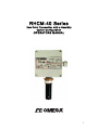
RHCM-40 Series
Dew Point Transmitter with a Humidity
Option Configuration
OPERATORS MANUAL

2
RHCM-40
QUICK STARTUP GUIDE
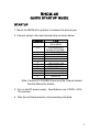
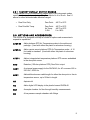
STARTUP
1. Mount the RHCM-40 in position to measure the desired gas.
2. Connect wiring to the main terminal strip as shown below:
TERMINAL
ITEM
1,2
SERVOLOCK SIGNAL
OR ALARM 2
3,4
CLEAN MIRROR
SIGNAL OR ALARM 1
5
CHASSIS GROUND
6
ANALOG OUTPUT 2
7
ANALOG OUTPUT 1
8
ANALOG OUTPUT RET.
9
FOR FACTORY USE
10
FOR FACTORY USE
11
RS232 RETURN
12
DC POWER IN (+)
13
DC POWER IN (-)
14
RS232 TX
15
RS232 RX
Note: Connect DC POWER IN and only the Outputs desired.
See the Manual for details.
3. Turn on the DC power supply. Specifications are: 24VDC ± 20%,
1A maximum.
4. After the self-test procedure, start recording valid data.

3
TABLE OF CONTENTS Page
1.0 Quick Startup Guide 2
2.0 Introduction 6
2.1 General Description 6
2.2 Standard Factory Configurations 7
2.2.1 Factory Default Output Ranges 9
2.3 Options and Accessories 9
3.0 Installation 10
3.1 Placement of Instrument 10
3.2 Mounting 10
3.2.1 Wall Mount 10
3.2.2 Duct Mount 10
3.2.3 Remote Mount 10
3.2.4 Pipe Mount 11
3.3 Electrical Wiring 11
3.3.1 Power Supply 11
3.3.2 Input/Output Wiring 13
3.4 Selection of Analog Outputs 14
4.0 Operation 15
4.1 Placement of Instrument 15
4.2 Flow Control 15
4.3 Clean Mirror Signal 15
4.4 Using the RS-232 Serial Port 16
4.4.1 Serial Port Setup 16
4.4.2 Programming via the Serial Port 17
4.4.3 Changing the Digital Display 17
4.4.4 Relay Outputs 19
4.4.4.1 Configuring Relays as Alarms 20
4.4.5 Calibrating the Analog Outputs 21
4.4.6 Programming the Serial Output 22
4.4.7 Auto Validation Cycle 23
5.0 Maintenance 24
5.1 Routine Maintenance 24
5.1.1 Mirror Cleaning Schedule 24
5.1.2 Cleaning the Mirror 24

4
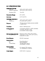
6.0 Specifications 26
7.0 Appendix 27
7.1 NIST Traceability 28
7.2 Mounting Dimensions 29
7.2.1 Wall Mount (plastic housing) 29
7.2.2 Duct Mount (metal housing) 30

5
LIST OF ILLUSTRATIONS Page
2-1 Standard Configurations 6
3-1 Terminal Strip Wiring 13
3-2 Output Selector Switches 14
5-1 Cleaning the Mirror 25
LIST OF TABLES
3-1 Terminal Strip Wiring 12
3-2 Analog Output Switch Settings 14
4-1 Serial Cable Wiring 16

6
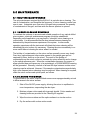
2.0 INTRODUCTION
2.1 GENERAL DESCRIPTION
The RHCM-40 Dew Point/Humidity Transmitter is an optical chilled mirror
hygrometer, designed to continuously measure the moisture content in gases.
With an option to acquire an air temperature probe, this transmitter can than
display dew point, humidity and temperature and have a signal out for two of the
following three parameters, dew point, humidity or temperature The instrument is
powered by 24VDC. It uses the chilled mirror dew point temperature
condensation principle to determine the water vapor concentration in gas
mixtures, and a platinum resistance thermometer to accurately measure that
temperature. This principle is fully explained in the Appendix to this manual.
Outputs include 4 to 20 mA (Factory default unless specified otherwise when
ordering), 0 to 5VDC, or 0 to 10VDC, field-selectable. Two sets of analog
outputs are supplied, unless Dew Point only is ordered. Additional outputs
include an RS-232C serial port, as well as electrically isolated relay contacts.
Various housings are available for the RHCM-40. These include a plastic (IP65)
dust-tight and water resistant package, as well as an aluminum housing with
conduit fittings. Many options and accessories are available, and these are
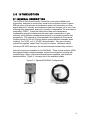
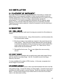
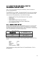
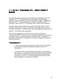
described below. Figure 2-1 shows a few of the available models.
Figure 2-1 Standard RHCM-40 Configurations
Wall Mount Remote Mount

7
Duct Mount Pipe Mount
2.2 STANDARD FACTORY CONFIGURATIONS
The RHCM-40 is designed with a large number of standard configurations for
user convenience, as shown here. In addition, you can consult the Factory for
special configurations if needed.
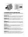
RHCM-40-PL-W A wall-mount configured Dew Point/Humidity transmitter***
with a plastic enclosure, a two-stage chilled mirror sensor, two programmable
analog outputs, an RS-232 bi-directional serial port, and alarm relays.
RHCM-40-AL-W A wall-mount configured Dew Point/Humidity transmitter***
with an aluminum enclosure, a two-stage chilled mirror sensor, two
programmable analog outputs, an RS-232 bi-directional serial port, and alarm
relays.
RHCM-40-PL-D A duct-mount configured Dew Point/Humidity transmitter***
with a plastic enclosure, a two-stage chilled mirror sensor, two programmable
analog outputs, an RS-232 bi-directional serial port, duct mount flange kit, and
alarm relays.
RHCM-40-AL-D A duct-mount configured Dew Point/Humidity transmitter***
with an aluminum enclosure, a two-stage chilled mirror sensor, two
programmable analog outputs, an RS-232 bi-directional serial port, duct mount
flange kit, and alarm relays.
RHCM-40-PL-R A remote-mount configured Dew Point/Humidity
transmitter*** with a plastic enclosure, a two-stage chilled mirror sensor, two
programmable analog outputs, an RS-232 bi-directional serial port, duct mount
flange kit, 6 foot cable between sensor and electronics, and alarm relays.
RHCM-40-AL-R A remote-mount configured Dew Point/Humidity
transmitter*** with an aluminum enclosure, a two-stage chilled mirror sensor, two
programmable analog outputs, an RS-232 bi-directional serial port, duct mount
flange kit, 6 foot cable between sensor and electronics, and alarm relays.

8
RHCM-40-PL-P A pipe-mount configured Dew Point/Humidity transmitter***
with an plastic enclosure, a two-stage chilled mirror sensor, two programmable
analog outputs, an RS-232 bi-directional serial port, 1-1/4 inch NPT brass pipe
mount fitting, and alarm relays.
RHCM-40-AL-P A pipe-mount configured Dew Point/Humidity transmitter***
with an aluminum enclosure, a two-stage chilled mirror sensor, two
programmable analog outputs, an RS-232 bi-directional serial port, 1-1/4 inch
NPT brass pipe mount fitting, and alarm relays.
**** this transmitter is typically a dew point transmitter and can only be
configured as a humidity transmitter when the air temperature probe option is
purchased

9
2.2.1 FACTORY DEFAULT OUTPUT RANGES
These standard output measurement ranges apply to all instruments unless
specified otherwise when ordering. They correspond to 4 to 20 mA. See 2.1
above for other field-selectable electrical ranges.
• Dew Point Only Dew Point: -40°C to 60°C
• Dew Point/Air Temp. Dew Point: -40°C to 60°C
Air Temp: -40°C to 60°C
% RH 0 to 100%
2.3 OPTIONS AND ACCESSORIES
The RHCM-40 is designed to accept a number of options and accessories to
expand its capabilities.
ATDT-W Add a platinum RTD Air Temperature probe to the wall-mount
package. (Used with either the plastic or aluminum housing.)
ATDT-R Add a remote-mount platinum RTD Air Temperature probe. A 10
foot cable is standard. (Used with either the plastic or aluminum
housing.)
ATDT-I Add an integrated air temperature platinum RTD sensor embedded
in the dew point sensor.
RTD Resistive (100 ohm platinum RTD) Dew Point output
ACDT A universal power supply for the RHCM-40, for AC sources of 85 to
230 VAC, 50/60 Hz.
ECDT Add additional sensor cable length for either the dew point or the air
temperature sensor, up to 50 feet in length.
AR Aspirator kit
RD Add a digital LCD display to the plastic-housed RHCM-40.
SC1 A sample chamber for flow-through humidity measurements
SC A low pressure sample chamber with fittings

10
3.0 INSTALLATION
3.1 PLACEMENT OF INSTRUMENT
If possible, locate the RHCM-40 dewpoint/humidity Transmitter in a clean area
where the air to be measured is allowed to freely move around the enclosure.
Optimal performance of the instrument is experienced when air is gently moving
over the chilled mirror sensor, providing a representative sample for
measurement. If you have purchased an instrument with the optional digital
display, choose a location where the display may be conveniently observed.
Depending on the location selected, it may be convenient to wire the instrument
prior to mounting.
3.2 MOUNTING
3.2.1 WALL MOUNT
Instruments with the plastic wall mount housing are mounted to a flat surface as
follows:
1. Remove the front cover. Using a flat screwdriver, carefully unscrew the
four slotted plastic screws.
2. Mounting screws (not provided) are inserted in the same holes as the
cover screws. They must have a head diameter that is small enough
to fit inside the clearance holes, but large enough to press against the
collar located at the bottom of the holes. No. 8 pan head or round
head screws are recommended.
3. Reinstall the front cover. Do not over-tighten the cover mounting
screws.
3.2.2 DUCT MOUNT
The duct mount unit is available with a metal housing and metal conduit fittings,
and has a built-in mounting flange. Use No. 6 screws to mount the flange
securely to the duct.
It is also available with a plastic (IP65) housing. In this case, a separate duct
mount flange kit is provided.
3.2.3 REMOTE MOUNT
A 6 foot (1.8 meter) remote sensor cable is provided between the sensor and the
instrument housing. Consult the factory for other lengths. A remote mount unit is
available with either a plastic or metal housing. Mount the housing as described
above. If a duct mount flange kit is provided, mount it to the duct in a location
close to the electronics housing.

11
3.2.4 PIPE MOUNT
The pipe mount configurations are available with either a plastic or metal
electronics housing. They include a 1-¼ inch NPT brass pipe mount fitting. A
corresponding female mating fitting, user-supplied, should be mounted in a gas-
tight manner to a flat surface of a duct, pipe, or chamber wall containing the gas
to be measured. Clean all surfaces of the pipe mount of oil, grease, and
contaminants.
To install the mount and sensor:
Screw the front portion of the mounting sleeve (the tapered NPT fitting)
into the pre-mounted user-supplied mating fitting. Teflon™ tape or pipe
thread sealant may be used for a good seal. Do not over-tighten.
If the Type SC1 sample chamber is to be used, simply screw it down to any flat
surface, and connect ¼ inch OD tubing to the inlet and outlet compression
fittings. Tubing should be reasonably non-hygroscopic, such as copper,
Teflon™, or Tygon™. Do not use PVC tubing. See the above instructions for
probe mounting.
3.3 ELECTRICAL WIRING
3.3.1 POWER SUPPLY
You will need a power supply voltage of 24VDV +/- 20% at 1A for each DewTrak
ll that you are installing. Stranded wire, 18 gauge minimum, color coded, should
be used. Route the wires through the feed-through bushing on the body of the
unit, and connect them to Terminal Strip TB1 as shown in Table 3-1 and Figure
3-1 below.

12
CAUTION: BE SURE TO OBSERVE CORRECT WIRING POLARITY.
DO NOT APPLY POWER TO THE UNIT UNTIL THE
INSTALLATION HAS BEEN COMPLETED.
Table 3-1 Terminal Strip Wiring
TERMINAL
ITEM
1,2
SERVOLOCK SIGNAL
OR ALARM 2
3,4
CLEAN MIRROR
SIGNAL OR ALARM 1
5
CHASSIS GROUND
6
ANALOG OUTPUT 2
7
ANALOG OUTPUT 1
8
ANALOG OUTPUT RET.
9
FOR FACTORY USE
10
FOR FACTORY USE
11
RS232 RETURN
12
DC POWER IN (+)
13
DC POWER IN (-)
14
RS232 TX
15
RS232 RX

13
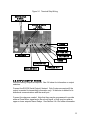
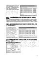
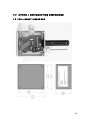
Figure 3-1 Terminal Strip Wiring
3.3.2 INPUT/OUTPUT WIRING
Wire the Analog Outputs as required. See 3.4 below for information on output
selection.
Connect the RS-232 Serial Output if desired. Only 2 wires are required if the
output is needed for transmitting information only. A third wire is added for bi-
directional communications with the serial port.
Connect the relays as needed. Note that they may be programmed to provide
either a Clean Mirror signal and a ServoLock signal, or they may be used as
upper or lower setpoint Alarm Relays. See Section 4.4.4 for further information.
DC PWR IN
(+)
RS232
RTN
ANALOG OUT
RTN
ANALOG OUT
1
ANALOG OUT
2
RS232
RX
RS232
TX
DC PWR IN (-
)
CLEAN MIRROR
SIGNAL
OR ALARM 1
SERVOLOCK
SIGNAL
OR ALARM 2
CHASSIS
GND

14
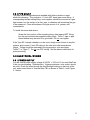
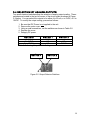
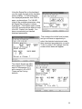
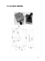
3.4 SELECTION OF ANALOG OUTPUTS
Two small electrical switches allow the selection of analog output scaling. These
switches are located in the top left corner of the circuit board as shown in Figure
3-2 below. You can select the outputs to be either 4 to 20 mA, o to 5VDC, or 0 to
10VDC. To modify the output scaling, proceed as follows:
1. Be sure that DC Power is not applied to the unit.
2. Remove the outer cover.
3. Using a small screwdriver, set the switches as shown in Table 3-2.
4. Replace the cover.
5. Reapply DC power.
OUTPUTS
SWITCH 1
SWITCH 2
4 to 20 mA
DOWN
----
0 to 5VDC
UP
UP
0 to 10VDC
UP
DOWN
Table 3-2. Analog Output Switch Settings
Figure 3-2 Output Selector Switches
SWITCH 1
SWITCH 2

15
4.0 OPERATION
4.1 PLACEMENT OF INSTRUMENT
If possible, locate the RHCM-40 Humidity Transmitter in a clean area where the air to
be measured is allowed to freely move around the enclosure. Optimal performance
of the instrument is experienced when air is gently moving over the chilled mirror
sensor, providing a representative sample for measurement.
4.2 FLOW CONTROL
The sensor probe is designed so that the flow rate can be changed. This is achieved
by means of rotating the sensor cover around the sensor probe base. By aligning
and misaligning the holes on the sensor cover with those of the sensor base, the air
flow can be controlled across the surface of the chilled mirror sensor. The proper
alignment of the holes (and thus gas flow control) depends on the application. The
RHCM-40 sensor is designed to accommodate various application conditions.
Optimal performance of the sensor may require several trial and error adjustments.
“Optimal” performance is defined by the response time of the sensor, (lower flow
results in a slower response). Accuracy is unaffected by the flow.
Flow control can also be achieved by constructing a simple external sampling system.
You can use an Omega Engineering Sample Chamber, Model SC1, along with a
flowmeter which can adjust the flow between 0 to 5 SCFH. Contact the factory for
more details.
4.3 CLEAN MIRROR SIGNAL
The RHCM-40 Humidity Transmitter features an electro-optical technique to detect
and maintain the dew layer on the mirror surface. By use of the Auto Validation
Cycle, the system will indicate when the mirror needs attention. In the factory default
configuration, the Clean Mirror alarm relay actuates when the mirror requires periodic
cleaning. An indication also appears on the RS-232 serial output. When the Clean
Mirror alarm actuates, the instrument is still operational and the accuracy of the
measurement is not affected by the presence of contaminants on the mirror surface.
Note: This alarm requires that the mirror be cleaned within a reasonable period of
time, or the specified accuracy can no longer be guaranteed.
There are many variables determining the frequency that your transmitters require
maintenance. These include flow rate and the amount of particulate matter in the gas
being measured. Once you determine the typical contamination rate in your unique
application, it is recommended that you initiate a periodic maintenance schedule.
This minimizes the chance of obtaining incorrect data due to mirror contamination.

16
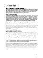
4.4 USING THE RS-232C SERIAL PORT TO
REPROGRAM YOUR SETTINGS
Note: If the Factory Default settings are satisfactory, there is no reason to
perform any programming.
The RHCM-40 is very versatile. Through the Serial Port, the user has complete
control over the display units, the electrical outputs, and other features as well.
Here are some of the parameters you can select and change:
• Displayed Values (if the optional display has been supplied)
• Output Units
• Output Ranges
• Alarm Scaling (if alarms have been selected)
• RS-232 Settings (Elapsed Time Stamp, Update Rate)
• Auto Validation (On or Off)
4.4.1 SERIAL PORT SETUP
You will need a serial cable with a standard DB-9 connector on one end, which
will plug into the standard serial port connector on the back of your computer.
The other end will have three stripped wires, which will connect to Terminal Strip
TB1 on the RHCM-40 circuit board as shown below:
Table 4-1 Serial Cable Wiring
DB-9 SERIAL
CONNECTOR
TB1 TERMINAL STRIP
Pin 2
TX – Term. 14
Pin 3
RX – Term 15
Pin 5
RTN – Term. 11
Using a terminal emulation program, such as HyperTerminal, set your PC Com
Port to:
BAUD: 19200
BITS 8
STOP BITS 1
PARITY NONE
FLOW CONTROL NONE
HyperTerminal has a setting called Control for Terminal Emulation. Set it to
AUTODETECT.

17
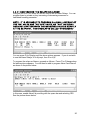
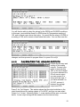
After connecting both ends of the
serial cable, apply power to the
RHCM-40. A window should be
seen, which will show some
warm-up and self test data. After
the self checking and warm-up
period, the window will display
information similar to the photo
shown here. This is the default
condition.
4.4.2 PROGRAMMING THE RHCM-40 VIA THE SERIAL
PORT
If you do not see a window similar to the one shown above, you will not be able
to program this instrument. Check your terminal emulation program, the power
supply, and check the interconnecting cable wiring as shown in Table 5 -1 above.
NOTE: WHEN PROGRAMMING ALPHABETIC CHARACTERS, USE
UPPER CASE ONLY.
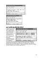
To begin reprogramming,
press the ESCape key on
your computer keyboard. The
window will change to that
shown here. To select the
desired parameter, simply
select the first letter as
shown. You will find it quite
intuitive once you try it.
Several programming
examples will be shown here.
4.4.3 CHANGING THE DIGITAL DISPLAY (if you have the
Display option)
Press the D key to change the displayed
values. The window at the left will
appear. Press the A key to keep the
present values, or the C key to change
them. In this case, you will change them.
So, you will press C to change the values.

18
Using the Space Bar on the keyboard,
you can toggle through all the available
units to display. You will change the
first displayed parameter from %RH to
ppmv, as shown here. For VALUE1,
cycle all the available parameters using
the Space Bar until ppmv is shown.
Press Enter. Press Enter again to keep
VALUE2, and press Enter again to keep
VALUE3. Press A for A)ccept. You
have now selected your desired
displayed parameters.
The screen at the left will now be seen,
and you will have an opportunity to
select the electrical outputs and make
them represent any parameter you wish.
To do so, press C for C)hange, and the
screen shown below will appear.
The outputs shown are %RH
with a range of 0 to 100%RH,
and Air Temperature (AT)
with a range of -40 to 60°C.
These are the Factory
defaults.
Page is loading ...
Page is loading ...
Page is loading ...
Page is loading ...
Page is loading ...
Page is loading ...
Page is loading ...
Page is loading ...
Page is loading ...
Page is loading ...
Page is loading ...
Page is loading ...
Page is loading ...
Page is loading ...
Page is loading ...
Page is loading ...
-
 1
1
-
 2
2
-
 3
3
-
 4
4
-
 5
5
-
 6
6
-
 7
7
-
 8
8
-
 9
9
-
 10
10
-
 11
11
-
 12
12
-
 13
13
-
 14
14
-
 15
15
-
 16
16
-
 17
17
-
 18
18
-
 19
19
-
 20
20
-
 21
21
-
 22
22
-
 23
23
-
 24
24
-
 25
25
-
 26
26
-
 27
27
-
 28
28
-
 29
29
-
 30
30
-
 31
31
-
 32
32
-
 33
33
-
 34
34
-
 35
35
-
 36
36


Omega RHCM-40 Series Owner's manual
- Category
- Measuring, testing & control
- Type
- Owner's manual
Ask a question and I''ll find the answer in the document
Finding information in a document is now easier with AI
Related papers
-
Omega DPG-110 Owner's manual
-
-
Omega DPG110 User manual
-
-
-
-
-
-
-
Other documents
-
Minka Group 1430-84 User manual
-
Omega Engineering M1982/0902 User manual
-
Watts Oil Content Monitor Owner's manual
-
Hitachi Dynamic Link Manager User manual
-
-
-
Michell Instruments MDM300 I.S User manual
-
Dwyer Series RHP-W User manual
-
 JENCO 701 Operating instructions
-
Omega Speaker Systems HX93DA User manual
