Page is loading ...

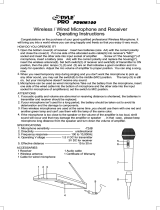
1200 Series Professional
VHF Wireless Systems
ATW-1235
UniPak
™
Transmitter System
ATW-1236
Handheld Dynamic Microphone System
ATW-1237
Handheld Condenser Microphone System
Installation and Operation

2
Receiver Installation
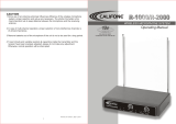
Location
For best operation the receiver should be at least 3 ft. above
the ground and at least 3 ft. away from a wall or metal surface
to minimize reflections. The
transmitter should be at
least 3 ft. from the receiver,
as shown in Figure A.
Keep antennas away from
noise sources such as digital
equipment, motors,
automobiles and neon
lights, as well as large
metal objects.
Output Connections
There are two audio outputs on the back of the receiver:
balanced (31.6 mV) and unbalanced (100 mV) . Use shielded
audio cable for the connection between the receiver and the
mixer. If the input of the mixer is a
1
⁄
4
" jack, connect a cable
from the
1
⁄
4
" unbalanced audio output on the back of the
receiver to the mixer. If the input of the mixer is an XLR-type
input, connect a cable from the balanced XLR-type audio
output on the back of the receiver to the mixer.
The two isolated audio outputs permit simultaneous feeds
to both unbalanced and balanced inputs. For example, both
a guitar amp and a mixer can be driven by the receiver.
Antennas
Assemble the two whip antennas
to the special connectors provided.
Screw the whips into the threaded
side holes at the rear of the
connector (Fig. B).
Install the included yellow vinyl
caps over the antenna tips to
increase their visibility when the
antenna location may permit
contact with people or animals.
(Cont. on pg. 4)
ANT. A
Fig. B
Antenna Assembly
Fig. A
Professional VHF Wireless Systems
Installation and Operation
CAUTION! The circuits inside the receiver and transmitter have
been precisely adjusted for optimum performance and
compliance with federal regulations. Do not attempt to open the
receiver or transmitter. To do so will void the warranty, and may
cause improper operation.
Individuals with implanted cardiac pacemakers or AICD
devices: Please see notice on back cover.
This device complies with part 15 of the FCC Rules. Operation is
subject to the condition that this device does not cause harmful
interference.
This device complies with INDUSTRY CANADA R.S.S. 210, en
conformité avec IC: RSS-210/CNR210. Operation is subject to
the following conditions: 1) This device may not cause harmful
interference and 2) this device must accept any interference
received, including interference which may cause undesired
operation.
Introduction
Thank you for choosing an Audio-Technica professional
wireless system. You have joined thousands of other satisfied
customers who have chosen our products because of their
quality, performance and reliability. This Audio-Technica
wireless microphone system is the successful result of years
of design and manufacturing experience.
Each professional wireless system includes a receiver and
either a body-pack or handheld transmitter on specific crystal-
controlled frequency.
The receiver features true diversity reception. Two antennas
feed two completely independent RF sections on the same
frequency; automatic logic circuitry continuously compares
and selects the superior received signal, providing better
sound quality and reducing the possibility of interference and
dropouts. The receiver is half-width for a standard 19" (1U)
rack mount. Two receivers (on different frequencies) can be
mounted side by side, using an AT8628 joining plate kit.
The versatile UniPak
™
body-pack transmitter has both low- and
high-impedance inputs plus a bias connection, for use with
dynamic and electret condenser microphones, as well as Hi-Z
instrument pickups. The UniPak and handheld transmitters use
internal 9-volt batteries and have Off/Standby/On switches and
battery condition indicators.
Please note that in multiple-system applications there must
be a transmitter-receiver combination on a
separate
frequency for each input desired (only one transmitter for each
receiver). Because the wireless frequencies are in or near VHF
TV frequencies, only certain wireless frequencies are useable
in a particular geographic area. Also, only certain of the avail-
able operating frequencies may be used together. (Frequency
selection information will be found on page 7.)
To prevent electric shock, do not remove the
cover. There are no user-serviceable parts
inside. Internal adjustments are for qualified
professionals only. Refer all servicing to
qualified service personnel.
Pour prévenir un choc électrique, ne pas ouvrir
le couvercle. Il n’y aucune pièces de rechanges
à l’intérieur. Tout ajustement interne doit être
fait par une personne qualifié seulement.
Référez tout réparation au personnel qualifié.
AVIS
RISQUE DE CHOC ÉLECTRIQUE
NE PAS OUVRIR
CAUTION
RISK OF ELECTRIC SHOCK
DO NOT OPEN
Warning: To prevent fire or shock hazard, do
not expose this appliance to rain or moisture.
Attention: Pour prévenir feu ou choc
électrique, ne pas exposé l’appareil à la pluie
ou à l’humidité.

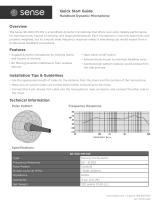
Rear Panel Controls and Functions (Fig. D)
7 TUNER “B” ANTENNA JACK: Antenna connector for
tuner “B.” Attach the antenna directly, or extend it
with an antenna cable.
8 SQUELCH CONTROL: Adjusts level of noise-muting
circuit (preset at factory but can be adjusted as
circumstances warrant).
9 BALANCED AUDIO OUTPUT JACK: XLRM-type connec-
tor. A standard 2-conductor shielded cable can be used
to connect the receiver output to a balanced microphone
level input on a mixer.
10 GROUND LIFT SWITCH: Disconnects the ground pin of
the balanced output (9) from ground. Normally, the
switch should be to the left (ground connected). If hum
caused by a ground loop occurs, slide switch to the right.
11 UNBALANCED AUDIO OUTPUT JACK:
1
⁄
4
" phone jack.
Can be connected to an unbalanced aux-level input of a
mixer or tape recorder.
12 DC POWER INPUT: For an external 12-18V DC source
(requires 350 mA).
13 AC POWER: Power cord for 120V AC power input.
14 TUNER “A” ANTENNA JACK: Antenna connector for
tuner “A.” Attach the antenna directly, or extend it
with an antenna cable.
3
Front Panel Controls and Functions (Fig. C)
1 POWER SWITCH/INDICATOR: Press switch on, and
the “power” indicator will light.
2 RF SIGNAL LEVEL INDICATOR: Indicates the strength
of the RF signal received from the transmitter. The
LEDs will light up from left to right.
3 AF LEVEL INDICATOR: Indicates the audio modulation
level of the received signal. (Not affected by the
setting of the AF Level control.)
4 TUNER OPERATION INDICATOR: Indicates which
tuner has the better reception and is in operation.
5 AF LEVEL CONTROL: Adjusts the level at both audio
output jacks.
6 MOUNTING ADAPTERS: For mounting the receiver in
any standard 19" rack. Attach to receiver with screws
supplied. (Use optional AT8628 joining plate kit to
mount two receivers side-by-side.)
Receiver Controls And Functions
Fig. C Receiver Front Panel
Fig. D Receiver Rear Panel
5431 6
131211
97
14
6 2
8
10

Battery Selection and Installation
An alkaline 9-volt battery is recommended. Make certain the
transmitter power switch is Off before installing or changing
batteries.
When inserting the battery,
observe correct polarity as
marked inside the battery compartment.
The transmitter
housings are designed to prevent incorrect installation of the
battery;
do not force the battery in.
Reversed batteries may
cause damage to the transmitter.
UniPak
Transmitter Battery Installation
1. Slide off the battery cover as shown in Figure E.
2. Insert a 9V battery, observing correct polarity as marked
inside the battery compartment.
3. Replace the battery cover. Set the cover in place on the
transmitter as shown in Figure F, so it rests fully on the
case, then slide it forward firmly until it clicks closed.
(Cont. from pg. 2)
Attach the antennas to the antenna input jacks. The antennas
are normally positioned in the shape of a “V” (45° from
vertical) for best reception.
Do not try to move the antenna rod after the connector
shell has been tightened down. Always loosen the
connector shell completely before repositioning the rod.
If there is not sufficient space above the receiver and/or if the
receiver is installed in a metal cabinet, the antennas can be
mounted in the threaded holes in the back of the connectors
so the antennas will stick straight out from the back of the
receiver. Use one set of threaded holes or the other; do not
attempt to bend the antenna rods. The optional accessory
ATW-RA1 rack-mount antenna kit brings antenna inputs to the
front of the receiver. When two receivers are mounted side-
by-side in single 19" rack space, one ATW-RA1 is required for
each receiver.
Power Connections
Connect to a standard 120 volt 60 Hz AC power outlet. If
there is no AC power available, the back panel is equipped
with a jack for an external 12-18 volt DC source. The jack
takes a standard 2.5 mm I.D. coaxial DC power plug, center
negative
. Power from the DC input jack is switched by the
front-panel Power switch.
4
Handheld Transmitter Battery Installation
1. While holding the middle of the microphone body normally,
unscrew the battery cover (bottom 3" section) as shown in
Figure G.
2. Lift the white “battery keeper” arm and carefully insert a
fresh 9V alkaline battery, observing polarity markings
(Fig. H).
3. Replace the battery cover.
Do not overtighten.
Fig. G
Fig. H
Transmitter Setup
Battery Condition Indicator
After the battery is installed, turn the power on. The battery
condition indicator LED (Fig. I/J) should flash momentarily.
If it does not, the battery is installed incorrectly or it is dead.
If the indicator LED
stays
on (does not flash), the battery
voltage is low and the battery should be replaced. If this
happens during use, replace the battery immediately to
ensure continued operation.
UniPak Transmitter Input Connection
Connect an audio input device (microphone or guitar cable) to
the audio input connector on the bottom of the transmitter. A
number of Audio-Technica professional microphones and cables
are available separately, pre-terminated with a UniPak input
connector (see “Optional System Accessories” on page 6).
Fig. E
Fig. I
Fig. J
Input
Connector
Battery
Condition
Indicator
Power Switch
(Off/Standby/On)
Power Switch
(Off/Standby/On)
Battery Condition
Indicator
Fig. F

5
Turn down the AF Level of the receiver as well as the mixer.
Switch on the receiver. Do
not
switch on the transmitter yet.
Receiver On…
The power indicator will light up and one of the tuner operation
indicator LEDs (A or B) will light, even though the transmitter is
not on. If any of the RF LEDs light up at this point, there may be
RF interference in the area, or a nearby TV station is on the
same frequency. Check the frequency of the system against the
chart on page 7 to ensure you have the proper frequency for
your area. The frequency is marked on the back panel of the
receiver.
Transmitter On…
When the transmitter is switched on and in normal operation,
the receiver’s RF signal level indicators will light up from left to
right. For optimum performance at least four, and preferably five,
of the signal strength indicators should light up when the trans-
mitter is switched on. The transmitters have a three-position
power switch. When the switch is set to “Standby,” the trans-
mitter produces RF with no audio signal. When the switch is
“On,” the transmitter produces both RF and audio.
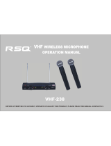
Setting Levels
Correct adjustment of transmitter audio input, receiver audio out-
put, and mixer/amplifier input and output levels is important for
optimum system performance.
• ATW-T35 UniPak Transmitter
Trimmer adjustments in the UniPak transmitter (Fig. K) will
enable you to use microphones or instruments with different
output levels.
1. Set both the transmitter Mic Level (M) and Guitar Level (G)
controls to their full counter-clockwise position (minimum). (The
level control not being used should be set to minimum.)
2. Set the receiver’s AF Level control to “0.”
3. Plug the mic or instrument into the transmitter and power up
the system.
4.
For MIC:
Make an initial adjustment of the mixer’s level
controls that will allow audio through the system as you increase
the transmitter’s Mic Level.
For INSTRUMENT:
Make an initial adjustment of the instru-
ment amplifier input level control that will allow audio through
the system as you increase the transmitter’s Guitar Level.
5.
For MIC:
While speaking/singing into the microphone at typi-
cally-loud levels, turn up the transmitter’s Mic Level (M) control
until the maximum audio output of the mic lights about three or
four green LED segments on the receiver’s AF Level indicator.
For INSTRUMENT:
While playing the instrument at typically-
loud levels, turn up the transmitter’s Guitar Level (G) control until
the maximum audio output of the instrument lights about three
or four green LED segments on the receiver’s AF Level indicator.
NOTE:
Do not set the transmitter level too high (as indicated
by lighting of the red LED) – doing so will cause the system to
overload and distort.
6.
For MIC:
Next, while again speaking/singing into the
microphone at typically-loud levels, adjust the mixer’s input trim
control so the highest sound pressure level going into the micro-
phone causes no input overload in the mixer, and yet permits
the mixer’s channel and output level controls to operate in their
“normal” range (not set too high or too low).
NOTE:
With the receiver’s AF Level control set at “0,” the
balanced output voltage will be similar to that of a typical wired
microphone. However, the AF Level control may be adjusted
to accommodate some microphone inputs – for example, those
with limited-range or no input trim controls.
For INSTRUMENT:
Next, while again playing the instrument
at typically-loud levels, adjust the receiver’s AF Level control so
the highest signal level causes no input overload in the instru-
ment amplifier, and yet permits the amplifier’s input level
controls to operate in their “normal” range (not set too high
or too low).
NOTE:
With some instrument amplifiers, the receiver’s AF Level
control may need to be adjusted to between “0” and “+6” to
better drive the amplifier.
CAUTION! The small trimmer controls are
delicate
; use only a
small screwdriver or alignment tool with a maximum
3
/
32
"-wide
blade. Do
not
force the trimmers beyond their normal 210°
range of rotation.
• ATW-T36HE and ATW-T37C Handheld Transmitters
The 1200 Series handheld transmitters have factory pre-set
audio input levels.
1. Set the receiver’s AF Level control to “0.”
2. Turn the transmitter on and power up the system.
3. Turn down the mixer’s input trim control (if provided) on
the selected channel; make an initial adjustment of the mixer
channel and output level controls that will allow audio through
the system.
4. While speaking/singing into the microphone at typically-loud
levels, adjust the mixer’s input trim control so the highest sound
pressure level going into the microphone causes no input over-
load in the mixer, and yet permits the mixer’s level controls to
operate in their “normal” range (not set too high or too low).
NOTE:
With the receiver’s AF Level set at “0,” its balanced out-
put voltage will be similar to that of a typical wired microphone.
However, the AF Level may need to be adjusted to accommo-
date some microphone inputs.
Receiver Squelch
The squelch control on the back panel of the receiver is preset
at the factory, but can be adjusted if you must use the system
in an area with considerable RF interference. If there is
interference in the receiver's audio, adjust the squelch control so
the system will receive the signal from
your
transmitter but will
“squelch” or eliminate the unwanted background RF noise. This
adjustment can cause a reduction in useable range of the wire-
less transmitter, so set the control to the
lowest
position that
reliably mutes the unwanted RF signals.
Microphone
Trimmer (M)
Guitar
Trimmer (G)
Fig. K
5
System Operation

6
Specifications
†
Optional System Accessories
OVERALL SYSTEM
Operating Frequency VHF high band, 169.505 to 213.800 MHz
Frequency Stability ±0.005%, single-frequency
crystal-controlled
Modulation Mode FM
Maximum Deviation Range ±30 kHz, traveling frequencies ±15 kHz
Operating Range 200' minimum
Operating Temperature Range 41° F (5° C) to 113° F (45° C)
Frequency Response 100 Hz to 15 kHz
RECEIVER
Receiving System Dual independent receivers, automatic
switching diversity reception
Image Rejection ≥ 60 dB
Signal-to-noise Ratio 112 dB at 30 kHz deviation
(IEC-weighted), maximum modulation
75 kHz
Total Harmonic Distortion ≤1% (10 kHz deviation @ 1 kHz)
Sensitivity 5.6 µV for 60 dB S/N (IEC-weighted)
Intermediate Frequency 10.7 MHz
Audio Output
Unbalanced: 100 mV (at 1 kHz, ±5 kHz deviation,
10k ohm load)
Balanced: 31.6 mV (at 1 kHz, ±5 kHz deviation,
10k ohm load)
Output Connectors Unbalanced:
1
/
4
" phone jack
Balanced: XLRM-type
Power Supply 120V AC 60 Hz; or 12-18V DC,
350 mA, with external supply
Dimensions 8.27" (210.0 mm) W x 1.93" (49.0 mm) H
x 8.86" (225.0 mm) D
Weight 3.9 lbs (1.8 kgs)
Accessories Included Two whip antennas, rack mount adapters
UNIPAK
TRANSMITTER
RF Power Output 50 mW Max
Spurious Emissions Under federal regulations
Dynamic Range ≥90 dB
Input Connections High impedance, low impedance, bias
Battery 9V (NEDA type 1604) alkaline, not included
Current Consumption 35 mA typical
Battery Life Approximately 10 hours (depending on
battery type and use pattern)
Dimensions 2.40" (61.0 mm) W x 4.23" (107.4 mm) H
x 1.08" (27.5 mm) D
Net Weight (without battery) 2.8 oz (78 grams)
HANDHELD TRANSMITTER
RF Power Output 50 mW Max
Spurious Emissions Under federal regulations
Dynamic Range ≥90 dB
Microphone Element
ATW-T36HE A-T Hi-ENERGY
®
dynamic hypercardioid
ATW-T37C A-T condenser hypercardioid
Battery 9V (NEDA type 1604) alkaline, not included
Current Consumption 35 mA typical
Battery Life Approximately 10 hours (depending on
battery type and use pattern)
Dimensions
ATW-T36HE 9.27" (235.5 mm) long,
1.49" (37.9 mm) body dia.
ATW-T37C 9.38" (238.3 mm) long,
1.46" (37.1 mm) body dia.
Net Weight (without battery)
ATW-T36HE 8.6 oz (245 grams)
ATW-T37C 7.2 oz (204 grams)
Accessory Included Stand clamp
† In the interest of standards development, A.T.U.S. offers full details on its test methods
to other industry professionals on request.
MICROPHONES AND CABLES
AT829cW AT829 miniature cardioid condenser microphone only,
terminated for use with UniPak transmitter. Includes
clothing clip and windscreen.
MT830cW MT830R subminiature omnidirectional condenser
microphone only, terminated for use with UniPak
transmitter. Includes clothing clip and windscreen.
MT830cW-TH ”Theater“ model, same as MT830cW except beige color
mic and cable for concealment.
AT831cW AT831b miniature cardioid condenser microphone only,
terminated for use with UniPak transmitter. Includes
clothing clip and windscreen.
AT851cW AT851a surface-mount wide-range hemi-cardioid
condenser microphone only, terminated for use with
UniPak transmitter.
AT857AMLcW AT857AMLa 19" gooseneck cardioid microphone only,
terminated for use with UniPak transmitter. Mounts to
5
/
8
"-27 thread. Includes windscreen.
AT889cW Headworn noise-canceling condenser microphone only,
terminated for use with UniPak transmitter. Includes
windscreen and cable clip.
ATM35cW ATM35 high-intensity miniature cardioid condenser
microphone only, terminated for use with UniPak
transmitter. Includes AT8418 clip-on instrument mount.
ATM73cW ATM73a headworn cardioid condenser microphone only,
terminated for use with UniPak transmitter.
ATM75cW ATM75 headworn cardioid condenser microphone only,
terminated for use with UniPak transmitter. Includes
windscreens and cable clip.
PRO 8HEcW PRO 8HEx headworn hypercardioid dynamic microphone,
terminated for use with UniPak transmitter. Includes
windscreen and cable clip.
PRO 35xcW PRO 35x cardioid condenser microphone only, terminated
for use with the UniPak transmitter. Includes AT8418
clip-on instrument mount.
AT-GCW Hi-Z instrument/guitar cable with
1
/
4
" phone plug,
terminated for use with UniPak transmitter.
XLRW Connecting cable for UniPak transmitter with an XLRF-type
input connector, for Lo-Z microphones with XLRM-type
output terminations.
TRANSMITTER ACCESSORIES
ATW-VP10 Vinyl pouch with belt clip to hold UniPak transmitter.
AT8114 Foam windscreen for handheld transmitter.
AT8141 Water-resistant pouch for UniPak transmitter.
AT8431 Stand clamp for handheld transmitter,
5
/
8
"-27 threads.
AT8456 Stand clamp for handheld transmitter,
5
/
8
"-27 threads.
INTERCHANGEABLE ELEMENTS
(for use with ATW-T37C transmitter)
AT853C-ELE Cardioid element.
AT853H-ELE Hypercardioid element (included).
AT853O-ELE Omnidirectional element.
AT853SC-ELE Subcardioid element.
RECEIVER ACCESSORIES
AT8628 Mounting plate adapter allows rack-mounting two
ATW-R12 receivers side-by-side in a single 19" rack space.
ATW-A10 Pair of VHF ground-plane antennas with
5
/
8
"-27 thread for
mounting to microphone stands, etc. Takes RF cables with
PL259 connectors, not included.
ATW-D12a Active, unity-gain VHF antenna distribution system
provides two “1-in, 4-out” amplifier/splitters; connects a
pair of antennas to as many as four diversity receivers.
Includes two antennas, two input cable adapters and eight
output cables.
ATW-RA1 Rack-mount antenna kit brings antenna inputs to the front
of receiver for ease of setup, or when receiver is enclosed
in a metal rack. Includes a pair of extendible antennas.
NOTE: Two adapter kits are required when mounting
two receivers side-by-side in a single 19" rack space.

77
Wireless Operating Frequencies
System Operating Frequencies
Frequency Selection
Each transmitter/receiver system operates on a single factory-
aligned, crystal-controlled frequency. Available frequencies are
shown in the chart below.
Operating frequency is specified by a two- or three-character
code, such as “T2” or “11G,” in addition to the actual
frequency in MHz. The frequency of each transmitter appears
on a label on the outside of the unit. The frequency of each
receiver appears on a label on the back of the unit and the
frequency of each system appears on the outer carton. For
future reference, please record them in the space provided.
Because most of these authorized frequencies are shared
with TV broadcasting, frequency selection is largely dependent
upon which TV broadcast channels are in operation
where
the wireless system is to be used.
RF Interference
If you encounter receiving interference (from other than an
operating TV station), often it can be eliminated by adjusting
the receiver’s squelch control, as described on page 5.
Please note that wireless frequencies are shared with other
radio services. According to Federal Communications
Commission regulations, “Wireless microphone operations
are unprotected from interference from other licensed opera-
tions within the band. If any interference is received by any
Government or non-Government operation, the wireless
microphone must cease operation…”
If you need assistance with operation or frequency selection,
please contact your dealer or the A-T professional division.
Extensive wireless information also is available on the A-T
Web site at www.audio-technica.com.
Application Freq. Code Freq. (MHz)
• Traveling frequencies: T2 169.505
(Normally work anywhere in the U.S.A. and Canada, T3 170.245
but as a result tend to be crowded.) T8 171.905
• For use only where there is no
TV Channel 7: 7G 175.800
7I 176.200
• For use only where there is no
TV Channel 8: 8D 181.200
8M 183.200
8S 184.200
• For use only where there is no
TV Channel 9: 9F 187.600
9Q 189.800
• For use only where there is no
TV Channel 10: 10C 193.000
10J 194.400
10W 196.800
• For use only where there is no
TV Channel 11: 11G 199.800
11S 202.200
• For use only where there is no
TV Channel 12: 12L 207.000
12S 208.200
12V 208.600
• For use only where there is no
TV Channel 13: 13B 210.800
13Q 213.800
Multi-channel Systems
Following are groupings of frequencies suggested for multi-channel wireless systems.
• For use where TV channels 7, 9, 11 and/or 13 are operating: 8D-8M-8S-10C-10J-10W-12L-12S-12V
Traveling frequencies T2, T3 and/or T8 may be used with any of the above frequencies except for: 8D,
8M and 10C. Interference may result from the use of these frequency combinations.
• For use where TV channels 8, 10 and/or 12 are operating: 7G-7I-9F-9Q-11G-11S-13Q or
7G-7I-9F-11G-11S-13B-13Q
Traveling frequencies T2, T3 and/or T8 may be used with any of the above frequencies with no
interference problems.
For future reference, please record your system information here (the serial numbers appear inside
the battery compartment of each transmitter, and on the bottom of each receiver):
Operating Frequency
Freq. Code Frequency MHz
Receiver
Model Serial Number
Transmitter
Model Serial Number

Audio-Technica U.S., Inc., 1221 Commerce Drive, Stow, Ohio 44224 330/686-2600 www.audio-technica.com
P50616-03-B/W ©2000 Audio-Technica U.S., Inc. Printed in Japan
One-Year Limited Warranty
Audio-Technica professional wireless systems purchased in the U.S.A. are warranted for one year from date of purchase by Audio -Technica U.S., Inc.
(A.T.U.S.) to be free of defects in materials and workmanship. In event of such defect, product will be repaired promptly without charge or, at our
option, replaced with a new product of equal or superior value if delivered to A.T.U.S. or an Authorized Service Center, prepaid, together with the
sales slip or other proof of purchase date.
Prior approval from A.T.U.S. is required for return.
This warranty excludes defects due to normal wear,
abuse, shipping damage, or failure to use product in accordance with the instructions. This warranty is void in the event of unauthorized repair or
modification, or removal or defacing of the product labeling.
For return approval and shipping information,
contact the Service Dept., Audio-Technica U.S., Inc., 1221 Commerce Drive, Stow, Ohio 44224.
Except to the extent precluded by applicable state law,
A.T.U.S. will have no liability for any consequential, incidental, or special damages; any
warranty of merchantability or fitness for particular purpose expires when this warranty expires.
This warranty gives you specific legal rights, and you may have other rights which vary from state to state.
Outside the U.S.A., please contact your local dealer for warranty details.
Notice to individuals
with implanted cardiac pacemakers or AICD devices:
Any source of RF (radio frequency) energy
may
interfere with normal functioning of the implanted device. All wire-
less microphones have low-power transmitters (less than 0.05 watts output) which are unlikely to cause difficulty,
especially if they are at least a few inches away. However, since a “body-pack” mic transmitter typically is placed
against the body, we suggest attaching it at the belt, rather than in a shirt pocket where it may be immediately adjacent
to the medical device. Note also that
any medical-device disruption will cease when the RF transmitting source
is turned off
. Please contact your physician or medical-device provider if you have any questions, or experience any
problems with the use of this or any other RF equipment.
Ten Tips To Obtain The Best Results
1. Use only fresh alkaline batteries. Do not use
“general purpose” (carbon-zinc) batteries.
2. Position the receiver so that it has the fewest possible
obstructions between it and the normal location of the
transmitter. Line-of-sight is best.
3. The transmitter and the receiver should be as close
together as conveniently possible, but no closer
together than three feet.
4. The receiver antennas should be in the open and
away from any metal. If mounted in a rack, have the
unit on top, or angle antennas outward away from the
metal rack.
5. A receiver cannot receive signals from two
transmitters at the same time.
6. The power switch on the transmitter has three
positions: “Off,” “Standby” and “On.” In the middle
“Standby” position, the transmitter sends only RF to
the receiver; the audio source is turned off.
7. For best operation, all the RF Level LEDs should be
lit (maximize RF input); but only the first two or three
AF Level LEDs should be lit (don’t overmodulate).
8. If the AF Level control of the receiver is set too high,
it may over-drive the input of the mixer or clip the
output of the receiver, causing distortion. Conversely,
if the receiver output is set too low, the overall
signal-to-noise ratio of the system may be reduced.
Adjust the output level of the receiver so the highest
sound pressure level going into the microphone
causes no input overload in the mixer, and yet permits
the mixer level controls to operate in their “normal”
range (not set too high or too low). This provides the
optimum signal-to-noise for the entire system.
9. In the UniPak transmitter, the “M” or “G” input
control not in use should be set to minimum.
10. Turn the transmitter off when not in use. Remove the
battery if the transmitter is not to be used for a period
of time.
/