16
|
Sub-Zero Customer Care 800.222.7820
INSTALLATION
DOOR ADJUSTMENT
The doors of side-by-side and over-and-under models can
be adjusted in and out, and side to side tilt. The doors of
side-by-side models can also be adjusted up and down.
To make adjustments, slightly loosening the two upper hinge
bolts on the upper hinge plate using a
1
/2" wrench. Refer to
the illustration below.
In-and-out adjustment | For a left-hinge door, using a
5
/32" allen wrench, turn the adjustment bolt clockwise to
bring the handle side of the door inward, and counterclock-
wise to move the handle side outward. Reverse directions
for a right-hinge door.
Side-to-side tilt adjustment | For a left-hinge door, using a
3
/8" wrench, turn the adjustment bolt clockwise to raise the
handle side of the door, and counterclockwise to lower the
handle side. Reverse directions for a right-hinge door.
Up-and-down adjustment | For a left-hinge door, using a
1
/4" allen wrench, turn the adjustment bolt clockwise to raise
the door and counterclockwise to lower. Refer to the illustra-
tion below. Reverse directions for a right-hinge door.
Alignment
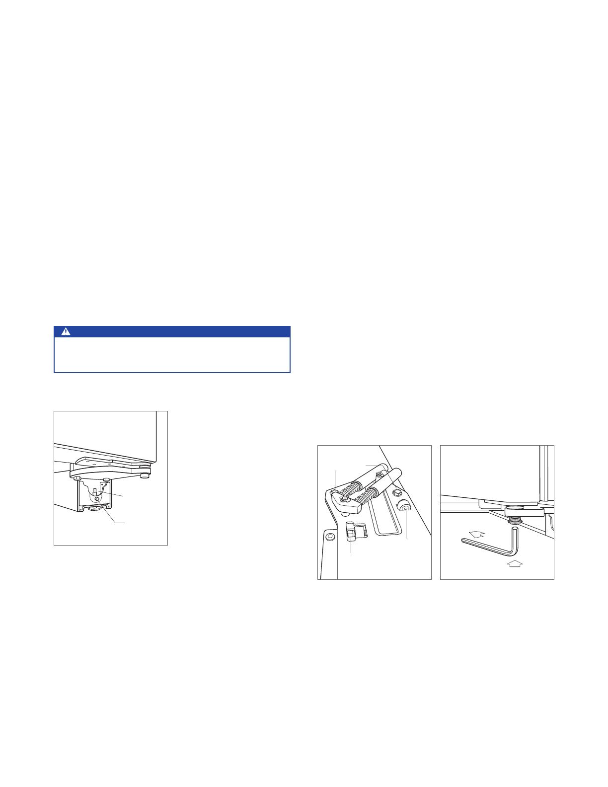
LEVELING
Once the unit is in position, turn the front leveling legs
clockwise to adjust the height. The rear height adjustment
can be made from the front of the roller base. Using a
3
/8"
socket, turn the
3
/8" hex bolt clockwise to raise the unit or
counterclockwise to lower. Use the lowest torque setting
when using a power drill. Do not turn the rear leveling legs
by hand. Refer to the illustration below.
When the unit is properly leveled, door and drawer adjust-
ments are less likely to be necessary.
IMPORTANT NOTE: Level the unit to the oor, not sur-
rounding cabinetry. This could affect the operation of the
unit, such as door closing.
WARNING
To reduce the possibility of the unit tipping forward, the
front leveling legs must be in contact with the oor.
FRONT
LEVELING LEG
REAR
ADJUSTMENT
Rear roller base adjustment.
UPPER
HINGE BOLTS
SIDE-TO-SIDE
TILT ADJUSTMENT
IN-AND-OUT
ADJUSTMENT
Door adjustment bolts.
Up-and-down door adjustment.