Page is loading ...

7001135 12/15 Rev. 35
DO NOT DISCARD THIS MANUAL: Retain for future use
If this heater is not properly installed,
result. For safety, follow all installation,
operation and maintenance directions.
Contact local building officials about
restrictions and installation inspection
requirements in your area.
SAFETY NOTICE
The French language version of this manual is available online: www.vermontcastings.com
La version française de ce manuel est disponible en ligne : www.vermontcastings.com
Catalytic Convection Heater
Installation and Operating Manual
Models 2460, 2461, 2462

2
Dutchwest
®
7001135
PLEASE NOTE
Please read this entire manual berfore you install
and use your new room heater. Failure to follow
instructions my result in property damage, bodily
injury or loss of life. Save these instructions for
future use.
The Dutchwest models covered in this Owner’s Guide have been tested and listed by OMNI
- Test Laboratories, Portland, Oregon. The test standards utilized were ANSI/UL 1482 for the
United States and ULC S627 for Canada. Dutchwest models are not listed for mobile home
installations.
Patents: U.S. - D288357, 4502395, 4646712;
Canada - 1235969. Other foreign mechanical patents
issued.
Accessories
• Bottom Heat Shield
• Clearance-reducing Rear Heat Shields
• Clearance-reducing Heat Shields for single-wall
stove pipe
• 2" legs
• Warming shelves (Small and Large Heaters only)
• Two-speed convection blower
• Automatic thermostat for the blower
Table of Contents
............................................................ 3
Installation ..........................................................4
Clearances .......................................................11
Assembly ..........................................................15
Smoke Alarm/Safety Tip ...................................16
Operation ..........................................................17
Maintenance .....................................................21
Replacement Parts ...........................................29
Warranty ...........................................................31
Proposition 65 Warning: Fuels used in gas, woodburn-
-
tion of such fuels, contain chemicals known to the State
of California to cause cancer, birth defects and other
reproductive harm.
California Health & Safety Code Sec. 25249.6

3
Dutchwest
®
7001135
1. Maximum burn times and heat outputs are based on laboratory testing using full loads of seasoned hardwoods, and may vary in individual use
depending on how the stove is operated, type and moisture content of fuels, and other factors. Maximum burn times are achieved under different
operating conditions than are maximum heat outputs.
2. These values are based on operation in building code-conforming homes under typical Winter climate conditions in the northeastern U.S. If your
home is of nonstandard construction (e.g. unusually well-insulated, not insulated, built underground, or if you live in a more severe or more temperate
expectations for your home.
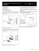
A
C
B
D
G
F
E
Fig. 1
Stove Model Number 2460 2461 2462
A 22" (560 mm) 25
3
4" (654 mm) 28
1
4" (717 mm)
B 21" (530 mm) 24
1
2" (620 mm) 27" (690 mm)
C 29
3
4" (754 mm) 30" (760 mm) 33" (840 mm)
D 16" (410 mm) 16" (410 mm) 18
1
4" (467 mm)
E 14
3
4" (375 mm) 14
5
8" (380 mm) 17" (430 mm)
F 26
3
4" (683 mm) 27" (690 mm) 30
1
8" (763 mm)
G 29
3
4" (754 mm) 30" (760 mm) 33" (840 mm)
Log length: 19" (480 mm) 22" (560 mm) 25" (640 mm)
Maximum burn time
1
: 8 hrs. 9 hrs. 12 hrs.
Average area heated (sq. ft.)
2
: 700-1,400 (65-130m
2
) 800-1,600 (75-150m
2
) 1,200-2,400 (112-224m
2
)
Range of heat output
4
: 7,800 - 26,800 Btu/hr. 11,300 - 26,800 Btu/hr. 10,500-27,700 Btu/hr
5
Maximum heat output: 35,000 Btu/hr. 40,000 Btu/hr. 55,000 Btu/hr.
4
(g/h, catalytic): 1.1 1.4 1.3
6
81% 77% 76%
Weight: 380 lbs. (172 kg) 436 lbs. (198 kg) 634 lbs. (288 kg)
Loading: Side or front Side or front Side or front
Flue exit position (reversible): Top or rear Top or rear Top or rear
Air controls: 2 controls 2 controls 2 controls

4
Dutchwest
®
7001135
Installation
SAFETY NOTICE:
IF YOUR DUTCHWEST CONVECTION HEATER IS NOT
PROPERLY INSTALLED, OPERATED AND MAINTAINED,
A HOUSE FIRE MAY RESULT. FOR SAFETY, FOLLOW
ALL INSTALLATION, OPERATION AND MAINTENANCE
DIRECTIONS. CONTACT LOCAL BUILDING OFFICIALS
ABOUT RESTRICTIONS AND INSTALLATION INSPEC-
TION REQUIREMENTS IN YOUR AREA.
Before you begin the installation, review your plans to
• Your stove and chimney connector will be far enough from
combustible material to meet all clearance requirements.
properly to meet all requirements.
• You have obtained all necessary permits from local
authorities.
your installation as safe and for determining that it meets
local and state codes.
Clearance and installation information is printed on the
metal label attached to the rear of the stove. Local authori-
ties generally will accept the label as evidence that, when
the stove is installed according to the information on the
label and in this manual, the installation meets codes and
can be approved.
Codes vary in different areas, however. Before starting
the installation, review your plans with the local building
authority. Your local dealer can provide any additional
information needed.
Important: Failure to follow these installation instructions
may result in a dangerous situation, including a chimney
allow makeshift compromises to endanger property and
personal safety.
Chimney Types
Your Dutchwest Convection Heater must be connected
to a sound masonry chimney that meets local codes, a
relined masonry chimney that meets local codes, or to an
approved prefabricated metal chimney. Whatever kind you
use, the chimney and chimney connector must be in good
condition and kept clean.
Masonry Chimneys
If you use an existing masonry chimney, it must be inspect-
ed to ensure safe condition before the stove is installed.
Your local professional chimney sweep, building inspector,
inspection or to direct you to someone who can.
-
ing. Do not use an unlined chimney. The chimney should
also be examined for cracks, loose mortar, other signs of
deterioration, and blockage. Repair any defects before the
chimney is used with your stove.
Unused openings in an existing masonry chimney must
be sealed with masonry to the thickness of the chimney
wall, and the chimney liner should be repaired. Openings
be sealed with mortar or refractory cement. In the event
these unused thimbles.
The chimney should be thoroughly cleaned before use.
A newly-built masonry chimney must conform to the
standards of your local building code or, in the absence
chimneys must be lined, either with code-approved ma-
sonry or pre-cast refractory tiles, stainless steel pipe, or
a code-approved, “poured-in-place” liner. The chimney’s
clean-out door must seal tightly.
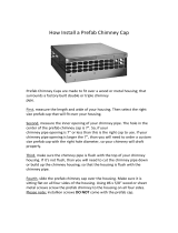
Prefabricated Double-Wall
Insulated Chimney
Tile Lined
Masonry
Chimney
ST241
Fig. 2 If in sound condition and approved for use, either a ma-
sonry or a prefabricated chimney may be used.

5
Dutchwest
®
7001135
Prefabricated Chimneys
A prefabricated metal chimney must be one tested and
listed for use with solid-fuel burning appliances.
(20 mm per meter) from the stove toward the chimney.
feet (1m) and the total length of chimney connector should
be no longer than 8 feet (2.5m).
Chimney Height
For proper draft and good performance, the chimney should
The chimney must also extend at least 3’ (900 mm) above
the highest point where it passes through a roof, and at
least 2’ (600 mm) higher than any portion of a building
within 10’ (3 m). (Fig. 3)
DO NOT CONNECT THIS UNIT TO A CHIMNEY FLUE
SERVING ANOTHER APPLIANCE.
Chimney Size
The Model 2460 and 2461 heaters should be vented into
8” x 8” (200 mm x 200 mm) square, or 8” (200 mm) round.
Chimney liners larger than 8” x 12” (200 x 300 mm) may
promote rapid cooling of smoke and reduction in draft,
especially if they are located outside the home. These
large chimneys may need to be insulated or have their
Accessories to help make the connection between stainless
steel chimney liners and the stove are available through
your local dealer.
2' MIN.
2' MIN.
3'
MIN.
0 TO 10'
3'
MIN.
0 TO 10'
Reference
Point
AC246
Fig. 3 The 2/3/10 rule for chimneys.
Guidelines for Installing
the Chimney Connector
The chimney connector is the single-wall pipe, or listed and
approved double-wall pipe that connects the stove to the
chimney. The chimney itself is a masonry or prefabricated
used only to make the connection from the stove to the
chimney.
Do not pass the chimney connector through a combustible
wall or ceiling, or through an attic, a closet or any similar
concealed space. If passage through a combustible wall
is unavoidable, follow the recommendations in the follow-
ing section on Wall Pass-Throughs. Keep the passage
as short and direct as possible, with no more than two 90
degree turns.
Two Types of Connector
You may use either a single-wall steel connector of the
double-wall connector.
Single-Wall Connector
The single-wall chimney connector should be made of 24
gauge or heavier steel, and must have a minimum internal
diameter of 6” (150 mm) for models 2460 and 2461, or 8”
(200 mm) for model 2462.
Install single-wall chimney connector not less than 18” (450
mm) from the ceiling.
In cathedral ceiling installations, extend the prefabricated
chimney downward to within 8 feet (2.5 meters) of the
stove. The entire chimney connector should be exposed
and accessible for inspection and cleaning.
withstand the high temperatures that can be reached by
smoke and exhaust gases and it may release toxic fumes
under high heat.
Chimney
Slip Pipe
Standard Connector
Flue Liner
Flue
Thimble
Flue Collar
Floor Protector
ST418
Fig. 4 Sections of a steel chimney connector of at least 24 gauge
thickness are fastened together with screws to
connect the stove to the chimney.

6
Dutchwest
®
7001135
Double-Wall Connector
Information on assembling and installing double-wall con-
nectors is provided by the manufacturer of the double-wall
pipe. Follow the manufacturer’s installation instructions
exactly. Most manufacturers of prefabricated double-wall
insulated chimneys also offer double-wall connector pipes.
Using a chimney and connector pipe from the same man-
ufacturer helps simplify the assembly and installation.
NOTE: For installations using double-wall connectors,
minimum clearances must conform to listed clearances
in the Stove and Chimney Connector Clearance Charts
on page 11 and 12 of this manual.
Assembling Single-Wall
Chimney Connector
SAFETY NOTE: Always wear gloves and safety goggles
when drilling, cutting or joining sections of chimney
connector.
For double-wall connectors, follow the manufacturer’s
instructions exactly. For single-wall connectors, follow the
instructions below.
1.
#10 x 1/2” sheet metal screws.
Toward
Stove
Flue Gas
Direction
ST242
Fig. 5 Crimped sections always point toward the stove so that
any liquid condensation will not leak out.
See the clearance charts on pages 11 and 12.
NOTE: Special slip pipes and thimble sleeves that form
telescoping joints between sections of chimney connector
are available to simplify installations. They can eliminate
the need to cut individual connector sections. Consult your
local dealer about these special pieces.
Securing the Connector
to a Prefabricated Chimney
Follow the installation instructions of the chimney manufac-
turer exactly as you install the chimney. The manufacturer
of the chimney will supply the accessories to support the
chimney, either from the roof of the house, at the ceiling of
the room where the stove is installed, or from an exterior wall.
Special adaptors are available from your local dealer to
make the connection between the prefabricated chimney
and the chimney connector. (Fig. 6) The top of such
adaptors attach directly to the chimney or to the chimney’s
ceiling support package, while the bottom of the adaptor
is screwed to the chimney connector.
creosote falling from the inner walls of the chimney will
stay inside the chimney connector.
Prefab (Insulated)
Chimney
Ceiling Support
Package
Prefab Chimney
Adapter
Chimney Connector
(Stovepipe)
ST419
Fig. 6 Joining the chimney connector to a prefabricated chim-
ney.
2. Secure each joint between sections of chimney connec-
tor, including telescoping joints, with at least three sheet
metal screws.
3. Secure the chimney connector to the chimney. Instruc-
tions for various installations follow below.
4
.
are correct distances from nearby combustible material.
Securing the Connector
to a Masonry Chimney
The Dutchwest Convection heaters may be connected
to either a freestanding masonry chimney or a masonry
Freestanding Installations
If the chimney connector must pass through a combustible
wall to reach the chimney, follow the recommendations in
the wall pass-through section that follows.

7
Dutchwest
®
7001135
“breech”) must be lined with either a ceramic or metal
cylinder, called the “thimble”, which is securely cemented
in place. (Fig. 7) Most chimney breeches incorporate
Flue Liner
-
nector to the First Tile of
the Flue Liner
Observe
Miniumum Clearances
Damper
Plate is
Remvoed
or Locked
in Open
Position
Close Off
the Damper
Opening with
Sheet Metal
and Sealant
ST245a
Fig. 9
are available from your local dealer.
Masonry Wall
Ceramic Flue Liner
Chimney Connec-
tor Shield
Block-Off Plate
Chimney Connector
ST244a
Fig. 8
clearance between the chimney connector and either the mantel
and/or the ceiling is inadequate, special protective shields will
be required.
Thimble
Sleeve
Flue
Keep
Sleeve
with Flue
Tile
Thimble
Flue Liner
Chimney
Connector
ST243
Fig. 7 The thimble, made of either ceramic or metal, must be
cemented in place securely.
A special piece called the “thimble sleeve,” slightly smaller
in diameter than the standard connector and most thimbles,
will ease the removal of the chimney connector system for
inspection and cleaning. Thimble sleeves should be avail-
able from your local dealer.
To install a thimble sleeve, slide it into the breech until it is
The thimble sleeve should protrude 1-2" (25-50 mm) into
the room. Use furnace cement and thin gasketing to seal
the sleeve in place in the thimble. Secure the chimney
connector to the outer end of the sleeve with sheet metal
screws.
Fireplace Installations -
Above the Fireplace
In this installation, the chimney connector rises from the
-
extend at least to the point at which the chimney connector
enters the chimney. Follow all the guidelines for installing
a chimney connector into a freestanding masonry chimney,
and pay special attention to these additional points:
• Check the stove and chimney connector clearances to
combustible mantel or trim materials. Use the neces-
sary combination of mantel, trim, and connector heat
shields to provide the required clearances. (Fig. 8)
• Double-check connector clearance from the ceiling.
•
the draft. However, it must be possible to re-open the
damper to inspect or clean the chimney.
Fireplace Installations -
Through the Fireplace
The Convection heaters may be installed either without
- depending on the safety regulations that apply to your
preference. For either situation, the chimney connector/
positive connection kit extends back from the stove, en-
In such installations, a “positive connection” must be made
-

8
Dutchwest
®
7001135
tion provisions must be observed. These provisions are
discussed in the Clearance and Floor Protection sections
respectively.
Wall Pass-Throughs
Whenever possible, design your installation so the con-
nector does not pass through a combustible wall. If you
must use a wall pass-through in your installation, check
with your building inspector before you begin and construct
it in accordance with local building codes. Also check
requirements.
Accessories are available for use as wall pass-throughs.
If using one of these, make sure it has been tested and
listed for use as a wall pass-through.
distance from the single-wall connector to provide the
required 12" (305 mm) clearance for the connector. Any
material used to close up the opening must be noncom-
bustible.
The following wall pass-through methods may be approved
in your area:
• Use a section of listed factory-built chimney with a
nine-inch clearance to combustibles.
• Place a chimney connector pipe inside a ventilated
thimble, which is then separated from combustibles by
In Canada: The Canadian Standards Association has
established different guidelines. Figure 11 shows one
method, in which all combustible material in the wall is cut
away to provide the required 18" (450 mm) clearance for
the connector. The resulting space must remain empty.
on one
side only. If covers must be used on both sides, each cover
must be mounted on non-combustible spacers at least 1”
(25 mm) clear of the wall. Your Dutchwest dealer or your
local building inspector can provide details of other ap-
proved methods of passing a chimney connector through a
combustible wall. In Canada, this type of installation must
conform to CAN/CSA-B365, Installation Code for Solid Fuel
NOTE: Do not vent your Dutchwest stove into a factory-
adapt them for any other use.
diameter 2 inches (51 mm) larger than the chimney con-
nector and having 1 inch (25.4 mm) or more of insulation
and maintaining a minimum 2 inch air space between
the outer wall of the chimney and combustibles.
18”
(450mm)
All Around
the Chimney
Connector
Sheet Metal
Cover
(One side
only)
ST421
Fig. 11 Hollow wall pass-through.
Chimney Con-
nector
12”
(305mm)
12”
(305mm)
ST420
Fig. 10 Wall pass-through enclosed with noncombustible
materials.
• If the stove is installed without legs, we recommend
the use of noncombustible tiles or pavers as shims to
stove. Make sure not to block air slots instove bottom
with shims or remove fan cover.
• Place a chimney connector pipe inside a section of listed
solid-insulated, factory-built chimney, with an inside
DO NOT CONNECT THE HEATER TO ANY AIR DIS-
TRIBUTION DUCT OR SYSTEM.
Floor Protection
A tremendous amount of heat radiates from the bottom plate
around the stove will require protection from radiant heat
as well as from stray sparks or embers that may escape
Castings Group Bottom Heat Shield. Spark and ember

9
Dutchwest
®
7001135
Most installations will require that the bottom heat shield be
attached. Only when the stove is placed on a completely
noncombustible surface such as unpainted concrete over
earth may it be used without the heat shield.
-
lation with the heat shield attached, use a noncombustible
may be covered with a decorative noncombustible material
if desired. Do not obstruct the space under the heater.
Protection requirements vary somewhat between the United
States and Canada as follows:
stove and must extend at least 16 inches from the front and
left (loading door) side of the stove, and at least 6 inches
from the right side and rear. (Fig. 12) Refer to Figure 12
for each stove model.
inches (457mm) from the front and left (loading door) side
of the stove, and at least 8 inches (203mm) from the right
side and rear. (Fig. 12)
ST422
Fig. 12-
ments on all four sides of the stove.
Minimum Dimensions for Noncombustible Floor
Protectors (Depth x Width):
Model U.S. Canada
2460 38" x 44" 42" x 48" (1067mm x 1219mm)
2461 38" x 48" 42" x 52" (1067mm x 1320mm)
2462 42" x 52" 46" x 56" (1168mm x 1422mm)
B
B
A
A
U.S. Canada
A. 16" 18" (457 mm)
B. 6" 8" (203 mm)
A
ST423
Fig. 13 Combustible supporting timbers (A) may lie beneath
-
tion.
call for more protection on the left side than on the right. If
you wish a more balanced look, increase the other side of
the hearth as well. Do not reduce side protection under
any circumstances.
Fireplace Installations
You may install your Dutchwest Convection Heater in an
the standard legs attached.
-
-
bustible” requirement because the brick or concrete hearth
heavy wooden framing as in Figure 13. Because heat
passes readily through brick or concrete, it can easily pass
You may not install a
heater on a combustible hearth without legs. Standard
leg installations must include the bottom heat shield.
for freestanding installations.
Floor Protection for Fireplace
Installations with Standard Legs
Fireplace installations with the standard legs and the bot-
1/4" non-asbestos mineral board or equivalent, or 24 gauge
sheet metal (that may be covered with a decorative non-
extend at least 16" (406 mm) [18" / 457 mm in Canada]
from the front of the stove and from the left (loading door)
side, and at least 6" (152 mm) from the right side and rear.
of the chimney connector, including 2" to either side.

10
Dutchwest
®
7001135
Fireplace Installation Clearances
the:
• Side of the stove and the right and left walls
• Side of the stove and the decorative side trim on the
• Top of the stove and the mantel
In addition, both Fireplace Adaptor and Fireplace Insert
are addressed in the section on Floor Protection.
S
M
M
T
Model: 2460 2461 2462
Side Walls (S) 20" (510mm) 24" (610mm) 23" (580mm)
Trim (T) 12" (300mm) 12" (300mm) 12" (300mm)
Mantel (M) 20" (510mm) 20" (510mm) 20" (510mm)
ST426
Fig. 15-
mended clearances must be maintained between stove and the
surrounding combustible components.
Many raised hearths will extend less than the required
distance from the front of the heater when it is installed.
above, must be added to extend the hearth 16" (406 mm)
[18" (457 mm) in Canada].
-
tection.
requirements to the side walls, side decorative trim, and
Installation Clearances” in this section.
REMINDER- FIREPLACE INSERT INSTALLATIONS
WITHOUT LEGS ARE PERMISSIBLE ONLY IF THE
HEARTH IS COMPLETELY NONCOMBUSTIBLE, SUCH
AS UNPAINTED CONCRETE OVER EARTH.
Keep the Stove a Safe Distance
From Surrounding Materials
Both a stove and its chimney connector radiate heat in all
directions when operating. A safe installation requires that
adequate clearance be maintained between the stove and
nearby combustible materials to ensure that such materials
do not overheat.
Clearance is the distance between either your stove or
and other combustible materials away from the stove as
well. In general, a distance of 48" (1220 mm) must be main-
tained between the stove and moveable combustible items
etc. Keeping those clearance areas empty assures that
nearby surfaces and objects will not overheat.
Safe Ways To Reduce Clearances
been established through careful research and testing to
UL and ULC standards.
Clearance requirements have been established to meet
every installation possibility, and they involve the combina-
tion of basic variables:
• When the stove has no listed heat shield
• When the stove has a listed heat shield
• When the wall has no heat shield
• When the wall has a heat shield
• When the stove has a double-wall chimney connector.
• When the stove has a single-wall connector wit heat
shields, or without heat shields.
In general, the greatest clearance is required when you
locate a stove with no heat shield near a wall with no heat
shield. The least clearance is required when both the
stove and the wall have heat shields. Reducing a stove
clearance may require a listed heat shield on the chimney
connector as well, or a double-wall connector.
Clearances may be reduced only by means approved
by the regulatory authority and in accordance with the
clearances listed in this manual. The charts and sample
installations that follow list all the clearances required for
-
vection Heaters.
Fig. 14
hearth, even if your stove is installed with the legs and the bot-
tom heat shield.
ST424

11
Dutchwest
®
7001135
Designing a Safe Installation
The section that follows contains charts with the information
that you’ll need to make your installation safe. Included
are a chart to tell you exactly where to cut the hole in the
ceiling so that the stove will meet clearance requirements,
a chart that gives stove clearances for all installations,
for various installations.
Refer to these charts as you plan the installation and do
not compromise on any of the dimensions listed.
Clearance Chart Reference Diagrams
Refer to the diagrams below when using the Stove and
Chimney Connector Clearance Chart which follows. For
example, the letter “A” gives the minimum side clearance
for installations in which the stove is not equipped with
a rear heat shield and the wall beside the stove is not
protected. “D” gives the minimum side clearance when
the stove does not have a rear heat shield, but the wall
is protected.
Measure clearance distances from the top plate of the stove
or chimney connector to the wall, not the wall protector.
B
A
C
C
H
G
N/A
E
D
F
F
J
I
N/A
O
N
P
P
L
K
M
M
Unprotected Surfaces Protected Surfaces
Parallel Installations Corner Installations Parallel Installations Corner Installations
Installations with no stove heat shields
Rear exit, rear heat shield installations
Top exit, rear heat shield and chimney connector heat shields or double wall connector
ST255a

12
Dutchwest
®
7001135
1. Shielding for a top exit stove must include a shield insert to protect the
2. Chimney connector heat shields must extend exactly 24" (610 mm)
3. Model 2462 Only: All installations using single wall connector pipe with
connector heat shield straight up to a factory built chimney require a 24"
(610 mm) diameter or square ceiling heat shield. The ceiling heat shield
Stove and Chimney Connector Clearance Charts
Stove Clearance Side Rear Corner Side Rear Corner
No heat shields [A] 22" (560 mm) [B] 24" (610 mm) [C] 18" (460 mm) [D] 12" (300 mm) [E] 14" (360 mm) [F] 10" (250 mm)
Rear exit, rear h.s. [G] 22" (560 mm) [H] 14" (360 mm) N/A [I] 12" (300 mm) [J] 12" (300 mm) N/A
Top exit
1
, rear h.s.
Single-wall connector [K] 22" (560 mm) [L] 24" (610 mm) [M] 18" (460 mm) [N] 12" (300 mm) [O] 14" (360 mm) [P] 10" (250 mm)
No connector h.s.
Top exit
1,2
, rear h.s.
Single-wall connec- [K] 22" (560 mm) [L] 14" (360 mm) [M] 15" (380 mm) [N] 12"(300 mm) [O] 12" (360 mm) [P] 8" (200 mm)
tor with connector h.s.
Top exit
1
, rear h.s.
Double-wall connector [K] 22" (560 mm) [L] 19" (480 mm) [M] 15" (380 mm) [N] 12" (300 mm [O] 11" (280 mm) [P] 8" (200 mm)
Chimney Connector Clearance:
Single-wall connector 19" 480 mm) 9" (230 mm)
No connector h.s
Single-wall
2
connector 9" (360 mm) 7" (180 mm)
With connector h.s.
Double-wall connector 14" (360 mm) 6" (150 mm)
Front Clearance to Combustibles: 48" (1220 mm) (All Installations)
Model 2460 Small Convection, and Model 2461 Large Convection:
UNPROTECTED SURFACES PROTECTED SURFACES
Corner Corner
Parallel Installations Installations Parallel Installations Installations
Model 2462 Extra-Large Convection:
Stove Clearance Side Rear Corner Side Rear Corner
No heat shields [A] 20" (510 mm) [B] 23" (580 mm) [C] 18" (460 mm) [D] 18" (460 mm) [E] 18" (460 mm) [F] 17" (430 mm)
Rear exit, rear h.s. [G] 20" (510 mm) [H] 18" (460 mm) N/A [I] 18" (460 mm) [J] 12" (300 mm) N/A
Top exit
1
, rear h.s.
Single-wall connector [K] 20" (510 mm) [L] 23" (580 mm) [M] 18" (460 mm) [N] 18" (460 mm) [O] 18" (460 mm) [P] 17" (430 mm)
No connector h.s.
Top exit
1,2,3,4
, rear h.s.
Single-wall connec- [K] 20" (510 mm) [L] 18" (460 mm) [M] 17" (430 mm) [N] 18" (460 mm) [O] 12" (300 mm) [P] 15" (380 mm)
tor with connector h.s.
Top exit
1
, rear h.s.
Double-wall connector [K] 20" (510 mm) [L] 14" (360 mm) [M] 16" (410 mm) [N] 18" (460 mm) [O] 12" (300 mm) [P] 15" (380 mm)
Chimney Connector Clearance:
Single-wall connector 18" (460 mm) 13" (330 mm)
No connector h.s
Single-wall
2
connector 13" (330 mm) 7" (180 mm)
With connector h.s.
Double-wall connector 8" (200 mm) 6" (150 mm)
Front Clearance to Combustibles: 48” (1220 mm) (All Installations)
UNPROTECTED SURFACES PROTECTED SURFACES
Corner Corner
Parallel Installations Installations Parallel Installations Installations
should be 24 gauge sheet metal or equivalent mounted on 1" (25 mm)
non-combustible spacers 1" (25 mm) below ceiling.
4. Chimney connector heat shields must extend to within 1" (25 mm) or
less of the ceiling heat shield for installations venting straight up to a facto-
ry-built chimney. In top exit installations using an elbow to vent to the rear,
the chimney connector must be shielded over the entire vertical length.
5. If a single-wall oval-to-round adaptor is used, a shield must be used to
protect combustibles to the rear of the adaptor.

13
Dutchwest
®
7001135
Distance from Center of Flue Collar to Wall in Top-Exit Installations
Dutchwest Convection Heaters equipped with rear heat shields
A
B
C
E
D
F
Chimney Connector Side Rear Corner Side Rear Corner
MODEL 2460 (Small Convection)
Listed, Approved
Double-wall [A] 33" (840 mm) [B] 18" (460 mm) [C] 25" (640 mm) [D] 23" (580 mm) [E] 10" (250 mm) [F] 15" (380mm)
Single Wall, with
Connector Heat Shields [A] 33" (840 mm) [B] 13" (330 mm) [C] 22" (560 mm) [D] 23" (580 mm) [E] 11" (580 mm) [F] 15" (380 mm)
Single Wall, without
Connector Heat Shields [A] 33" (840 mm) [B] 23" (580 mm) [C] 25" (640 mm) [D] 23" (580 mm) [E] 13" (330 mm) [F] 17" (430 mm)
MODEL 2461 (Large Convection)
Listed, Approved
Double-wall [A] 35" (890 mm) [B] 18" (460 mm) [C] 27" (690 mm) [D] 25" (640 mm) [E] 10" (250 mm) [F] 17" (430 mm)
Single Wall, with
Connector Heat Shields [A] 35" (890 mm) [B] 13" (330 mm) [C] 24" (610 mm) [D] 25" (640 mm) [E] 11" (280 mm) [F] 17" (430 mm)
Single Wall, without
Connector Heat Shields [A] 35" (890 mm) [B] 23" (580 mm) [C] 27" (690 mm) [D] 25" (640 mm) [E] 13" (330 mm) [F] 19" (480 mm)
MODEL 2462 (Extra-Large Convection)
Listed Approved
Double-Wall [A] 35" (890 mm) [B] 13" (330 mm) [C] 26" (660 mm) [D] 33" (660 mm) [E] 11" (280 mm) [F] 25" (640 mm)
Single Wall, with
Heat Shields [A] 35" (890 mm) [B] 17" (430 mm) [C] 29" (740 mm) [D] 33" (840 mm) [E] 11" (280 mm) [F] 25" (640 mm)
Single Wall, without
Heat Shields [A] 35" (890 mm) [B] 22" (560 mm) [C] 33" (840 mm) [D] 33" (840 mm) [E] 17" (430 mm) [F] 27" (690 mm)
UNPROTECTED SURFACES PROTECTED SURFACES
Corner Corner
Parallel Installations Installations Parallel Installations Installations
ST427

14
Dutchwest
®
7001135
Wall Heat Shield Dimensions
Dutchwest Convection Heaters, Models #2460 (Small), #2461 (Large), and #2462 (Extra Large)
ST428
60”
(1525mm)
48”
(1220mm)
36” (910mm)
Centered Behind Stove
Fig. 16 Rear wall protection.
Spaced 1”
(25mm)
from Floor
48”
(1220mm)
60” (1525mm)
Spaced 1”
(25mm)
from Floor
ST429
Fig. 17 Sidewall protection.
60”
(1525mm)
48”
(1220mm)
Spaced 1”
(25mm)
from Floor
ST430
Fig. 18 Corner wall protection.
Wall Shields
Meet at
Corner

15
Dutchwest
®
7001135
Your convection heater requires some assembly. Follow
the directions carefully and refer to the parts diagram at
the back of this manual.
CAUTION: The Dutchwest Convection Heater is very heavy.
To prevent personal injury or damage, either to the stove or
your home, have two or more people to help move it.
Unpack the Parts
Check to make sure all the parts are included and intact.
You should have received:
• 1 fully assembled heater body, (with catalytic burner
installed at the factory)
• 4 legs (may be pre-attached by the manufacturer)
• 1 ash pan
• 1 probe thermometer
• 1 handle assembly
• 1 strip of Interam™ gasket (for the catalytic burner)
• 1 hardware bag, containing the following parts:
• (3) #10 x 1/2" sheet metal screws, (to attach the
• (1) 1/8" Allen wrench, (to tighten the door latch)
• (1) 5/32" Allen wrench, (to tighten the damper handle)
• (4) washers, (used with the leg bolts to attach legs to
the stove)
• (1) door handle insert holder for storing the handle
assembly when it is not in use.
The four hex-head leg bolts have been installed in the ap-
propriate holes in the bottom of the stove.
If any parts are missing or damaged, immediately notify
your Dutchwest dealer for replacements. Do not install
your stove without having all necessary parts or by using
damaged parts.
* A Bottom Heat Shield is required in many installations.
Installation Section of this manual.
If your stove was not shipped with legs -
Attach the Legs and Bottom Heat Shield
NOTE: If heat shields are not properly installed and main-
-
tions and installation inspection requirements in your area.
1. Place the stove on its back. Tilt it carefully, it is heavy.
Use 4 x 4 blocking to make it easier to tilt the stove.
2. The tops of the legs are slotted. Remove each leg bolt
from the bottom of the stove and then replace it with a
heat shield bracket and a washer. Place the door handle
insert holder on the bolt for the left rear or either front
leg. (Fig. 19)
Assembly
Left Leg
Door
Handle
Holder
Heat
Shield
Bracket
Hex Head Bolt
& Washer
ST431
Fig. 19 To attach the legs, remove the bolts from the stove bot-
tom and reassemble with the handle holder, heat shield brackets
(if necessary) and washers.
3. Slide the leg into position around the bolt and fasten it
-
ets using the four (4) 1/4-20 x 1/2" bolts with nuts.
IMPORTANT: For heat shields with one side painted, the
-
tion.
5. Adjust the bracket’s position on each leg as needed
6. Use a 7/16" wrench to tighten the shield securely to
the brackets and a 9/16" wrench to tighten the leg bolts
securely to the stove.
7. Carefully raise the stove onto its legs.
Bottom Heat Shield
ST912
Fig. 20 Bottom heat shield in place on bottom of stove.

16
Dutchwest
®
7001135
Smoke and CO Detectors
Safety Tips
The use of smoke and carbon monoxide (CO) detectors
throughout the home is strongly advised, even if not re-
quired by building codes or insurance regulations. It is
a good idea to install a smoke detector in the living ar-
eas and each bedroom. Follow the smoke/CO detector
manufacture's placement and installation instructions and
maintain regularly.
You may not, however, wish to install a detector in the im-
mediate vicinity of the stove. Depending on the sensitivity
of the unit, the alarm can be set off while you are tending
the same room, locate it as far away from the stove as
possible.
-
and is clearly visible. All occupants of the house should
know where it is, and how it operates. Have heavy stove
gloves available near the stove. Have special safety ac-
cessories (e.g., Child Guard Screen) available for use if
small children will be in the home.
tight, (damper, primary air, all doors) will help to smoth-
• Inspect your stove, stove pipe and chimney for any
before using your stove again.

17
Dutchwest
®
7001135
Heater Controls and Features
Air Controls
The Dutchwest Convection Heater has two air controls that
regulate the amount of air drawn into the stove. Generally,
faster, while less air decreases heat output while prolonging
the overall burn time.
The Primary Air control lever is located at the lower front
edge of the left side (looking from the front of the stove).
(Fig. 21) The lever operates the two air inlet shutters which
are on the front of the stove. Opening the inlet shutters
provides air for primary combustion.
To open the shutters, turn the lever counterclockwise. The
shutters are all the way open when the lever points toward
the front at a ”4:30” position. (Fig. 22) To close the shutters,
turn the lever clockwise. The shutters are fully closed when
the lever points straight down. (Fig. 23)
The secondary air inlet, over the side door, admits air to
the catalytic combustor only,
combustor temperatures. Use a gloved hand or the metal
tip of the door handle to adjust this inlet. Opening or clos-
1
2 to 2
ST434
Fig. 23 Closing the primary air supply.
Air Inlet
Shutter
Pull Control
Lever Forward
to Open Air
Shutters
ST433
Fig. 22 Opening the primary air supply.
Damper
Secondary
Air Inlet
Side Loading
Door
Primary
Air Control
Lever
Front
Loading Door
ST432
Fig. 21 The heater controls.
Operation
This wood heater has a manufactured-set minimum low
burn rate that must not be altered. It is against federal
regulations to alter this setting or otherwise operate this
wood heater in a manner inconsistent with operating
instructions in this manual.
WARNING

18
Dutchwest
®
7001135
Damper Function
The Damper is operated by moving the handle on the upper
gases pass through an insulated catalytic burner before
Use the door insert handle to rotate the damper handle.
Turn it counterclockwise to open the damper and clockwise
to close it. You will feel resistance as the damper mecha-
nism engages into the open (counterclockwise) position.
The stove damper must
fuel, or before you open either door for any reason.
Load Doors
A Side Loading Door allows the easiest loading of wood
logs. The Front Door opens for adding an occasional log
opening either door.
Successful Wood Burning
Woodburning is often said to be more of an art than a
science. You’ll easily master the art if you start by using
good, dry fuel and by understanding how the stove’s air
supply system operates.
Burn Only High-Quality Fuel
Your heater is designed to burn natural wood only. Do
not burn other fuels. Never burn pressure-treated wood,
painted or stained wood, or glossy newsprint.
-
wax) in this appliance. Never burn liquid-based fuels
such as kerosene, gasoline or alcohol.
Burning any materials not allowed in these instruc-
burning air-dried, seasoned woods as compared to soft-
woods or freshly cut hardwoods. Avoid burning “green”
wood that has not been properly seasoned. Do not burn
construction materials; they often contain chemicals and
metals that can damage the catalytic combustor or pollute
the air. Do not burn ocean driftwood; when it burns, the salt
it absorbs will attack the cast iron.
The best hardwood fuels include oak, maple, beech, ash,
and hickory that has been split, stacked, and air-dried out-
side under cover for at least one year. If hardwood is not
burned. They too should be properly dried. The length of
particular stove. Avoid using wood that has been dried
more than two years. Often gray in color, this wood burns
very quickly, resulting in short burn time and diminished
stove performance. If you must burn it, mix it in with greener
wood to slow the burn.
short-term storage, keep wood a safe distance from the
heater and keep it clear of the areas around the heater
used for refueling and ash removal.
Use the Air Control Settings
that Work Best for You
-
of the fuel, the amount of heat desired, and how long you
Control settings also depend on your par-
ticular installation’s “draft,” or the force that
moves air from the stove up through the
chimney. Draft is affected by such things as
the height, type, and location of the chimney,
local geography, nearby obstructions, and
other factors.
Too much draft may cause excessive tem-
peratures in the stove. On the other hand,
room and/or the “plugging” of the chimney
and catalytic burner.
How do you know if your draft is excessively
high or low? Symptoms of too much draft in-
clude an uncontrollable burn or a glowing-red
part of the stove or chimney connector. A
sign of inadequate draft is smoke leaking
into the room through the stove or chimney
connector joints.
Door Insert Handle
Open
ST435
Closed
ST436
Fig. 24 Damper operating positions.

19
Dutchwest
®
7001135
heat. It may take a week or two to determine the amount of
heat and the length of burn you should expect from various
control settings.
Notice that the probe thermometer on the stove top tells you
the temperature of the catalytic burner only; it does not tell
are very intense (far more intense than any other part of
You should put a magnetic surface thermometer on the
side door. This is the only single-thickness area of the
door more than any other.
-
courage creosote formation in the stovepipe and chimney;
higher temperatures can cause stove parts to burn out
prematurely. Always operate the stove according to
temperatures. Besides the air control, you can manage the
stove’s heat output and burn time by how much wood you
load at at a time.
In such instances, an open window near the stove on the
windward side of the house (side against which the wind
is blowing) will provide the fresh air needed.
Use the air control settings indicated in Figure 24 as a
starting point to help determine the best settings for your
installation.
DO NOT OPERATE THE STOVE WITH THE ASH DOOR
OPEN. OPERATION WITH THE ASH DOOR OPEN CAN
CAUSE AN OVERFIRING CONDITION TO OCCUR.
OVERFIRING THE STOVE IS DANGEROUS AND CAN
RESULT IN PROPERTY DAMAGE, INJURY, OR LOSS
OF LIFE.
How to Build and Maintain a Wood Fire
Loading Wood
Your Dutchwest Convection Heater accepts wood from both
the front and side. Front loading is useful for kindling a new
side loading as most convenient when adding several logs
at a time. Always be certain that the stove damper is open
before opening either door.
WARNING: OPERATE YOUR DUTCHWEST CONVEC-
TION HEATER ONLY WITH THE DOORS FULLY CLOSED
EXCEPT WHEN REFUELING.
THIS STOVE IS HOT WHILE IN OPERATION! KEEP
CHILDREN, CLOTHING, AND FURNITURE AWAY. CON-
TACT MAY CAUSE SKIN BURNS.
Break-in Fires
If your stove is new or has new cast iron replacement
continue with Step 4.
The stove’s paint and cement will emit a slight odor as these
provide extra ventilation near the stove by partially opening
a door or window when the odor is present.
Lighting the Fire
Step 1. Open the stove damper. Fully open the primary
air control and close the secondary (catalyst) air control.
Step 2. Lay some crumpled newspapers in the stove.
on the paper. On the kindling, lay two or three larger sticks
of split dry wood approximately 1-2” (25-50 mm) thick.
DO NOT USE CHEMICALS OR FLUIDS TO START THE
FIRE. DO NOT BURN GARBAGE OR FLAMMABLE FLU-
IDS SUCH AS GASOLINE, NAPTHA, OR ENGINE OIL.
Also, never use gasoline-type lantern fuel, kerosene, char-
the heater while it is in use.
Primary Air Catalyst Air
Position of primary air control
lever for different burn rates.
Low 1/2 turn open
Medium 1
1
2 turn open
High 1
1
2 to 2 turns open
Number of turns the air control
is open for different burn rates.
Fig. 25 Primary and Catalyst air settings.
High
Med.
Low
Closed
Notice that changes in the weather have a strong effect
on chimney draft. Higher outdoor temperatures and lower
air pressure both weaken draft; lower temperatures and
higher air pressure encourage a stronger draft. An excep-
tion to this is in installations with outdoor chimneys; since
these lose heat to the outdoors, it takes longer to warm
them up initally, and it takes more heat to keep them warm,
especially during very low temperatures outdoors.
Most installations do not require a large amount of com-
bustion air, especially if adequate draft is available. Do
altering the air control adjustment range outlined in these
directions.
In some newer homes that are well insulated and weather-

20
Dutchwest
®
7001135
Step 3.
should be well-established within 10-15 minutes. You may
gradually build it up by adding a few sticks at a time of a
live coal bed begins to form.
NOTE:
control because the stove is not yet heated to its optimum
temperature. One method of reducing emissions during a
cold start-up is the use of a “top-down” kindling procedure.
In this, place larger pieces of kindling on the bottom of the
kindling pile followed by smaller and smaller pieces as the
top. Light the kindling pile with a match at the top and allow
the kindling to burn downward into the larger pieces. This
creating an air-starved condition.
NOTE: An especially large, outdoor, or cold chimney
may need to be “primed,” or warmed up, before it will
a couple pieces of newspaper, place them on top of the
kindling and toward the back of the stove, light them, and
close the doors. This should heat the chimney enough to
initiate a draft.
Once the draft is established, open the front door and light
the rest of the fuel from the bottom. Do not light the main
bed of fuel until the chimney begins drawing. Repeat the
procedure as often as necessary if the initial attempt is
unsuccessful.
Step 4.
30 minutes) close the stove damper.
Step 5. Close the primary air control to a medium low
stove will continue to warm up. Maintain control of the
Step 6. Open the catalyst air control. Refer back to the
air control settings chart on page 19.
DO NOT OVERFIRE THIS HEATER.
the stove. If a part of the stove or the chimney connector
Reloading and Reviving the Fire
Open the stove damper and wait at least thirty seconds
for the draft to increase. Open the door slowly and add
than will unsplit wood and will thereby reduce the frequency
of reloading.
-
loading, particularly if the loading door is open a long time.
reestablished, close the damper and reduce the air supply
Further suggestions...
* If the charcoal bed is relatively thick and your fuel is
well-seasoned, it is possible to add fresh fuel (smaller
* When refueling, avoid breaking the charcoal bed into
-
cover quickly.
* The glass will remain cleaner if refueling is done when
the previous load of fuel has burned down to hot, glowing
ash buildup off of the glass. Do not use liquid cleaning
agents of any type on hot glass.
Remove Ashes Frequently
Wear heavy stove gloves when removing ashes. Check the
ash compartment before reloading the stove. If the ashes
are close to the top, empty the pan. Before replacing the
ash pan, clear away any ash that has spilled over the sides
and back of the ash pan.
three days. The frequency will vary depending on how hot
burn, and the faster ash will accumulate.
Safe Ash Handling
Ash may contain hot coals and must be treated with extreme
care. Ashes should be placed outdoors in a metal container
If the ashes are disposed of by burial in soil or otherwise
locally dispersed, keep them in the closed container until all
cinders have thoroughly cooled. Wood ash may be used
CAUTION: Never use a vacuum cleaner to remove ash from
the stove; always remove and dispose of the ashes properly.
ST437
Fig. 26 Hot ashes can be dangerous and must be stored out-
doors on a noncombustible surface in a metal container with a
/