17
WPS-550-DOM-A Installation Manual
© 2013 Wirepath Surveillance
•FLKcontrolstheickeringeffectonthescreenresultingfrom
different video refresh rates, e.g. PAL (50 Hz, 60 Hz) and NTSC
(50 Hz, 60 Hz). In such cases, set the shutter to FLK to
accommodate the different refresh rates.
BRIGHTNESS SETUP
Adjust the image brightness by selecting a brightness level from
1 to 255. The higher the setting, the brighter the image.
AGC (Auto Gain Control) Setup
AGCmodeautomaticallyampliesthe
video signal during low light conditions.
•Adjust the AGC by selecting OFF, LOW,
MIDDLE, or HIGH. Please note that signal
noise is slightly higher when AGC is enabled.
DWDR(Digital Wide Dynamic Range) SETUP
DWDR improves the contrast between very dark and very
bright areas in a scene and producing a more balanced
image. Adjust the level from 1 to 63 based on the environment.
•ChooseOFFtodeactivatetheDWDRfunction.
WHITE BALANCE
White Balance is the process of balancing
the color of an image so that the picture is
as accurate as possible. White balance
adjusts the image color according to the
lighting conditions of the scene. Select
one of following white balance modes:
• ATW1: Auto Tracking White Balance,
color temperature is set to 2000° K.
• ATW2: Auto Tracking White Balance, color temperature is set to
2500° K.
• AWCSET: Set the white balance to the scene.
• MANUAL: Manually set the white based by adjusting Red and
Blue color settings.
AWCSET Setting
This function is ideal for an environment
with the predominance of a single color.
For example, when used in a casino and
the camera is pointed to a green table,
the color would be inaccurate and the
overall tone of the picture would be too
red. This mode compensates the white
balance and offers a more accurate color.
•Tosetthewhitebalancefortheenvironment,selectAWCSET and
point the camera towards the scene. Press and hold the MENU
button for 3 seconds. The camera will automatically set the white
balance value based on the scene.
Manual Setting
•SelectthecolortemperatureINDOOR
or OUTDOOR based on the environment
and adjust the value of BLUE and RED to
a user-preferred white balance image.
BACKLIGHT
BLC (Back light compensation) Setting
This function corrects the exposure of
subjects or objects in front of a bright
light source. Choose ON to activate
the BLC function or enter into subdirectory
for more settings.
• AREA SEL: Select AREA1 or AREA2 to
adjust values for the corresponding area.
• AREA STATE: Set to OFF to deactivate
the BLC function. Set to ON to activate
the BLC function.
• GAIN:adjustthelevelofBLCfrom0~255
•CustomizethesizeofBLCareaby
adjusting HEIGHT, WIDTH, LEFT/RIGHT,
TOP/BOTTOM values.
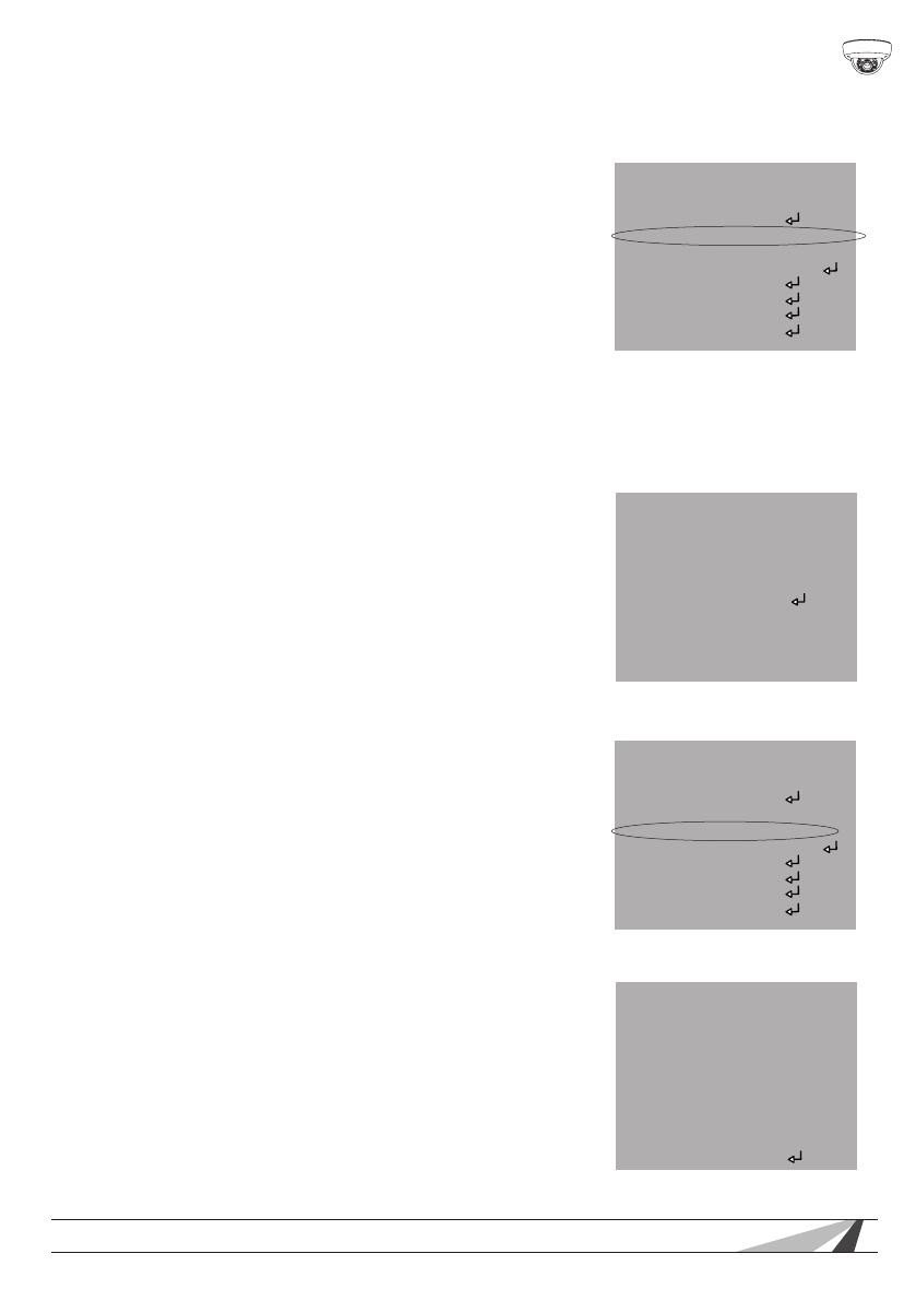
SETUP
LENS MANUAL
EXPOSURE
WHITE BAL. AWCSET
BACKLIGHT OFF
DAY&NIGHT AUTO
DPC
SPECIAL
RESET
EXIT
SETUP
LENS MANUAL
EXPOSURE
WHITE BAL. AWCSET
BACKLIGHT OFF
DAY&NIGHT AUTO
DPC
SPECIAL
RESET
EXIT
WB MANUAL
COLOR TEMP WHITE BAL
BLUE -----
RED -----
RETURN RET
BLC
AREA SEL. AREA1
AREA STATE ON
GAIN -----|--------106
HEIGHT ---------|----010
WIDTH ---|----------003
LEFT/RIGHT ------|-------006
TOP/BOTTOM -----|--------005
RETURN RET


