Page is loading ...

Owner'sManual
®
LiquidPropaneGasGrill
Model 141.15225
/_ WARNING:
Read this Owner's Manual carefully and be sure
your gas grill is properly assembled, installed and
maintained. Failure to follow these instructions
could result in serious bodily injury and!or property
damage. This gas grill is intended for outdoor use
only and is not intended to be installed in or on
recreational vehicles or boats.
Note to Installer: Leave this Owner's Manual
with consumer after delivery and/or installation.
Note to Consumer: Leave this Owner's Manual
in a convenient place for future reference.
Sears, Roebuck and Co.,
Hoffman Estates, IL 60179 U.S.A.
P80136003A - Date 2003/08/05

Warranty ..................................................... 2
Safety Instructions ...................................... 2
Hardware, Parts Diagram and Lists ..... 5
Assembly Instructions ................................. 9
Lighting Instructions .................................. 14
Cleaning and Maintenance Instructions .... 16
Frequently Asked Questions .................. 18
Cooking Instructions ................................ 19
Cooking Guide and Recipes ................ 20
Full 1-Year Warranty on Grill
For one year from the date of purchase Sears will
repair or replace, at our option, any grill part
(except for paint loss, rusting and ignitor battery)
that is defective in material or workmanship.
Limited Warranty on Selected Grill Parts
From one year after the date of purchase for the
designated time periods listed below, Sears will
replace the following gdll parts if they are defective
in material or workmanship. You will be charged for
labor.
• Lifetime of Grill: Aluminum Castings (except for paint
loss)
• 1 Year: Cast Iron Burners
• 2 Years: All Other Grill Parts (except flame tamers,
cooking grids and ignitor battery)
Warranty Service
Warranty service is available by contacting the ®
nearest Sears Service Center at 1-800-4-MY-HOME
Warranty Restrictions
• This warranty is void if grill is used for com-
mercial or rental purposes.
• This grill is for use with Liquid Propane (LP)
gas only. Any attempt to convert this gdll to
natural gas is dangerous and wilt void your
product warranty.
• This warranty applies only when the grill is
used in the United States.
• This warranty gives you specific legal rights,
and you may also have other rights which vary
from state to state.
Sears, Roebuck and Co., Dept. 817WA,
Hoffman Estates, IL 60179
Z_WARNING
Combustion byproducts produced when using
this product contain chemicals known to the
State of California to cause cancer, birth
defects, or other reproductive harm.
/_WARNING
Failure to comply with these instructions
could result in a fire or explosion that
could cause serious bodily injury, death, or
property damage.
Z_WARNING
Your grill will get very hot. Never lean over
the cooking area while using your gdll. Do not
touch cooking surfaces, grill housing, Lid or any
other grill parts while the gdll is in operation, or
until the grill has cooled clown after use.
Failure to comply with these instructions
may result in serious bodily injury.
FOR YOUR SAFETY
1. Do not store or use gasoline or other flam-
mable material and liquids in the vicinity of this
or any other appliance.
2. ALP cylinder not connected for use must not
be stored in the vicinity of this or any other
appliance.
FOR YOUR SAFETY
If you smell gas:
1. Shut off gas to the appliance.
2. Extinguish any open flame.
3. Open Lid.
4. If odor continues, immediately call your gas
supplier or your fire department.
IMPORTANT: Your Kenmore LP Gas Grill cannot
be converted to use Natural Gas. Attempting to do
so is extremely hazardous and will also void the
grill warranty.
Grill Installation Codes
This gas grill must be installed in accordance with
all local codes. In areas without local codes, follow
the latest edition of the National Fuel Gas Code
ANSI Z223.1. and National Electdcal Code ANSI/
NFPA 70 In Canada, installation must conform to
standard CAN/CGA lb149.1 or 1-b149.2 (Installation
Code for Gas Burning Appliances and Equipment)
and all local codes.
Correct LP Gas Tank Use
LP gas gdll models are designed for use with a
standard 20 lb. Liquid Propane Gas (LP gas) tank,
not included with grill box. Never connect your gas
grill to an LP gas tank that exceeds this capacity.
A tank of approximately 12 inches in diameter by
© Sears, Roebuck and Co.

18-1/2 inches high is the maximum size LP gas
tank to use. You must use an "OPD" gas tank
which offers an Overfill Prevention Device. This
safety feature prevents the tank from being overfilled
which can cause malfunction of the LP gas tank,
regulator and/or grill.
The LP gas tank must be constructed and marked
in accordance with specifications of the U.S. Dept.
of Transportation (DOT). In Canada, the LP gas
tank must meet the Canadian Transportation and
Communications (CTC) specifications. Also be sure
to read and follow all LP instructions below.
1. The LP gas tank has a shutoff valve,
terminating in an LP gas supply tank valve
outlet, that is compatible with a Type 1 tank
connection device. The LP gas tank must
also have a safety relief device that has a
direct communication with the vapor space of
the tank.
2. The tank supply system must be arranged
for vapor withdrawal.
3. The LP gas tank used must have a collar
to protect the tank valve.
Proper Placement and Clearance of Grill
Never use your gas grill in a garage, porch, shed,
breezeway or any other enclosed area. Your gas grill
isto be used outdoors only, at least 24 inches from
the back and side of any combustible surface.
Your gas gdll should net be placed under any
surface that will burn. Do net obstruct the flow of
ventilation air around the gas grill housing.
This outdoor gas grill isnot intended to be installed in
or on recreational vehicles and/or boats.
• Never connect an unregulated LP gas tank to
your gas grill. The gas regulator assembly
supplied with your gas gdll is adjusted to have
an outlet pressure of 11" water column (W.C.)
for connection to an LP gas tank.
• Only use the regulator and hose assembly
supplied with your gas grill. Replacement
regulators and hose assemblies must be those
specified by Sears.
• Have your LP gas tank filled by a reputable
propane gas dealer and visually inspected and
re-qualified at each filling.
• Never fill the gas tank beyond 80% full.
Have your propane gas dealer check the
release valve after every filling to ensure that
it remains free of defects.
• Always keep LP gas tanks in an upright
position.
• Do not store (or use) gasoline or other flammable
vapors and liquids in the vicinity of this gas grill.
• An LP gas tank that is not connected for use must
NOT be stored on bottom shelf or in the vicinity of
this or any other gas gdll.
• Do not subject the LP gas tank to excessive heat.
• Never store an LP gas tank indoors. If you
store your gas gdll in the garage or other indoor
location, always disconnect the LP gas tank
first and store it safely outside.
3
• LP gas tanks must be stored outdoors in a
well-ventilated area and out of the reach of
children. Disconnected LP gas tanks must not
be stored in a building, garage or any other
enclosed area.
• When your gas gdll is not in use the gas
must be turned off at the LP gas tank.
• The regulator and hose assembly must be
inspected before each use of the grill. If there
is excessive abrasion or wear or if the hose
is cut, it must be replaced prior to the grill
being used again.
• Keep the gas regulator hose away from hot
grill surfaces and dripping grease. Avoid
unnecessary twisting of hose. Visually inspect
hose prior to each use for cuts, cracks,
excessive wear or other damage. If the hose
appears damaged do not use the gas gdll.
Call Sears at 1-800-366-PART (1-800-366-
7278) for a Sears authodzed replacement
hose.
• Never light your gas grill with the lid closed
or before checking to insure the burner tubes
are fully seated over the gas valve odfices.
• Never allow children to operate your grill. Do
not allow children to play near your grill.
Z WARNING
A strong gas smell, or the hissing sound of
gas indicates a serious problem with your
gas gdll or the LP gas tank. Failure to
immediately follow the steps listed below
could result in a fire or explosion that could
cause sedous bodily injury, death, or
property damage.
Shut off gas supply to the gas gdll.
Turn the Control Knobs to OFF position.
Put out any flame with a fire extinguisher.
Open Grill Lid.
Get away from the LP gas tank.
Do not try to fix the problem yourself.
If odor continues or you have a fire you
cannot extinguish, call your fire department.
Do not call near the LP gas tank because
your telephone is an electdcal device and
could create a spark resulting in fire and/or
explosion.
NOTE: The normal flow of gas through the
regulator and hose assembly can create a
humming noise. A low volume of noise is
perfectly normal and wilt not interfere with
operation of the grill. If humming noise is
loud and excessive you may need to purge
air from the gas line or reset the regulator
excess gas flow device. This purging proce-
dure should be done every time a new LP
gas tank is connected to your grill. For help
with this procedure refer to page 15, step 4,
or call the Customer Service Helpline for
assistance, 8am - 8pm CST, Monday through
Friday 1-888-317-7642.

CAUTION:Spidersandsmallinsectsocca-
sionallyspinwebsor makenestsin the grill
BurnerTubesduringtransitandwarehousing.
Thesewebscanleadto a gasflowobstruc-
tion whichcouldresultina fire in andaround
the BurnerTubes.Thistypeof fire is known
as a "FLASHBACK"and cancauseserious
damageto yourgrillandcreateanunsafe
operatingconditionfor theuser.
To reducethechanceof "FLASHBACK",you
mustcleanthebumertubesbeforeassem-
blingyourgrill, andat leastoncea monthin
latesummeror earlyfall whenspidersare
mostactive.AlsoperformthisBurnerTube
cleaningprocedureif yourgrillhasnotbeen
usedfor an extendedperiodof time.
To reducethe chanceof "FLASHBACK"(see
CAUTIONat left)cleantheBurnerTubesand
Burnersbeforefullyassemblingyourgrill.
RemovetheCotterPinfromtherearunderside
of eachBurnerusinga pairof longnosepliers.
Carefullylift eachBurnerup andawayfromthe
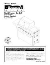
GasValveOrifice,thenreferto Figure1 and
performoneof thesethreecleaningmethods:
.
Bend a stiff wire, (a lightweight coat hanger
works well) into a small hook as shown
below. Run the hook through the Burner Tube
and inside the Burner several times to remove
any debris.
. Use a bottle brush with a flexible handle.
Run the brush through the Burner Tube and
inside the Burner several times, removing any
debris.
.
Use an air hose to force air through each
Bumer Tube. The forced air should pass
debris or obstructions through the Burner and
out the Ports.
Figure 1
GAS COLLECTOR BOX
SPARKELECTROOE BURNER BURNERPORT
TO CLEAN BURNER TUBE, ASSEMBLY _ / /_
INSERT HOOK HERE
BURNER TUBE
Long nose pliers can be used to remove
Cotter Pin when cleaning the Burners
Use work gloves to protect your hands
Wear eye protection
When you have finished assembling your
grill we strongly urge that all Pattern
Head Thumb Screws be tightened, either
with the supplied Tightening Tool or a
#2 Phillips Head Screwdriver
Tightening Tool
Ref, # P05515102K
Z WARNING
The location of the Burner Tube with re-
spect to the Orifice is vital for safe opera-
tion. Check to ensure the Orifice is inside
the Burner Tube before using your gas grill.
See Fig. 2. If the Burner Tube does not fit
over the Valve Orifice, lighting the Burner
may cause explosion and/or fire.
Figure 2
GAS VALVE ASSEMBLY
ORIFICE BURNER TUBE
4

The following table illustrates a breakdown of the hardware pack. It highlights what components are used
in the various stages of assembly.
Ref.
H017
H019
H017
H024
H020
H018
H017
P05301001A
Component Qty. to Use
1/4"xl/2" Pattern Head Screw 4
1/4"x2" Pattern Head Screw 8
1/4"xl/2" Pattern Head Screw 2
1/4"xl/2" Special Round Head Screw 2
1/4" Wing Nut 2
1/4"x3/4" Pattern Head Screw 8
1/4"xl/2" Pattern Head Screw
AA Battery
4
1
Purpose of Components
Attaches Foldable Cart Legs
Attaches Cart Legs To Bottom Shelf
Attaches Tank Holder To Bottom Shelf
Attaches Tank Hook To Grill Head
Attaches Tank Hook To Grill Head
Attaches Side Shelf and Side Burner To
Grill Head
Attaches Spice Basket To Side Shelf
Powers The Electric Ignitor
Actual Size and Quantity of Each Hardware Piece:
1/4"x2" Pattern Head Screw
Qty, 8
Re[ # H019
1/4"x3/4" Pattern Head Screw
Qty. 8
Ref. # H018
1/4"xl/2" Pattern Head Screw
Qty. 10
Ref. # H017
1/4"xl/2" Special Round Head
Screw
Qty. 2
Ref. # H024
1/4" Wing Nut
Qty. 2
Ref. # H020
AA Battery
Qty. 1
Ref. # P05301001A

The following table illustrates a breakdown of the hardware pack. It highlights what components are used
in the various stages of assembly.
Ref. Component Qty. to Use
P05515096LNo.14 Customized Wrench 1
P05313023BLighting Stick 1
H025 M4x8mm Pattern Head Screw 1
P05515102KTightening Tool 1
Purpose of Components
Tighten Caster
Attaches To Bowl Support Bracket - Left
Attaches To Bowl Support Bracket - Left
Allows you to tighten Pattern Head Thumb Screws
as needed
Actual Size and Quantity of Each Hardware Piece:
/
No.14 Customized Wrench
Qty, 1
Ref. # PO5515096L
Scale 1:0.6
)
/
J
J
Tightening Tool
Qty. 1
Ref. # PO5515102K
M4xSmm Pattern Head Screw
Qty. 1
Ref. # H025
Lighting Stick
Qty. 1 Ref. # PO5313023B
Ref. Component Qty. to Use
P03412331CControl Knob 1
P05501010BCotter Pin 1
H025 M4x8mm Pattern Head Screw 2
H027 M4 Plain Washer 2
Purpose of Components
Install To Side Burner Valve Stem
Secure To Side burner
Attaches To Side Burner Valve Bracket
Attaches To Side Burner Valve Bracket
Actual Size and Quantity of Each Hardware Piece:
/
I
\
M4x8mm Pattern Head Screw M4 Plain Washer
Qty. 2 Qty. 2
Ref. # H025 Ref. # H027
Control Knob Cotter Pin
Qty. 1 Qty. 1
Ref. # P03412331C Ref. # PO5501010B
6

10
1
22
17
21
40\
44 _ __,,_
33a_
46_\
4b
7

REF# DESCRIPTION
1, Lid - Porcelain
2, Lid Side Panel - Left
3, Lid Side Panel - Right
4, Temperature Gauge
5, Lid Handle / Round
6, Heat-Insulating Spacer
7, Name Plate
8a. Third Cooking Rack
8b. Secondary Cooking Rack
9, Cooking Grid
10. Flame Tamer
11. MainBurnerw. Heat-lnsulatingRing
12. Burner Bracket
13. Gas Collector Box & Electrode
14. Ignition Wire Set
15. Electric Ignitor
15a. AA Battery
16. Bowl Side Panel - Left
17. Bowl Side Panel - Right
18. Bowl Front Panel
19. Bowl Rear Panel
20. Grease Draining Tray
21. Grease Receptacle
22. Gas Valve/Manifold Assembly
23. Control Panel
24. Control Knob
25. Side Shelf - Left
26. Side Burner Frame
27. Spice Basket
28. Bottom Shelf
29. Bowl Support Bracket - Left
30. Bowl Support Bracket - Right
31. Cart Leg - Right
32. Cart Leg - Left
PART# QTY
PO0120054B 1
PO0105017K 1
PO0106017K 1
P00601174A 1
P00205002B 1
P06801001A 2
P00410037C 1
PO1504008E 1
PO1504017E 1
PO1602022E 2
PO1705024E 2
P02001048C 3
PO2203011B 1
P02608041C 2
P02615058A 1
P02502154C 1
P05301001A 1
P00720241A 1
P00721241A 1
P00738241A 1
P00725241A 1
P02705182B 1
P02701075B 1
Y0060093 1
P02906102B 1
P03412331C 4
P01102001C 1
P01104001C 1
P05204001C 2
PO1002002D 1
PO1304001D 1
PO1305001D 1
P00909002C 2
P00908003C 2
REF# DESCRIPTION PART# QTY
33. Caster PO5107001A 4
33a. No.14 Customzied Wrench PO5515096L 1
34. Caster Seat PO4509001A 4
35. Tank Hook P04001027C 1
36. Tank Holder P04002028C 1
37. Side Burner Lid P00115058K 1
38. Pot Support P00805013B 1
39. Side Burner Electrode PO2607042J 1
40. Side Burner P02002041C 1
41. Gas Valve for Side Burner P03218043A 1
42. Connection Tube P03702025A 1
43. Regulator with Hose P03601034A 1
44. Lighting Stick P05313023B 1
45. Heat Shield for Grease Tray P02711182B 1
46. Tightening Tool PO5515102K 1
--- Owner's Manual P80136003A 1
--- Hardware Pack P06001016A 1
--- Hardware Pack A P06011001A 1
--- Hardware Pack B PO6010001A 1
For the repair or replacement parts you need: Call
anytime
1-800-4-MY-HeM E®(1-800-469-4663)
To make sure you obtain the correct replacement
parts for your Kenmore gas grill, please refer to
the part numbers in this parts list. The following
information is required to assure you receive the
correct parts:
1. Grill Model Number (see CSA label on grill)
2. Part Number
3. Part Description
4. Quantity of parts needed
Important: Keep this Owner's Manual for convenient
referral and for part replacement.
Important: Use only Sears authorized parts. The
use of any part that is not Sears authorized can
be dangerous and will also void your product
warranty.
8

CAUTION: While it is possible for one person to as-
semble this grill, obtain assistance from another person
when handling some of the larger, heavier pieces,
especially the grill head.
1. Open Lid of shipping carton and remove top sheet of
cardboard. Lay cardboard sheet on floor and use as
a work surface to protect floor and gdll parts from
scratches.
2. Remove packing materials and cart parts from
shipping carton.
3. You may slice the carton front corners with a utility
knife to lay open the carton front panel. This will
allow you to raise the grill head Lid and remove the
components packed inside the head, making it
easier to lift.
4. With an assistant, lift the gdll head out of the ship-
ping carton and place it on the cardboard work sur-
face. See Fig. 1.
5. Use the parts list to check that all parts have been
included.
6. Inspect the grill for damage as you assemble it. Do
not assemble or operate the grill if it appears
damaged. If there are damaged or missing parts
when you unpack the shipping box, or you have
questions during the assembly process, call:
1-888-317-7642
8 a.m. - 8 p.m CST, Mon. - Fri.
Figure 2
CART LEG-RIGHT
Figure 3
BOTTOM SHELF
HOLES FOR TANK_
HOLDER
CART LEG-LEFT
GRILL HEAD
CART LEG-LEFT
Assembling The Cart To The Grill Head
1. Lay the Grill Head flat on its back as shown in
Fig. 2. Unfold the 4 pre-assembled Cart Legs
as shown in Fig. 2. Tighten securely using 4 of
the 1/4"xl/2" Pattern Head Screws provided.
2. Before attaching the Bottom Shelf to the Cart
Legs be sure the holes for the Tank Holder on
Bottom Shelf are located on the dght.
3. Install the Bottom Shelf between the Cart Legs.
Align the holes on Cart Legs with the threaded
holes at the corners of Bottom Shelf. Tighten
securely using 8 of the 1/4"x2" Pattern Head
Screws provided. See Fig. 3.
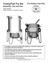
4. Screw the 4 Casters intothe Caster Seats (see bottom
of Cart Legs). Turn the threaded Caster Stem by hand,
clockwise until it stops. Tighten securely by using the
Customized Wrench provided. See Fig. 4.
Figure 1
_RILL HEAD
Figure 4
CART LEG-RIGHT
CASTER
BOTTOM SHELF
_.
GRILL HEAD
CART LEG-LEFT
CART LEG-RIGHT
GRILL HEAD
9

.
Be sure all 4 Casters are locked, then with
the assistance of another person, turn the
assembled gdll upright. See Fig 5. Install Tank
Holder to nght side of Bottom Shelf. Align the
holes on Tank Holder with the threaded holes on
the side of Bottom Shelf. Tighten securely
using 2 of the 1/4"xl/2" Pattern Head Screws
provided.
6.
Attach the Tank Hook to the right side of Grill
Head as shown in Fig. 5. Align holes of Tank
Hook with holes on the right side of Gdll Head.
Secure firmly using 2 of the 1/4"xl/2" Special
Round Head Screws and 2 of the 1/4" Wing Nuts
provided. Insert screws from inside Grill Head and
attach Wing Nuts from outside of Tank Hook.
7. Position Heat Shield into slots in Grease
Draining Tray.
.
From the back side of Grill Head install the
Grease Draining Tray and Heat Shield. See
Fig. 5. The Heat Shield is required to be
present and centered for your safety.
9. Install the Grease Receptacle under Grease
Draining Tray. See Fig. 5.
Installing Manual Lighting Stick
1. Attach the Manual Lighting Stick to the Left
Bowl Support Bracket as shown in Fig. 5a.
Align the hole at the end of Manual Lighting
Stick Wire with the threaded hole on the Left
Bowl Support Bracket. Tighten securely using
the M4x8mm Pattern Head Screw packed with
the Manual Lighting Stick.
Figure 5a
Figure 5
GRILL HEAD
Figure 6
BOWL SUPPORT
BRACKET-LEFT
GREASE
RECEPTACLE
HEAT SHtELD
TANK HOLDER
SIDE SHELF FRAME
/
GRILL HEAD
Z
GREASE
DRAINING
TRAY
SIDE BURNER
FRAME
M4xSmm PATTERN
HEAD SCREW__
BOWLSUPPORT
BRACKET-LEFT
Installing Side Shelf and Side Burner
Remove Side Burner from Side Burner Kit before
installing.
1.
Enlisting the aid of an assistant, attach Side Burner
Frame to right side of grill Attach Side Shelf
Frame to left side of grill as shown in Fig. 6.
Be sure the holes for the Spice Baskets appear
on the front side of the grill. Align the 4 holes
on Side Shelf Frame and Side Burner Frame
with the threaded holes on left and right Bowl
Support Brackets. Tighten securely using 4 of
the 1/4"x3/4" Pattern Head Screws provided.
BOWL SUPPORT
BRACKET-RIGHT
Figure 6a
M4x8mm PATTERN
HEAD SCREW
AND WASHER
HOLES FOR SIDE
BURNER VALVE KiT
SIDE BURNER
FRAME
;EMBLED
VALVE KIT
BURNER
VALVE BRACKET
2. Install the Pre-assembled Valve Kit to the Side
Bumer Frame. See Fig. 6a.
10

AttachthePre-assembledValveKitto the Side
BumerValveHoleon theSideBurnerFrame
as shownin Fig. 6a.(on page10) Alignthe
2 holeson the Side BurnerFramewith the
threadedholesontheSideBurnerValveBracket.
Tightensecurelyusing2ofM4x8mmPatternHead
Screwsand2 Washerspacked with the Control
Knob.
Figure 6b
POT
SUPPORT
SIDE
.
4.
5.
Cut Fastening Band from Pot Support and set Pot
Support aside. Install the Side Burner through the
top hole in Side Burner Frame and onto the Side
Burner Valve. Make sure that opening at end of
Side Burner Tube goes over tip of Side Burner
Valve. Secure Side Burner with supplied Cotter
Pin (packed in Side Burner Control Knob bag)
See Fig. 6b. Place Pot Support into position on
Side Burner Frame.
Install the Control Knob to the Side Burner Valve
Stem. See Fig. 6b.
Connect the Ignition Wire terminal from Side Burner
with the other from Grill Head. See Fig. 6b. Bind
the connected Ignition Wires and Connection Tube
together using the supplied Fastening Band.
CONTROL
KNO_
FASTENING
BAND
COTTER
PIN
BURNER
FRAME
VALVE KIT
FROM SIDE BURNER
_NiTION WIRE
FROM GRILL HEAD
6. The gap between the Side Burner Electrode Tip and
the Side Burner Port should be approximately
1/8"-3/16". See Fig. 6c.
7. If the gap is wider than 3/16", use a pair of long
nose pliers and gently bend the Electrode Tip
toward the burner.
8. Place the Pot Support into the Side Bumer Frame.
See Fig. 6b.
Installing Spice Basket
1.
Attach a Spice Basket onto the front of the
Side Shelf and the Bowl Support Bracket as
shown in Fig. 7. Tighten securely using 2 of
the 1/4"xl/2" Pattern Head Screws provided.
Repeat this step to attach the Spice Basket
onto the front of Side Burner.
When you have finished assembling your
grill we strongly urge that all Pattern
Head Thumb Screws be tightened, either
with the supplied Tightening Tool or a
#2 Phillips Head Screwdriver
Tightening Tool
Ref. # P05515102K
Figure 6c
I/8"-3/16" BURNER
BURNBR
Figure 7
SIDE SHELF
GRILL HEAD
BOWL SUPPORT
SPICE
BASKET
BOWL SUPPORT
BRACKET-LEFT
SIDE BURNER
KIT
SPICE BASKET
11

Ignitor Battery Installation - See Fig. 8
1. Unscrew the Ignitor Cap located on the grill
Control Panel and remove the Contact and
Spring from the Ignitor Slot.
2. Place the manufacturer supplied AA battery
into the Ignitor Slot. Be sure to place the
positive pole facing toward you. See Fig. 8.
3. Place the Spring over the AA battery, then
place the Contact on top of the Spring.
Screw the Ignitor Cap back onto the grill
Control Panel.
4. Remove any protective film from outside and
inside of Grill Head.
.
If no "clicking" sound is heard check the
following common causes. If you need assis-
tance call our Customer Service Helpline
at 1-888-317-7642.
Ignitor AA battery not installed properly.
Ignitor wires may be loose. Remove the AA battery,
inspect the Ignitor Junction Box found behind the
Control Panel, and connect any loose wires.
Figure 8
Electrode Check - Requires an Assistant
Before placing the cooking components into your
grill, ensure that the Spark Electrode Tip is prop-
eriy positioned within each Gas Collector Box (a
3-1/4" wide stainless mechanism found at the front
between each set of Burners.) The easiest way to
ensure this is to perform this Electrode Check:
1. Be sure all Control Knobs are set to "OFF"
and open the Grill Lid.
2. Have an assistant stand behind to the right of
the grill and look down at each Gas Collector
Box. NEVER put your face inside Grill Head.
3. Press the Ignitor Cap. You should hear a
"clicking" sound and your assistant should see
a small blue spark within each Gas Collector
Box. If a spark is present the Electrode Tips
are properly positioned.
4. If no spark is seen the Spark Gap shown in
Fig. 9 needs to be adjusted as follows:
Using an adjustable wrench, loosen the Inside Nut
just until the Gas Collector Box can be maneuvered
and turned upward.
The gap between the Spark Electrode Tip and
Spark receiver should be approximately 3/16".
If the gap is wider than 3/16" use a pair of long
nose pliers and gently squeeze the Gas Collector
Box until the gap is correct.
Return the Gas Collector Box to its original horizon-
tal position, secure the Inside Nut and try the
Electrode Check again.
AA BATTERY
IGNITOR CAP "_'f
SPRING
CONTACT
Figure 9 - Side View Figure
GAS COLLECTOR BOX
SPARK RECEIVER
SLOT
12

Installing Cooking Components
Important: Before cooking on your grill the first
time, wash the Cooking Grids and Cooking Racks
with warm, soapy water. Rinse and dry thoroughly.
Season with cooking oil regularly. After cooking is
completed, turn gdll to HIGH setting for about five
minutes to burn off excess grease or food residue.
1. Place the 2 Flame Tamers on the lower ledge
above Burners. See Fig. 10.
2. Evenly space the Cooking Grids on the ledge
above the Flame Tamers.
Figure 10
THIRD COOKING RACK
SECONDARY
RACK
COOKING
RACK
3. Place the Secondary Cooking Rack into the
slots on the upper left and upper right of Grill
Bowl Side Panels. See Fig. 10.
4. Place Third Cooking Rack on top of the
Secondary Cooking Rack. See Fig. 10.
Connecting A Liquid Propane Gas (LP gas)
Tank To Your Grill
1.
Hang your filled gas tank on the top Tank
Hook. The ring foot of the gas tank will rest
on the Tank Holder. See Fig. 11. Make sure
the LP gas tank valve is in the full OFF
position. (Turn clockwise to close.)
2. Check the tank valve to insure it has proper
external mating threads to fit the hose &
regulator assembly provided. (Type 1 connec-
tion per ANSI Z21.58a-1998)
.
4.
Make sure all Burner Valves are in the OFF
position.
Inspect the valve connection port and regulator
assembly. Look for damage or debris. Remove
any debds. Inspect hose for damage. Never
use damaged or plugged equipment.
5. When connecting the hose and regulator
assembly to the tank valve, hand tighten nut
clockwise to a full stop. DO NOT use a
wrench to tighten because it could damage
the Quick Coupling Nut and result in a
hazardous condition. See Fig.12.
6. Open the tank valve fully (counterclockwise).
Use a soapy water solution to check all
connections for leaks before attempting to light
your grill. See "Checking for LP Gas Leaks"
on page 14. If a leak is found, turn the tank
valve off and do not use your grill until the
leak is repaired.
Disconnecting A Liquid Propane Gas (LP gas)
Tank From Your Grill
1.
2.
Turn the Burner Valves and LP gas tank
valve to the full OFF position. (Turn clockwise
to close.)
Detach the hose and regulator assembly from
the LP gas tank valve by turning the Quick
Coupling Nut counterclockwise.
Figure 11
LP GAS TANK
TANK HOLDER
Figure 12
SiDE
BURNER
ALREADY _ KIT
CONNECTED
COUPLING
NUT
CAUTION: When the appliance is not in use, the
gas must be turned off at the supply tank.
Congratulations
Your Kenmore LP gas grill is now ready for
use. Before the first use and at the begin-
ning of each season (and whenever the LP
gas tank has been changed):
1. Read all safety, lighting and operating
instructions.
2. Check Gas Valve Orifices, Burner Tubes
and Burner Ports for any obstructions.
3. Perform gas leak check according to
instructions found on page 14 of this
manual.
13

/ XWARNING
A strong gas smell, or the hissing sound of
gas indicates a serious problem with your
gas grill or the LP gas tank. Failure to
immediately follow the steps listed below
could result in a fire or explosion that could
cause serious bodily injury, death, or
property damage.
• Shut off gas supply to the gas grill.
• Turn the Control Knobs to OFF position.
• Put out any flame with a fire extinguisher.
• Open Grill Lid.
• Get away from the LP gas tank.
• Do not try to fix the problem yourself.
• If odor continues or you have a fire you
cannot extinguish, call your fire department.
Do not calt near the LP gas tank because
your telephone is an electrical device and
could create a spark resulting in fire and/or
explosion.
NOTE: The normal flow of gas through the
regulator and hose assembly can create a
humming noise. A low volume of noise is
perfectly normal and will not interfere with
operation of the grill. If humming noise is
loud and excessive you may need to purge
air from the gas line or reset the regulator
excess gas flow device. This purging proce-
dure should be done every time a new LP
gas tank is connected to your grill. For help
with this procedure refer to page 15, step 4,
or catl the Customer Service Helpline for
assistance.
Basic Lighting Procedures
1. Familiarize yourself with the safety guidelines at
the front ofthis manual. Do not smoke while
lighting grill or checking gas supply connections.
2. Be sure the LP gas tank is filled.
3. Check that the end of each Burner Tube is
properly located over each Valve Orifice.
4. Make sure alt gas connections are securely
tightened.
5. Open the Grill Lid or Side Burner Lid, depending
on the burner you are lighting.
Z WARNING
Failure to open Grill Lid during the
lighting procedures could result in a fire
or explosion that could cause serious
bodily injury, death, or property damage.
,
Set Control Knobs to OFF and open the LP gas
tank valve slowly until 1/4 to 1/2 open.
Open LP
gas tank
OFF
J
_J
7. Push and turn the LEFT Control Knob to HIGH.
Checking For LP Gas Leaks
Never test for leaks with a flame. Prior to first
use, at the beginning of each season, or every
time your LP gas tank is changed, you must
check for gas leaks. Follow these four steps:
1. Make a soap solution by mixing one part
liquid detergent and one part water.
2. Turn the grill Control Knobs to the full OFF
position, then turn the gas ON at source.
3. Apply the soap solution to all gas connec-
tions. If bubbles appear in the soap solution
the connections are not properly sealed.
Check each fitting and tighten or repair as
necessary.
4. If you have a gas leak that you cannot
repair, turn off the gas at the source, discon-
nect fuel line from your grill and call
1-800-4-MY-HOME ® or your gas supplier for
repair assistance.
HIGH
OFF
8. Immediately press the Electric ignitor for 3-4
seconds to light the Burner.
PRESS
14
9. If the burner does not light, turn the Control Knob
to OFF, wait 5 minutes for gas to clear, then retry.
10. Once the left grill burner is ignited, the adjacent
burner can be lit by simply turning its Control Knob
toHIGH.
11. Adjust Control Knobs to your desired cooking
temperature.

Manually Lighting Your Grill by Match
To light your gas grill by match, insert a match into the
Manual Lighting Stick and follow steps 1through 6 of
the Basic Lighting Procedures. Then, light the match
and place Manual Lighting Stick through the Lighting
Hole on the left side of the gdll. See Fig. 13. Turn the
nearest Control Knob to the HIGH setting to release
gas. The Bumer should liaht immediatelv.
Figure 13
• Misalignment of Ignitor on Burner
Correction: Check for proper position of the
Electrode Tip as shown in Figures 6c and 9.
The gap between the Spark Electrode Tip and
Burner or Spark Receiver should be approxi-
mately 3/16". Adjust if necessary. With the gas
supply closed and all Control Knobs set to OFF
press the Electric Ignitor Cap and check for the
presence of a spark at the Electrode.
• Disconnected Ignition Wires
Correction: Inspect the Ignitor Junction Box
found behind the Control Panel. Connect loose
Ignitor wires to Junction Box and try to light the
grill.
HOLE
LIGHTING
STICK
MATCH
Z WARNING
Never lean over the grill cooking area while
lighting your gas grill. Keep your face and
body a safe distance (at least 18 inches)
from the Lighting Hole or Burners, when
lighting your grill by match.
If the grill fails to light :
1. Turn gas off at source and turn the Control Knob
to OFF. Wait at least five minutes for gas to clear,
then retry.
2. If your grill still fails to light, check gas supply
and connections.
3. Repeat lighting procedure. If your grill still fails
to operate, turn the gas off at source, turn the
Control Knobs to OFF, then check the following:
• Misatignment of Bumer Tubes over Orifices
Correction: Reposition BumerTubes over Ori-
rices.
• Obstruction ingas line
Correction: Remove fuel line from grill. Do not
smoker Open gas supply for one second to clear
any obstruction from fuel line. Close off gas supply
at source and reconnect fuel line to grill.
• Plugged Odfice
Correction: Remove Burners from gdll by pulling
Cotter Pin (beneath burner) using Long nose
pliers. Carefully lift each Burner up and away
from Gas Valve Orifice. Remove the Orifice from
gas valve and gently clear any obstruction with a
fine wire. Then reinstall all Orifices, Burners,
Cotter Pins and cooking components.
If an obstruction issuspected in gas valves or
gas valve bracket, please call for repair service at
1-800-4-MY-HOME. @
• Obstruction in Burner Tubes
Correction: Follow the Burner Tube cleaning
procedure on page 17 of this Owner's Manual.
4.
.
15
• Weak AA battery
Correction: Unscrew the Ignitor Cap and
replace the battery.
If the grill still does not light you may need
to purge air from the gas line or reset the
regulator excess gas flow device. Note: This
procedure should be done every time a new
LP gas tank is connected to your gdll.
To purge air from your gas line and/or
reset the regulator excess gas flow device:
• Turn the Control Knobs to the OFF posi
tion.
• Turn off the gas at the tank valve.
• Disconnect regulator from LP gas tank.
• Let unit stand for 5 minutes.
• Reconnect regulator to the LP gas tank.
• Turn the tank valve on slowly until 1/4 to
1/2 open.
• Open the Grill Lid.
• Set Control Knobs to OFF
Push and turn the LEFT Control Knob to
HIGH.
If all checks or corrections have been made and
you still have questions about operating your gas
grill, call the Customer Service Helpline
8am - 8pm CST, Monday through Friday at
1-888-317-7642.
Z WARNING
Should a "FLASH-BACK" fire occur in/or
around the Burner Tubes, follow the
instructions below. Failure to comply with
these instructions could result in a fire or
explosion that could cause serious bodily
injury, death, or property damage.
• Shut off gas supply to the gas grill.
• Turn the Control Knobs to OFF position.
• Put out any flame with a proper fire
extinguisher.
• Open grill Lid.
• Once the grill has cooled down, clean the
Burner Tubes and Burners according to
the cleaning instructions found on page 17
in this manual.

Aswithallappliances,propercareandmaintenance
willkeepyourgrillintopoperatingconditionand
prolongitslife.Byfollowingthesecleaningprocedures
onatimelybasis,yourgrillwillstaycleanandwork
properlywithminimumeffort.
ImportantNote:Useaspongeorwashclothtoclean
exteriorgrillsurfaces.Afiberorbrasscleaningbrush
canbeusedtocleaninteriorgrillpartswhichwill
accumulatefoodandgrease;GrillBowl,Cooking
Grids,FlameTamers,GreaseDrainingTrayand
GreaseReceptacle.Neveruseawirebrushormetal
scraperwhichcanscratchorchiptheporcelainfinish
ofyourgrillandpromoterustingwhichisnotcovered
byyourproductwarranty.
Cleaning the Cooking Grids
Before initial use and as needed, wash Cooking Grids
with a mild detergent and rinse with hot water. For
stubborn food residue use a degreaser and fiber or
brass cleaning brush. Dry immediately using a soft
cloth or paper towels.
CAUTION: Never clean your grill unless you are
sure it is cool to the touch.
Cleaning the Flame Tamers
To reduce the chance of flare-ups, Flame Tamers
should be cleaned whenever food or grease drippings
accumulate. Wash Flame Tamers with a mild deter-
gent and rinse with hot water. Dry the Flame Tamers
thoroughly before you reinstall them into the grill bowl.
To remove stubborn food residue use a degreaser and
fiber or brass cleaning brush.
Cleaning the Grease Draining Tray, Heat Shield
and Grease Receptacle
To reduce the chance of fire, the Grease Draining Tray,
Heat Shield and Grease Receptacle should be in-
spected before each grill use. Remove grease
(a plastic spatula works well) and wash all parts with a
mild soap and warm water solution.
Cleaning Exterior Surfaces
Before initial use, and periodically thereafter, we
suggest you wash your grill using a mild soap and
warm water solution. You can use a wash cloth or
sponge for this process. Do not use a stiff wire or
brass brush that might remove paint during the clean-
ing process.
Keep outdoor cooking gas appliance area clear and
free from combustible materials, gasoline and other
flammable vapors and liquids.
Cleaning the Grill Interior
Burning-off the grill after every cookout will keep it
ready for instant use. However, once a year you should
give the entire grill a thorough cleaning to keep it in top
operating condition. Follow these steps:
1. Turn all Burner Valves to the full OFF position.
2. Turn the LP gas tank valve to the full OFF position.
3.
Disconnect the regulator from the gas tank. Inspect
the hose with regulator assembly for cracking cutor
anyotherdamage and replace as neccessarywith
Sears replacement part number found on the Parts
List.
4. Remove and clean the Flame Tamers, Cooking
Grids, Cooking Rack and Grill Burners.
5. Cover each Gas Valve Orifice with aluminum foil.
6.
Brush the inside and bottom of the grill with a fiber
or brass cleaning brush, and wash with a mild
soap and warm water solution. Rinse thoroughly
and let dry.
7. Remove aluminum foil from Orifices and check
each Orifice for obstruction.
8. Check each Spark Electrode, adjusting as needed.
The space between the Spark Electrode Tip and
Spark Receiver should be approximately 3/16".
9. Replace the Burners and adjust the Gas Collector
Box. The edge of the collector box should be
overlapping the Burner Port.
10. Replace Flame Tamers and the Cooking Grids.
11. Reconnect the gas source and observe the Burner
flame for correct operation.
16

Cleaning The Burner Tubes and Burner Ports
To reduce the chance of "FLASH-BACK" the proce-
dure below should be followed at least once a month in
late summer or early fall when spiders are most active
or when your grill has not been used for a period of
time.
1. Turn all Burner Valves to the fult OFF position.
2. Turn the LP gas tank valve to the full OFF position.
3. Detach the LP gas regulator assembly from your
gas grill.
4. Remove the Cooking Grids, Flame Tamers, and
Grease Trays from your grill.
5. Remove the Cotter Pin from the rear underside of
each burner using a pair of long nose pliers.
6. Carefully lift each burner up and away from the
Gas Valve Orifice.
7. Refer to Fig. 1 and perform one of these
three cleaning methods:
Bend a stiff wire, (a lightweight coat
hanger works well) into a small hook as
shown below. Run the hook through the
Burner Tube and inside the Burner several
times to remove any debris.
,)
Use a bottle brush with a flexible handle.
Run the brush through the Burner Tube
and inside the Burner several times,
removing any debris.
Use an air hose to force air through each
Burner Tube. The forced air should pass
debris or obstructions through the Burner
and out the Ports.
Regardless of which Burner cleaning procedure you
use, we recommend you also complete the following
steps to help prolong Burner life.
1. Use a fiber pad or nylon brush to clean the entire
outer surface of each Burner until free of food
residue and dirt.
2.
3.
Clean any clogged Ports with a stiff wire, such as
an open paper clip.
Inspect each Burner for damage (cracks or holes)
and if such damage is found, order and install a
new burner. After installation, check to insure that
the Gas Valve Orifices are correctly placed inside
the ends of the Burner Tubes. Also check the
position of your Spark Electrode.
/ WARNING
The location of the Burner Tube with respect
to the Orifice is vital for safe operation.
Check to ensure the Orifice is inside of the
Burner Tube before using your gas grill. See
Fig. 2. If the Burner Tube does not fit over
the Valve Orifice, lighting the Burner may
cause explosion and/or fire.
Figure 2
GASVALVEASSEMBLY
ORIFICE BURNER TUBE
Figure 1 GAS COLLECTOR BOX
BURNER BURNERPORT
FOOTcoTTER PIN
BURNER TUBE
17

Question: Can I convert my Kenmore gas grill from
one fuel type to another?
Answer: Your Kenmore gas grill is manufactured to
exact specifications and is approved by the Canadian
Standards Association (CSA) for LP gas use only. For
your own safety, conversion kits are not available and
any attempt to convert your grill from LP gas to Natural
Gas will void your product warranty.
Question: Are the serial and model numbers of my
grill listed somewhere for future reference?
Answer: Yes, this valuable information islisted on a
silver label found on the right side of your Gdll Head
under the Side Shelf.
Question: Why doesn't the hose and regulator assem-
bly supplied with my new Kenmore grill fit the older LP
gas tank I've used for years?
Answer: The U.S. Government regulates gas appli-
ances and LP gas tanks. Whenever new regulations are
passed the LP gas tank fittings are altered. If your
current tank does not fit the hose and regulator supplied
with your new gdli, the tank is outdated and must be
replaced.
Question: What can cause grill partsto rust and what
affect does it have on the grill materials.
Answer: Rusting is a natural oxidation process and may
appear on Cast-Iron Burners, Steel Cooking Grids,
Steel Flame Tamers and steel cart parts. Because your
gdll is manufactured with heavy gauge steel, rust will not
affect the short term performance of your grill or affect
the taste of your foods.
To protect against the natural rusting process, your
Cooking Gdds and Flame Tamers have a porcelain
finish. However, dropping, scraping or scratching these
items will damage the porcelain finish and allow rusting.
Tominimize rusting we recommend you "season" the
Cooking Grids regularl_efore and after each use.
Consistent seasoning will help cast-iron resist rusting
and will create a non-stick cooking surface.
Question: How do I season my Cooking Grids?
Answer: Before and after each cookout, apply a thin
layer of cooking oil, spray or vegetable shortening to
each Cooking Grid. Be sure to coat the entire surface
including edges and any areas with chipped porcelain.
Insert the Cooking Grids into your warm grill for 2 to 3
minutes.
Question: Sometimes my gdll does not light when I
push the Ignitor Button. Why?
Answer: Refer to the Lighting Instructions in this
Owner's Manual. Also check these common causes.
•Ignitor AA battery may need replacing.
•Ignitor wires may be loose. Remove the AA
battery, inspect the Ignitor Junction Box found
behind the Control Panel, and connect any loose
wires.
Question: What is the best way to protect my new
Kenmore gas gdll from the weather?
Answer: A good quality grill cover should be used to
protect your grill when not in use. Kenmore Grill Cover
#15831 is made to fit this particular grill model. Also,
follow the cleaning and maintenance instructions in this
Owner's Manual on a timely basis, and your new gdll will
give you years of enjoyment.
Question: Where can I buy replacement parts?
Answer: For the repair or replacement parts you
need call 6 am - 11 pm CST, 7 days a week 1-800-
366-PART (1-800-366-7278). Use only Sears autho-
rized parts. The use of any part that is not Sears
authorized can be dangerous and will also void your
product warranty.
Question: Sometimes I hear a humming sound
coming from my regulator. What causes this?
Answer: The humming noise is actually the gas
flowing through the regulator. A low volume of noise is
perfectly normal and will not interfere with the opera-
tions of the grill. If humming noise is loud and exces-
sive you may need to purge air from the gas line or
reset the regulator excess gas flow device. Note: This
purging procedure should be done every time a new
LP gas tank is connected to your grill. For help with
this procedure refer to page 15, step 4, or call the
Customer Service Helpline, 8am - 8pm CST,
Monday through Friday at
1-888-317-7642.
18

Z WARNING
Your grill will get very hot. Always wear a
flame retardant BBQ Mitt when cooking on your
gdll. Never lean over cooking areas while using
gdll. Do not touch cooking surfaces, Lid, gdll
housing or other parts while grill is in operation,
or until the grill has cooled down after use.
Failure to comply with these instructions
may result in serious bodily injury.
Bum-Off
Before cooking on your gas grill for the first time, you will
want to "bum off" the grill to eliminate any odor or
foreign matter. Just ignite the burners, lower the Lid, and
operate grill on the HIGH setting for three to five minutes.
CAUTION:
Operating your gdll on the HIGH setting for longer than
five minutes may damage certain parts of your grill. Do
not leave your grill unattended.
Indirect Cooking
The indirect cooking method can also be used with the
supplied Cooking Gdds. To cook indirectly, the food
should be placed on the left or dght side of your grill
with the Burner lit on the opposite side. Or place your
food on the Secondary Cooking Rack mounted inside
your gdll bowl and light the 2 outer grill Burners. Either
way, indirect cooking must be done with the Lid
down.
Seasoning Cooking Grids
Before and after each cookout, applya thin layer of
cooking oil, spray or vegetable shortening to each
Cooking Grid. Be sure to coat the entire surface includ-
ing edges and any areas with chipped porcelain.Insert
the Cooking Grids into your warm grill for 2 to 3 minutes.
Flare-Ups
The fats and juices dripping from grilled food can cause
flare-ups. Since flare-ups impart a favorably, distinctive
taste and color to food cooked over an open flame,
they should be accepted up to a point. Nevertheless,
uncontrolled flaring can result in a ruined meal.
Preheating
To preheat, light your gdll on HIGH, lower the Lid and
follow this timetable:
• For high temperature cooking, preheat gdll
3 to 5 minutes.
• For low temperature cooking, preheat griit
3 minutes.
• To slow cook, preheating is not necessary.
Cooking Temperatures
High setting: Only use this setting for fast warm-up,
seadng steaks or chops and for burning food residue
off the grill after cooking iscomplete. Never use the
HIGH setting for extended cooking.
Medium to Low Settings: Most recipes specify
medium to low settings, including all smoking, rotis-
serie cooking and for cooking lean cuts such as fish.
NOTE: Temperature settings will vary with the tem-
perature and the amount of wind outside your home.
Direct Cooking
Z WARNING
Do not line the bottom of the grill housing
with aluminum foil, sand or any substance
that will restdct the flow of grease into the
Grease Draining Tray and Receptacle.
Failure to comply with these instructions
could result in a fire or explosion which
could cause serious bodily injury, death, or
property damage.
CONGRATULATIONS
Your Kenmore gas grill is now ready to grill. Re-
member to keep the Lid up when cooking directly on
the grill. For most foods it's best to start grilling on
high. Once the food is seared, reduce the heat to
medium. Foods marinated with ingredients such as
honey may burn because of the high sugar content.
You should begin their cooking on medium.
Always follow safety procedures as outlined in this
manual and wear a flame retardant BBQ Mittwhen
cooking on your gdlL
The direct cooking method can be used with the
supplied Cooking Grids and food placed directly over
the lit grill Burners. Direct Cooking requires the Grill
Lid to be open. This method is ideal for many recipes
including deep frying, seadng and whenever you want
meat, poultry or fish to have an open-flame barbecued
taste.
19

Grilling Steak and Ribs
Turn the grill Burners on HIGH, close the Lid
and preheat your grill 3 to 5 minutes.Open
Lid and place the meat on the Cooking Grid
directly above the lit Burners. Cook the meat
on both sides until seared. Reduce the heat
to MEDIUM and cook meat until done. Grilling
times will vary according to meat thickness.
Grilling Hamburgers and Sausages
Turn the grill Burners on HIGH, close Lid and
preheat your grill 3 to 5 minutes. Open Lid
and place the meat on the Cooking Grid
directly above the lit Burners. Cook the meat
on both sides until seared. Reduce the heat
to MEDIUM and cook the meat until done.
Grilling times will vary according to meat
thickness.
Grilling Poultry
Turn the grill Burners on HIGH, close Lidand
preheat your grill 2 to 3 minutes. Then raise
the Lid, reduce heat to MEDIUM and cook
poultry directly over lit Burners until done.
Poultry skin is fatty so you should expect
some flare-ups when using this direct
method.
To minimize flare-ups, try grilling poultry using
the indirect method. Place the poultry on one
side of the grill with the opposing Burners on
MEDIUM heat, and lower the gdll Lid. Grilling
times will vary based on the size of your
poultry.
Grilling Pork
Turn Burners on HIGH and preheat your grill
3 to 5 minutes with the Lid closed. Raise Lid,
place pork on Cooking Grid and cook until
seared. Reduce heat to MEDIUM and cook
until done. Gdlling times wilt vary according to
meat thickness.
Cut of Meat
T-bone steak
Sirloin steak
Beef spare ribs
Porterhouse steak
New York strip steak
Hamburgers
Sausages
Chicken breast
(cook with bone down)
Chicken wings
Drumsticks
Whole bird
(cook with breast up)
Chops
Loins
Cutlets
Approximate Cooking Times
Rare: 4-8 minutes
Medium: 10-14 minutes
Well done: 15-20 minutes
Rare: 4-6 minutes
Medium: 8-10 minutes
Well done: 10-15 minutes
Direct method:
approximately 15 minutes
Indirect method:
up to 30 minutes
Indirect method:
approximately 1 hour
Medium: 10-14 minutes
Well done: 15-20 minutes
2O
/