JCM Technologies Wave Quick start guide
- Category
- Wall transmitters
- Type
- Quick start guide
This manual is also suitable for

1248003-GB_v1.1
1

1248003-GB_v1.1
2
TECHNICAL CHARACTERISTICS
WAVE500 WAVE500-B
Frequency 868,35MHz 868,35MHz
Coding High security rolling code High security rolling code
Memory 500 codes 500 codes
Number of relays 1/2 relays (expandable up to 4) 1/2 relays (expandable up to 4)
Supply 230V ac 12/24V ac/dc
Power supply range +/- 10%
9-23 / 22-35V dc
8-16 / 16-27V ac
Relay contacts 1A 1A
Standby/Op. consumption 35mA / 50mA 60mA / 350mA
Access control output
(3 readers max. without external power supply)
BUS-L BUS-L
Op. temperature -20ºC to +85ºC -20ºC to +85ºC
Watertightness IP54 (with glands IP65) IP54 (with glands IP65)
Size 115x85x40mm 115x85x40mm
Box dimensions 140x220x55mm 140x220x55mm
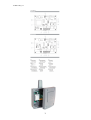
INSTALLATION AND CONNECTIONS
Attach the rear part of the housing to the wall using the plugs and screws supplied. Pass
the cables through the bottom of the receiver. Connect the power cables to the terminals
marked in the mother board, as indicated. Fix the receiver front to the rear part using the
screws supplied.
OPERATING
The pilot lights are activated every 5 seconds to indicate the correct supply of power to the
equipment.
Upon receiving a code, the receiver checks whether it is in its memory, activating the
corresponding relay. The relay activation mode is selected in either impulse or ON/OFF
using the Imp/Bies jumper (only with the relay 2).
PROGRAMMING
MANUAL PROGRAMMING
Press the receiver programming button for 1 sec. and an acoustic signal will be heard. The
receiver will enter standard programming (see table). If the receiver programming button is
held pressed down, the receiver will enter special programming, cyclically passing from
one configuration to the next. Once the programming configuration for the transmitter to be
registered has been chosen, send the code to be programmed by pressing the transmitter.
Every time a transmitter is programmed, the receiver will issue an acoustic signal for 0.5
sec. After 10 seconds without programming or pressing the first two transmitter buttons,
the receiver will exit programming mode, issuing two acoustic signals of 1 sec. If upon
programming a transmitter the receiver memory is full, it will issue 7 acoustic signals of
0.5 sec. and exit programming.

1248003-GB_v1.1
3
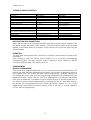
Configuration of transmitter programming in the receiver. Led R1 Led R2
Standard Programming (default option, the receiver is always configured on pluri-channel)
The relays are activated 1st relay by channel 1 and 2nd relay by channel 2 (3rd relay
by channel 1 and 4th relay by channel 2)
Flashing Flashing
Special programming
By pressing any transmitter channel, relay 1 on the receiver will be activated ON OFF
By pressing any transmitter channel, relay 2 on the receiver will be activated OFF ON
By pressing any transmitter channel, the two relays will be activated at the same
time*
ON ON
* If working in ON/OFF activation mode, relay 1 will act as impulse and relay 2 as
ON/OFF. Therefore, on the first press relay 1 will close and open the contact and relay 2
will only close. On the second, relay 1 will close and open the contact and relay 2 will
open.
N.B.: Each transmitter can be configured independently on the receiver.
TOTAL RESET
In programming mode, the programming button is held down and the “MR” reset jumper
is bridged for 3 secs. The receiver will issue 10 short acoustic warning signals followed by
others at a faster pace to indicate that the operation has been successful. The receiver is
now in programming mode.
After 10 seconds without programming or quickly pressing the programming button, the
receiver will exit programming mode, issuing two acoustic signals of 1 sec.
For more information please see our web site www.motion-line.com
USE OF THE RECEIVER
These receivers are designed for use as remote controls for garage doors. Their use is not
guaranteed for directly activating any other equipment different to that specified.
The manufacturer reserves the right to modify equipment specifications without prior
notice.
IMPORTANT ANNEX
Disconnect the power supply before handing the unit.
In compliance with the European Directive low-voltage electrical equipment, we hereby
inform users of the following requirements:
· For units which are permanently connected, an easily accessible circuit-breaker device
must be built into the wiring system.
· This unit must always be installed in a vertical position and firmly fixed to the structure of
the building.
· This unit must only be handled by a specialised installer, by his maintenance staff or by a
duly trained operator.
· The instruction manual for this unit must always remain in the possession of the user.
· Terminals of maximum section 3,8mm2 must be used for the power supply connections.
· Use time delayed fuses.
JCM TECHNOLOGIES, S.A. declares herewith that the product WAVE500, WAVE500-B
complies with the relevant fundamental requirements as per Article 3 of the R&TTE
Directive 1999/5/EG, insofar as the product is used correctly.
-
 1
1
-
 2
2
-
 3
3


JCM Technologies Wave Quick start guide
- Category
- Wall transmitters
- Type
- Quick start guide
- This manual is also suitable for
Ask a question and I''ll find the answer in the document
Finding information in a document is now easier with AI
Related papers

Other documents
-
JCM RBMOT30 / RBMOT500 User guide
-
-
-
 quiko QK-AMBRX User manual
-
-
-
-
CAMDEN DOOR CONTROLS CM-SRFM2 User manual
-
CAMDEN CM-SRFM2 User manual
-
