Page is loading ...

English
AVENTICS | I/O Modules, Digital, AES | R412018146–BAL–001–AF 51
Contents
1 About This Documentation ..................................................................................................... 53
1.1 Documentation validity ............................................................................................................................. 53
1.2 Required and supplementary documentation ................................................................................... 53
1.3 Presentation of information .................................................................................................................... 54
1.3.1 Safety instructions ..................................................................................................................................... 54
1.3.2 Symbols ........................................................................................................................................................ 55
1.3.3 Designations ................................................................................................................................................ 55
1.3.4 Abbreviations .............................................................................................................................................. 55
2 Notes on Safety ........................................................................................................................ 56
2.1 About this chapter ...................................................................................................................................... 56
2.2 Intended use ................................................................................................................................................ 56
2.2.1 Use in explosive atmospheres ............................................................................................................... 56
2.3 Improper use ............................................................................................................................................... 56
2.4 Personnel qualifications .......................................................................................................................... 57
2.5 General safety instructions ..................................................................................................................... 57
2.6 Safety instructions related to the product and technology ........................................................... 58
2.7 Responsibilities of the system owner .................................................................................................. 58
3 General Instructions on Equipment and Product Damage .................................................. 59
4 About This Product .................................................................................................................. 60
4.1 Output module 8DO8M8 and input module 8DI8M8 ........................................................................ 60
4.1.1 Electrical connections ............................................................................................................................... 60
4.1.2 LED ................................................................................................................................................................. 61
4.2 Input module 16DI8M8 ............................................................................................................................. 62
4.2.1 Electrical connections ............................................................................................................................... 62
4.2.2 LED ................................................................................................................................................................. 63
4.3 Output module 8DO4M12 and input module 8DI4M12 ................................................................... 64
4.3.1 Electrical connections ............................................................................................................................... 64
4.3.2 LED ................................................................................................................................................................. 65
4.4 Output module 16DO4M12 and input module 16DI4M12 ............................................................... 66
4.4.1 Electrical connections ............................................................................................................................... 66
4.4.2 LED ................................................................................................................................................................. 67
4.5 Output module 16DO32SC and input module 16DI48SC ................................................................ 69
4.5.1 Electrical connections ............................................................................................................................... 69
4.5.2 LED ................................................................................................................................................................. 71
4.6 Output module 24DODSUB25 ................................................................................................................. 72
4.6.1 Electrical connections ............................................................................................................................... 72
4.6.2 LED ................................................................................................................................................................. 73
4.7 Combination module 8DIDO8M8 ............................................................................................................ 74
4.7.1 Electrical connections ............................................................................................................................... 74
4.7.2 LED ................................................................................................................................................................. 75
4.8 Combination module 8DIDO4M12 ......................................................................................................... 76
4.8.1 Electrical connections ............................................................................................................................... 76
4.8.2 LED ................................................................................................................................................................. 77
5 PLC Configuration of the AV Valve System ........................................................................... 78

52 AVENTICS | I/O Modules, Digital, AES | R412018146–BAL–001–AF
6 Structure of the I/O Module Data ........................................................................................... 79
6.1 Process data ................................................................................................................................................ 79
6.1.1 Output module 8DO8M8 ........................................................................................................................... 79
6.1.2 Input module 8DI8M8 ................................................................................................................................ 79
6.1.3 Input module 16DI8M8 ............................................................................................................................. 79
6.1.4 Output module 8DO4M12 ......................................................................................................................... 80
6.1.5 Input module 8DI4M12 ............................................................................................................................. 80
6.1.6 Output module 16DO4M12 ...................................................................................................................... 80
6.1.7 Input module 16DI4M12 ........................................................................................................................... 81
6.1.8 Output module 16DO32SC ....................................................................................................................... 81
6.1.9 Input module 16DI48SC ............................................................................................................................ 82
6.1.10 Output module 24DODSUB25 ................................................................................................................. 82
6.1.11 Combination module 8DIDO8M8 ............................................................................................................ 82
6.1.12 Combination module 8DIDO4M12 ......................................................................................................... 83
6.2 Diagnostic data ........................................................................................................................................... 83
6.3 Parameter data ........................................................................................................................................... 84
6.3.1 Input modules and output modules ...................................................................................................... 84
6.3.2 Combination modules 8DIDO8M8 and 8DIDO4M12 ......................................................................... 84
7 Commissioning the Valve System ......................................................................................... 85
8 LED Diagnosis on the I/O Modules ......................................................................................... 86
9 Conversion of the Valve System ............................................................................................ 88
9.1 Valve system ............................................................................................................................................... 88
9.2 PLC configuration key for the I/O zone ................................................................................................ 89
9.3 Conversion of the I/O zone ...................................................................................................................... 90
9.3.1 Permissible configurations ..................................................................................................................... 90
9.3.2 Conversion documentation ..................................................................................................................... 91
9.4 New PLC configuration for the valve system ..................................................................................... 91
10 Troubleshooting ...................................................................................................................... 92
10.1 Proceed as follows for troubleshooting .............................................................................................. 92
10.2 Table of malfunctions ............................................................................................................................... 92
11 Technical Data ......................................................................................................................... 94
12 Appendix ................................................................................................................................... 96
12.1 Accessories .................................................................................................................................................. 96
13 Index ......................................................................................................................................... 98

AVENTICS | I/O Modules, Digital, AES | R412018146–BAL–001–AF 53
About This Documentation
English
1 About This Documentation
1.1 Documentation validity
This documentation is valid for I/O modules from the AES series with the following part numbers:
W R412018248, 8-channel digital output module with eight 3-pin M8x1 connections
(8DO8M8)
W R412018233, 8-channel digital input module with eight 3-pin M8x1 connections
(8DI8M8)
W R412018234, 16-channel digital input module with eight 4-pin M8x1 connections
(16DI8M8)
W R412018250, 8-channel digital output module with four 5-pin M12x1 connections
(8DO4M12)
W R412018235, 8-channel digital input module with four 5-pin M12x1 connections
(8DI4M12)
W R412018263, 16-channel digital output module with four 8-pin M12x1 connections
(16DO4M12)
W R412018243, 16-channel digital input module with four 8-pin M12x1 connections
(16DI4M12)
W R412018252, 16-channel digital output module with two sets of 16 spring clamp connections
(16DO32SC)
W R412018242, 16-channel digital input module with three sets of 16 spring clamp connections
(input module 16DI48SC)
W R412018254, 24-channel digital output module with a 25-pin D-SUB connection
(24DODSUB25)
W R412018269, 8-channel digital combination module with eight 3-pin M8x1 connections
(combination module 8DIDO8M8)
W R412018270, 8-channel digital combination module with four 5-pin M12x1 connections
(combination module 8DIDO4M12)
The documentation is geared toward programmers, electrical engineers, service personnel, and
system owners.
This documentation contains important information on the safe and proper commissioning and
operation of the product and how to remedy simple malfunctions yourself.
The system descriptions for bus couplers and valve drivers can be found on the
CD R412018133, included on delivery. Select the appropriate documentation based
on your fieldbus protocol.
1.2 Required and supplementary documentation
O Only commission the product once you have obtained the following documentation and
understood and complied with its contents.
Table 1: Required and supplementary documentation
Documentation Document type Comment
System documentation Operating instructions To be created by system owner
Documentation for PLC configuration tool Software manual Included with software

54 AVENTICS | I/O Modules, Digital, AES | R412018146–BAL–001–AF
About This Documentation
All assembly instructions and system descriptions for the series AES and AV, as well as the
PLC configuration files, can be found on the CD R412018133.
1.3 Presentation of information
To allow you to begin working with the product quickly and safely, uniform safety instructions,
symbols, terms, and abbreviations are used in this documentation. For better understanding, these
are explained in the following sections.
1.3.1 Safety instructions
In this documentation, there are safety instructions before the steps whenever there is a risk of
personal injury or damage to equipment. The measures described to avoid these hazards must
be observed.
Safety instructions are set out as follows:
W Safety sign: draws attention to the risk
W Signal word: identifies the degree of hazard
W Hazard type and source: identifies the hazard type and source
W Consequences: describes what occurs when the safety instructions are not complied with
W Precautions: states how the hazard can be avoided
Assembly instructions for all current
components and the entire AV valve system
Assembly instructions Printed documentation
System descriptions for connecting the
I/O modules and bus couplers electrically
System description PDF file on CD
Table 1: Required and supplementary documentation
Documentation Document type Comment
SIGNAL WORD
Hazard type and source
Consequences
O Precautions
O <List>
Table 2: Hazard classes according to ANSI Z 535.6-2006
Safety sign, signal word Meaning
DANGER
Indicates a hazardous situation which, if not avoided, will certainly result
in death or serious injury.
WARNING
Indicates a hazardous situation which, if not avoided, could result in death
or serious injury.
CAUTION
Indicates a hazardous situation which, if not avoided, could result in minor
or moderate injury.
NOTICE
Indicates that damage may be inflicted on the product or the environment.

AVENTICS | I/O Modules, Digital, AES | R412018146–BAL–001–AF 55
About This Documentation
English
1.3.2 Symbols
The following symbols indicate information that is not relevant for safety but that helps in
comprehending the documentation.
1.3.3 Designations
The following designations are used in this documentation:
1.3.4 Abbreviations
This documentation uses the following abbreviations:
Table 3: Meaning of the symbols
Symbol Meaning
If this information is disregarded, the product cannot be used or operated optimally.
O
Individual, independent action
1.
2.
3.
Numbered steps:
The numbers indicate sequential steps.
Table 4: Designations
Designation Meaning
Backplane Internal electrical connection from the bus coupler to the valve drivers and the
I/O modules
Combination module I/O module with input and output function
Left side I/O zone, located to the left of the bus coupler when facing its electrical connectors
Right side Valve zone, located to the right of the bus coupler when facing its electrical connectors
Stand-alone system Bus coupler and I/O modules without valve zone
Valve driver Electrical valve actuation component that converts the signal from the backplane into
current for the solenoid coil
Table 5: Abbreviations
Abbreviation Meaning
AES Advanced Electronic System
AV Advanced Valve
I/O module Input/Output module
nc Not connected
PLC Programmable Logic Controller, or PC that takes on control functions
UA Actuator voltage (power supply for valves and outputs)
UL Logic voltage (power supply for electronic components and sensors)

56 AVENTICS | I/O Modules, Digital, AES | R412018146–BAL–001–AF
Notes on Safety
2 Notes on Safety
2.1 About this chapter
The product has been manufactured according to the accepted rules of current technology. Even so,
there is risk of injury and damage to equipment if the following chapter and safety instructions of
this documentation are not followed.
O Read these instructions completely before working with the product.
O Keep this documentation in a location where it is accessible to all users at all times.
O Always include the documentation when you pass the product on to third parties.
2.2 Intended use
The devices described in this documentation are electronic components developed for use in the
area of industrial automation technology. They are designed exclusively for use with AV series valve
systems.
The output modules convert output signals from the controller into a 24 V DC output signal with
a maximum current of 0.5 A and forward this signal to the connected actuators. The input modules
transmit electrical input signals from sensors to the controller via the fieldbus connection. The
channels of the combination modules can be individually used as inputs or outputs. They behave like
the channels of the input and output modules. The bus modules of the AES series ensure that an
input channel cannot be actuated as an output.
The devices are intended for professional use only and not for private use. The modules may only be
used for industrial applications (class A). An individual license must be obtained from the authorities
or an inspection center for systems that are to be used in a residential area (residential, business,
and commercial areas). In Germany, these individual licenses are issued by the Regulating Agency
for Telecommunications and Post (Regulierungsbehörde für Telekommunikation und Post, RegTP).
The devices may be used in safety-related control chains if the entire system is geared toward
this purpose.
2.2.1 Use in explosive atmospheres
The devices are not ATEX certified. ATEX certification can only be granted to complete valve systems.
Valve systems may only be operated in explosive atmospheres if the valve system has an ATEX
identification!
O Always observe the technical data and limits indicated on the rating plate for the complete unit,
particularly the data from the ATEX identification.
Conversion of the valve system for use in explosive atmospheres is permissible within the scope
described in the following documents:
W Assembly instructions for the bus couplers and I/O modules
W Assembly instructions for the AV valve system
W Assembly instructions for pneumatic components
2.3 Improper use
Any use other than that described under Intended use is improper and is not permitted.
Improper use of the I/O modules includes:
W Use as a safety component
W Use in explosive areas in a valve system without ATEX certification

AVENTICS | I/O Modules, Digital, AES | R412018146–BAL–001–AF 57
Notes on Safety
English
The installation or use of unsuitable products in safety-relevant applications can result in
unanticipated operating states in the application that can lead to personal injury or damage to
equipment. Therefore, only use a product in safety-relevant applications if such use is specifically
stated and permitted in the product documentation. For example, in areas with explosion protection
or in safety-related components of control systems (functional safety).
AVENTICS GmbH is not liable for any damages resulting from improper use. The user alone bears
the risks of improper use of the product.
2.4 Personnel qualifications
The work described in this documentation requires basic electrical and pneumatic knowledge, as
well as knowledge of the appropriate technical terms. In order to ensure safe use, these activities
may therefore only be carried out by qualified technical personnel or an instructed person under the
direction and supervision of qualified personnel. Qualified personnel are those who can recognize
possible hazards and institute the appropriate safety measures, due to their professional training,
knowledge, and experience, as well as their understanding of the relevant regulations pertaining
to the work to be done. Qualified personnel must observe the rules relevant to the subject area.
2.5 General safety instructions
W Observe the regulations for accident prevention and environmental protection.
W Observe the national regulations for explosive areas.
W Observe the safety instructions and regulations of the country in which the product is used
or operated.
W Only use AVENTICS products that are in perfect working order.
W Follow all the instructions on the product.
W Persons who assemble, operate, disassemble, or maintain AVENTICS products must not
consume any alcohol, drugs, or pharmaceuticals that may affect their ability to respond.
W To avoid injuries due to unsuitable spare parts, only use accessories and spare parts approved
by the manufacturer.
W Comply with the technical data and ambient conditions listed in the product documentation.
W You may only commission the product if you have determined that the end product (such as
a machine or system) in which the AVENTICS products are installed meets the country-specific
provisions, safety regulations, and standards for the specific application.

58 AVENTICS | I/O Modules, Digital, AES | R412018146–BAL–001–AF
Notes on Safety
2.6 Safety instructions related to the product and technology
2.7 Responsibilities of the system owner
As the owner of a system that will be equipped with a series AV valve system, you are responsible for
W ensuring intended use,
W ensuring that operating employees receive regular instruction,
W ensuring that the operating conditions are in line with the requirements for the safe use
of the product,
W ensuring that cleaning intervals are determined and complied with according to environmental
stress factors at the operating site,
W ensuring that, in the presence of an explosive atmosphere, ignition hazards that develop due
to the installation of system equipment are observed,
W ensuring that no unauthorized repairs are attempted if there is a malfunction.
DANGER
Danger of explosion if incorrect devices are used!
There is a danger of explosion if valve systems without ATEX identification are used in an
explosive atmosphere.
O When working in explosive atmospheres, only use valve systems with an ATEX identification
on the rating plate.
Danger of explosion due to disconnection of electrical connections in an explosive atmosphere!
Disconnecting the electrical connections under voltage leads to extreme differences in electrical
potential.
O Never disconnect electrical connections in an explosive atmosphere.
O Only work on the valve system in non-explosive atmospheres.
Danger of explosion caused by defective valve system in an explosive atmosphere!
Malfunctions may occur after the configuration or conversion of the valve system.
O After configuring or converting a system, always perform a function test in a non-explosive
atmosphere before recommissioning.
CAUTION
Risk of uncontrolled movements when switching on the system!
There is a danger of personal injury if the system is in an undefined state.
O Put the system in a safe state before switching it on.
O Make sure that no personnel are within the hazardous zone when the valve system is
switched on.
Danger of burns caused by hot surfaces!
Touching the surfaces of the unit and adjacent components during operation could cause burns.
O Let the relevant system component cool down before working on the unit.
O Do not touch the relevant system component during operation.

AVENTICS | I/O Modules, Digital, AES | R412018146–BAL–001–AF 59
General Instructions on Equipment and Product Damage
English
3 General Instructions on Equipment and
Product Damage
NOTICE
Disconnecting electrical connections while under voltage will destroy the electronic
components of the valve system!
Large differences in potential occur when disconnecting electrical connections under voltage,
which could destroy the valve system.
O Make sure the relevant system component is not under voltage before assembling the valve
system or when connecting and disconnecting it electrically.
Malfunctions in the fieldbus communication due to incorrect or insufficient grounding!
Connected components receive incorrect or no signals. Make sure that the ground connections
of all valve system components are linked
– to each other
– and to ground
with electrically conductive connections.
O Verify proper contact between the valve system and ground.
The valve system contains electronic components that are sensitive to electrostatic discharge
(ESD)!
If the electrical components are touched by persons or objects, this may lead to an electrostatic
discharge that could damage or destroy the components of the valve system.
O Ground the components to prevent electrostatic charging of the valve system.
O Use wrist and shoe grounding straps, if necessary, when working on the valve system.

60 AVENTICS | I/O Modules, Digital, AES | R412018146–BAL–001–AF
About This Product
4 About This Product
4.1 Output module 8DO8M8 and input module 8DI8M8
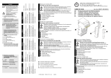
Figure 1 contains a device overview for the output module 8DO8M8 and input module 8DI8M8.
Only the 8DO8M8 output module is shown in the figure. The only variations in input module
8DI8M8 are the designations for the connections and the LEDs used to monitor the power supply.
Fig. 1: Device overview for output module 8DO8M8 and input module 8DI8M8
4.1.1 Electrical connections
Power supply The bus coupler supplies the power for the I/O modules via the electrical backplane connections (10)
and (12). The I/O modules do not contain any additional power supply connections.
Output connections The output module is equipped with 8 output connections for actuators. These are designed as
M8 sockets, female, 3-pin, A-coded. The connection IDs are X2O1 to X2O8.
O See table 6 for the pin assignments of the output connections X2O1 to X2O8.
1DIAG LED for module diagnosis
2 LED for monitoring power supply UA
(output module)
3 LED for monitoring power supply UL
(input module)
4 PLC configuration key
5 Material (part) number
6 Signal input/output
7 Field for channel and connection label
8 Channel-related LED for input or output
signals
9 Field for equipment ID
10 Electrical connection for AES modules
(female)
11 Rating plate
12 Electrical connection for AES modules (male)
R412018248
8DO8M8
X2O1
0
DIAG
UA
1
3
5
7
2
4
6
X2O2
X2O3
X2O4
X2O5
X2O6
X2O7
X2O8
11
1
2
3
4
5
6
7
8
9
10
12

AVENTICS | I/O Modules, Digital, AES | R412018146–BAL–001–AF 61
About This Product
English
The cable length must not exceed 30 m.
Input connections The input module is equipped with eight input connections for sensors. These are designed as
M8 sockets, female, 3-pin, A-coded. The connection IDs are X2I1 to X2I8.
The sensor voltage is supplied via pin 1 and pin 3.
O See table 7 for the pin assignments of the input connections X2I1 to X2I8.
The cable length must not exceed 30 m. The total current for all sensor supplies on an input module
must not exceed 1 A.
4.1.2 LED
The I/O modules have module-related and channel-related LEDs. The module-related LEDs (1), (2)
and (3) have voltage and short-circuit monitoring functions.
The channel-related LEDs (8) are composed of two semicircles arranged around the socket. Both
LEDs are illuminated
W on the output module when the corresponding output switches to 24 V DC
W on the input module when a signal is present at the respective input.
The LED functions are described in the tables below. For a comprehensive description of the LEDs,
see “8 LED Diagnosis on the I/O Modules” on page 86.
UA
1
3
4
1
Table 6: Pin assignments of output connections
Pin Sockets X2O1 to X2O8
Pin 1 nc (not connected)
Pin 3 0 V DC actuator voltage
Pin 4 24 V DC output signal
1)
1)
Maximum 0.5 A, short-circuit-proof, inductive shutdown voltage limited to 47 V DC
UL
1
3
4
1
Table 7: Pin assignments of input connections
Pin Sockets X2I1 to X2I8
Pin 1 24 V DC sensor voltage
1)
1)
Derived from the UL voltage
Pin 3 0 V DC sensor voltage
Pin 4 Input signal
DIAG UA
0
1
Output module 8DO8M8
12 38
8
Table 8: Meaning of the LEDs on output module 8DO8M8 in normal mode
Designation Function Color in normal mode
DIAG (1) Monitors diagnostic reporting of the modules Off
UA (2) Monitors the actuator voltage (UA) Illuminated green
– (3)None –
Channel-related
LEDs 0 – 7 (8)
Monitors the output Illuminated yellow when an
output signal is present
DIAG UL
0
1
Input module 8DI8M8
12 38
8
Table 9: Meaning of the LEDs on input module 8DI8M8 in normal mode
Designation Function State in normal mode
DIAG (1) Monitors diagnostic reporting of the modules Off
– (2)None –
UL (3) Monitors the sensor voltage (UL) Illuminated green
Channel-related
LEDs 0 – 7 (8)
Monitors the input Illuminated green when an input
signal is present.

62 AVENTICS | I/O Modules, Digital, AES | R412018146–BAL–001–AF
About This Product
4.2 Input module 16DI8M8
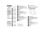
Figure 2 contains a device overview for the input module 16DI8M8.
Fig. 2: Device overview for input module 16DI8M8
4.2.1 Electrical connections
Power supply The bus coupler supplies the power for the I/O modules via the electrical backplane connections (10)
and (12). The I/O modules do not contain any additional power supply connections.
The cable length must not exceed 30 m.
Input connections The input module is equipped with eight input connections for sensors. These are designed as
M8 sockets, female, 4-pin, A-coded. The connection IDs are X2I1 to X2I8.
The sensor voltage is supplied via pin 1 and pin 3.
O See table 10 for the pin assignments of the input connections X2I1 to X2I8.
1DIAG LED for module diagnosis
2 LED (not connected)
3 LED for monitoring power supply UL
(input module)
4 PLC configuration key
5 Material (part) number
6 Signal input
7 Field for channel and connection label
8 Channel-related LED for input or output
signals
9 Field for equipment ID
10 Electrical connection for AES modules
(female)
11 Rating plate
12 Electrical connection for AES modules (male)
R412018234
16DI8M8
X2I1
2
3
DIAG
0
1
4
5
8
9
12
13
6
7
10
11
14
15
X2I2
X2I3
X2I4
X2I5
X2I6
X2I7
X2I8
UL
11
1
3
4
5
6
7
8
9
10
12
2
2
3
UL
4
3
2
1
Table 10: Pin assignments of input connections
Pin Sockets X2I1 to X2I8
Pin 1 24 V DC sensor voltage
1)
1)
Derived from the UL voltage
Pin 2 Input signal (higher order bit)
Pin 3 0 V DC sensor voltage
Pin 4 Input signal (lower order bit)

AVENTICS | I/O Modules, Digital, AES | R412018146–BAL–001–AF 63
About This Product
English
The cable length must not exceed 30 m. The total current for all sensor supplies on an input module
must not exceed 1 A.
4.2.2 LED
The I/O modules have module-related and channel-related LEDs. The module-related LEDs (1), (2)
and (3) have voltage and short-circuit monitoring functions.
The channel-related LEDs (8) are composed of two semicircles arranged around the socket. The top
semicircle is illuminated with the lower order bit and the bottom semicircle is illuminated with the
higher order bit,
W on the input module when a signal is present at the respective input.
The table below describes the functions of the LEDs. For a comprehensive description of the LEDs,
see “8 LED Diagnosis on the I/O Modules” on page 86.
DIAG UL
2
3
0
1
Input module 16DI8M8
12 38
8
Table 11: Meaning of the LEDs on input module 16DI8M8 in normal mode
Designation Function State in normal mode
DIAG (1) Monitors diagnostic reporting of the modules Off
– (2)None –
UL (3) Monitors the sensor voltage (UL) Illuminated green
Channel-related
LEDs 0 – 15 (8)
Monitors the input Illuminated green when an input signal
is present.

64 AVENTICS | I/O Modules, Digital, AES | R412018146–BAL–001–AF
About This Product
4.3 Output module 8DO4M12 and input module 8DI4M12
Figure 3 contains a device overview for the output module 8DO4M12 and input module 8DI4M12.
Only the 8DO4M12 output module is shown in the figure. The only variations in input module
8DI4M12 are the designations for the connections and the LED used to monitor the power supply.
Fig. 3: Device overview for output module 8DO4M12 and input module 8DI4M12
4.3.1 Electrical connections
Power supply The bus coupler supplies the power for the I/O modules via the electrical backplane connections (10)
and (12). The I/O modules do not contain any additional power supply connections.
Output connections The output module is equipped with 4 output connections for actuators. These are designed as
M12 sockets, female, 5-pin, A-coded. The connection IDs are X2O1 to X2O4.
O See table 12 for the pin assignments of the output connections X2O1 to X2O4.
1DIAG LED for module diagnosis
2 LED for monitoring power supply UA
(output module)
3 LED for monitoring power supply UL
(input module)
4 PLC configuration key
5 Part No.
6 Signal input/output
7 Field for channel and connection label
8 Channel-related LED for input or output
signals
9 Field for equipment ID
10 Electrical connection for AES modules
(female)
11 Rating plate
12 Electrical connection for AES modules (male)
R412018250
8DO4M12
X2O1
DIAG
UA
0
1
4
5
2
3
6
7
X2O2
X2O3
X2O4
11
1
2
3
4
5
6
7
8
9
10
12

AVENTICS | I/O Modules, Digital, AES | R412018146–BAL–001–AF 65
About This Product
English
The cable length must not exceed 30 m.
Input connections The input module is equipped with 4 input connections for sensors. These are designed as
M12 sockets, female, 5-pin, A-coded. The connection IDs are X2I1 to X2I4.
The sensor voltage is supplied via pin 1 and pin 3.
O See table 13 for the pin assignments of the input connections X2I1 to X2I4.
The cable length must not exceed 30 m. The total current for all sensor supplies on an input module
must not exceed 1 A.
4.3.2 LED
The I/O modules have module-related and channel-related LEDs. The module-related LEDs (1), (2)
and (3) have voltage and short-circuit monitoring functions.
The channel-related LEDs (8) are composed of two semicircles arranged around the socket. The top
semicircle is illuminated with the lower order bit and the bottom semicircle is illuminated with the
higher order bit,
W on the output module when the corresponding output switches to 24 V DC
W on the input module when a signal is present at the respective input.
The LED functions are described in the tables below. For a comprehensive description of the LEDs,
see “8 LED Diagnosis on the I/O Modules” on page 86.
UA
1
X2O1
0
3
2
5
4
1
Table 12: Pin assignments of output connections
Pin Sockets X2O1 to X2O4
Pin 1 nc (not connected)
Pin 2 24 V DC output signal
1)
(higher order bit)
1)
Maximum 0.5 A, short-circuit-proof, inductive shutdown voltage limited to 47 V DC
Pin 3 0 V DC actuator voltage
Pin 4 24 V DC output signal
1)
(lower order bit)
Pin 5 nc
UL
1
X2I1
0
3
2
5
4
1
Table 13: Pin assignments of input connections
Pin Sockets X2I1 to X2I4
Pin 1 24 V DC sensor voltage
1)
1)
Derived from the UL voltage
Pin 2 Input signal (higher order bit)
Pin 3 0 V DC sensor voltage
Pin 4 Input signal (lower order bit)
Pin 5 nc
DIAG UA
1
X2O1
2
0
Output module 8DO4M12
12 38
Table 14: Meaning of the LEDs on output module 8DO4M12 in normal mode
Designation Function Color in normal mode
DIAG (1) Monitors diagnostic reporting of the modules Off
UA (2) Monitors the actuator voltage (UA) Illuminated green
– (3)None –
Channel-related
LEDs 0 – 7 (8)
Monitors the output Illuminated yellow when an output
signal is present
DIAG UL
1
X2I1
0
2
Input module 8DI4M12
12 38
Table 15: Meaning of the LEDs on input module 8DI4M12 in normal mode
Designation Function State in normal mode
DIAG (1) Monitors diagnostic reporting of the modules Off
– (2)None –
UL (3) Monitors the sensor voltage (UL) Illuminated green
Channel-related
LEDs 0 – 7 (8)
Monitors the input Illuminated green when an input signal
is present.

66 AVENTICS | I/O Modules, Digital, AES | R412018146–BAL–001–AF
About This Product
4.4 Output module 16DO4M12 and input module 16DI4M12
Figure 4 contains a device overview for the output module 16DO4M12 and input module 16DI4M12.
Only the 16DO4M12 output module is shown in the figure. The only variations in input module
16DI4M12 are the designations for the connection and the LEDs used to monitor the power supply.
Fig. 4: Device overview for output module 16DO4M12 and input module 16DI4M12
4.4.1 Electrical connections
Power supply The bus coupler supplies the power for the I/O modules via the electrical backplane connections (10)
and (12). The I/O modules do not contain any additional power supply connections.
Output connections The output module is equipped with 4 output connections for actuators. These are designed as
M12 sockets, female, 8-pin, A-coded. The connection IDs are X2O1 to X2O4.
O See table 16 for the pin assignments of the output connections X2O1 to X2O4.
1DIAG LED for module diagnosis
2 LED for monitoring power supply UA (output
module)
3 LED for monitoring power supply UL (input
module)
4 PLC configuration key
5 Material (part) number
6 Signal input/output
7 Field for channel and connection label
8 LED segments without function
9 Field for equipment ID
10 Electrical connection for AES modules
(female)
11 Rating plate
12 Electrical connection for AES modules (male)
R412018263
16DO4M12
X2O1
DIAG
UA
0
1
4
5
2
3
6
7
X2O2
X2O3
X2O4
11
1
2
3
4
5
6
7
8
9
10
12

AVENTICS | I/O Modules, Digital, AES | R412018146–BAL–001–AF 67
About This Product
English
The cable length must not exceed 30 m.
Input connections The input module is equipped with 4 input connections for sensors. These are designed as
M12 sockets, female, 8-pin
,
A-coded. The connection IDs are X2I1 to X2I4.
The sensor voltage is supplied via pin 5 and pin 7.
O See table 17 for the pin assignments of the input connections X2I1 to X2I4.
The cable length must not exceed 30 m. The total current for all sensor supplies on an input module
must not exceed 1 A.
4.4.2 LED
The I/O modules have only module-related and no channel-related LEDs. The module-related LEDs
(1), (2) and (3) have voltage and short-circuit monitoring functions. The segments of the channel-
related LEDs (8) are present but have no function.
The LED functions are described in the tables below. For a comprehensive description of the LEDs,
see “8 LED Diagnosis on the I/O Modules” on page 86.
UA
1
X2O1
0
2
4
5
3
1
6
7
8
Table 16: Pin assignments of output connections
Pin Sockets X2O1 to X2O4
Pin 1 24 V DC output signal
1)
(bit X.0 or X.4)
1)
Maximum 0.5 A, short-circuit-proof, inductive shutdown voltage limited to 47 V DC
Pin 2 24 V DC output signal
1)
(bit X.1 or X.5)
Pin 3 24 V DC output signal
1
)
(bit X.2 or X.6)
Pin 4 24 V DC output signal
1
)
(bit X.3 or X.7)
Pin 5 nc
Pin 6 nc
Pin 7 0 V DC actuator voltage
Pin 8 nc
UL
1
X2I1
0
2
4
5
3
1
6
7
8
Table 17: Pin assignments of input connections
Pin Sockets X2I1 to X2I4
Pin 1 Input signal (bit X.0 or X.4)
Pin 2 Input signal (bit X.1 or X.5)
Pin 3 Input signal (bit X.2 or X.6)
Pin 4 Input signal (bit X.3 or X.7)
Pin 5 24 V DC sensor voltage
1)
1)
Derived from the UL voltage
Pin 6 nc
Pin 7 0 V DC sensor voltage
Pin 8 nc
DIAG UA
1
X2O1
2
0
Output module 16DO4M12
12 38
Table 18: Meaning of the LEDs on output module 16DO4M12 in normal mode
Designation Function Color in normal mode
DIAG (1) Monitors diagnostic reporting of the modules Off
UA (2) Monitors the actuator voltage (UA) Illuminated green
– (3)None –
Channel-related
LEDs 0 – 7 (8)
None –

68 AVENTICS | I/O Modules, Digital, AES | R412018146–BAL–001–AF
About This Product
DIAG UL
1
X2I1
0
2
Input module 16DI4M12
12 38
Table 19: Meaning of the LEDs on input module 16DI4M12 in normal mode
Designation Function State in normal mode
DIAG (1) Monitors diagnostic reporting of the modules Off
– (2)None –
UL (3) Monitors sensor voltage (UL) Illuminated green
Channel-related
LEDs 0 – 7 (8)
None –

AVENTICS | I/O Modules, Digital, AES | R412018146–BAL–001–AF 69
About This Product
English
4.5 Output module 16DO32SC and input module 16DI48SC
Figure 5 contains a device overview for the output module 16DO32SC and input module 16DI48SC.
The input module 16DI48SC differs from the output module 16DO32SC in the designations for
the connections and the LEDs used to monitor the power supply. The input module 16DI48SC
has an additional third row with terminals.
Fig. 5: Device overview for output module 16DO32SC and input module 16DI48SC
4.5.1 Electrical connections
Power supply The bus coupler supplies the power for the I/O modules via the electrical backplane connections (10)
and (12). The I/O modules do not contain any additional power supply connections.
Output connections The output module is equipped with two rows with 16 output connections for actuators. These
consist of spring clamp connections. The IDs of the connection rows are X2O1 and X2O2. The
contacts of the connection rows are numbered from 1 –16.
O See table 20 for the pin assignments of the output connections
X2O1
and
X2O2.
R412018252
16DO16SC
DIAG
UA
DIAG UA
R412018242
16DI16SC
DIAG
UA
11
12 3
7
10
12
9
8
6
5
4
6
16DO32SC 16DI48SC
1DIAG LED for module diagnosis
2 LED for monitoring power supply UA
(output module)
3 LED for monitoring power supply UL
(input module)
4 PLC configuration key
5 Material (part) number
6 Signal input/output
7 Field for channel and connection label
8 Channel-related LED for input or output
signals
9 Field for equipment ID
10 Electrical connection for AES modules
(female)
11 Rating plate
12 Electrical connection for AES modules (male)

70 AVENTICS | I/O Modules, Digital, AES | R412018146–BAL–001–AF
About This Product
The cable length must not exceed 30 m.
Input connections The input module has three rows with 16 input connections for sensors. These consist of spring
clamp connections. The IDs of the connection rows are X2I1–X2I3. The contacts of the connection
rows are numbered from 1 –16.
The sensor voltage is supplied by the module via the contacts of the connections X2I2 and X2I3.
O See table 21 for the pin assignments of the input connections X2I1 to X2I3.
Table 20: Pin assignments of output connections
Port Contact Allocation
X2O1 1 24 V DC output signal
1)
(bit 0.0)
1)
Maximum 0.5 A, short-circuit-proof, inductive shutdown voltage limited to 47 V DC
2 24 V DC output signal
1)
(bit 0.1)
3 24 V DC output signal
1)
(bit 0.2)
4 24 V DC output signal
1)
(bit 0.3)
5 24 V DC output signal
1)
(bit 0.4)
6 24 V DC output signal
1)
(bit 0.5)
7 24 V DC output signal
1)
(bit 0.6)
8 24 V DC output signal
1)
(bit 0.7)
9 24 V DC output signal
1)
(bit 1.0)
10 24 V DC output signal
1)
(bit 1.1)
11 24 V DC output signal
1)
(bit 1.2)
12 24 V DC output signal
1)
(bit 1.3)
13 24 V DC output signal
1)
(bit 1.4)
14 24 V DC output signal
1)
(bit 1.5)
15 24 V DC output signal
1)
(bit 1.6)
16 24 V DC output signal
1)
(bit 1.7)
X2O2 1–16 0 V DC actuator voltage
Table 21: Pin assignments of input connections
Port Contact Allocation
X2I1 1 Input signal (bit 0.0)
2 Input signal (bit 0.1)
3 Input signal (bit 0.2)
4 Input signal (bit 0.3)
5 Input signal (bit 0.4)
6 Input signal (bit 0.5)
7 Input signal (bit 0.6)
8 Input signal (bit 0.7)
9 Input signal (bit 1.0)
10 Input signal (bit 1.1)
11 Input signal (bit 1.2)
12 Input signal (bit 1.3)
13 Input signal (bit 1.4)
14 Input signal (bit 1.5)
15 Input signal (bit 1.6)
16 Input signal (bit 1.7)
X2I2 1–16 24 V DC sensor voltage
1)
1)
Derived from the UL voltage
X2I3 1–16 0 V DC sensor voltage
/