Page is loading ...


Subject to technical changes.
© Mettler-Toledo AG 02 / 2015.
Printed in Switzerland. 52 121 404


4
1 Operation
Entry of data values, selection of data entry options
Use the key to increase or the key to decrease a digit. Use the same keys to navigate
within a selection of values or options of a data entry field.
Note: Some screens require configuring multiple values via the same data field (ex: configuring
multiple setpoints). Be sure to use the or key to return to the primary field and the
or key to toggle between all configuration options before entering to the next display screen.
Navigation with
ì in Display
If a
ì is displayed on the bottom right hand corner of the display, you can use the
or the key to navigate to it. If you click [ENTER] you will navigate backwards through
the menu (go back one screen). This can be a very useful option to move back up the menu tree
without having to exit into the measuring mode and re-enter the menu.
Exit menu
Note: Exit the menu at any time by pressing the and key simultaneously (escape).
The transmitter returns to the Measurement mode.
”Save changes” dialog
Three options are possible for the ”Save changes” dialog:
– ”Yes & Exit”: Save changes and exit to measuring mode
– ”Yes &
ì”: Save changes and go back one screen
– ”No & Exit”: Don’t save changes and exit to measuring mode
The ”Yes &
ì” option is very useful if you want to continue configuring without having to
re-enter the menu.
ì

5
2 Menu Structure
Measurement
Mode M300
CalMenu Info
Quick Setup
Configure
System PID Setup Service
Messages
Measurement
Analog Outputs
Set Points
Alarm
Display
Hold Outputs
Set Language
USB
Passwords
Set/Clear Lockout
Reset
PID Setup
Tune Parameters
Mode
Diagnostics
Calibrate
Tech Service
Model/Software
Revision

6
3 Terminal Block (TB) definitions
Power connections are labeled –Nfor Neutral and +L for Line, for 100 to 240 VAC or 20– 30 VDC.
1
⁄4 DIN
1
⁄2 DIN
NO = normally open (contact is open if unactuated).
NC = normally closed (contact is closed if unactuated).
3.1 Sensor Connections – TB3 / TB4*
AJ and AIN refer to connections for channel A.
* For four channel models only.
Pin no. Transmitter Function
TB3 TB4*
1– Not used
2 GND Ground
3 BJ* DJ* +10 VDC
4 BIN* DIN* Flow Pulse Input
5 +5 V +5 VDC
6 GND Ground
7 AJ CJ* +10 VDC
8 AIN CLN* Flow Pulse Input
9 +5 V +5 VDC
TB1A for
1
⁄4 DIN
1 NO2
2 COM2
3 NC2
4 NO6*
5 COM6*
6 NO4
7 COM4
TB1B for
1
⁄4 DIN
1 NO1
2 COM1
3 NC1
4 NC5*
5 COM5*
6 NO3
7 COM3
TB2 for
1
⁄4 DIN
1 AO1+
2 AO1–/AO2–
3 AO2+
4 AO3+*
5 AO3–/AO4–*
6 AO4+*
7 DI1+
8 DI1–/DI2–*
9 DI2+*
TB2 for
1
⁄2 DIN
1 AO1+
2 AO1–/AO2–
3 AO2+
4 AO3+*
5 AO3–/AO4–*
6 AO4+*
7 DI1+
8 DI1–/DI2–*
9 DI2+*
1 NO1
2 COM1
3 NC1
4 NO2
5 COM2
6 NC2
7 COM5*
8 NC5*
9 COM6*
10 NO6*
11 NO3
12 COM3
13 NO4
14 COM4
TB4
TB2
TB3
TB1A
TB1B
1 7
1 7
9
1
9
1
9
1
TB2 TB3
TB4
TB1
1 14
1 9 1 9 1 9
TB1 for
1
⁄2 DIN
* Dual-
Channel
only

7
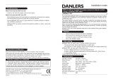
4 Wiring for Common Flow Sensors (using TB3/TB4)
Sensor wiring for most flow sensors is shown below. For other sensors, please see the instruction
manual. Wiring is shown for channel A. Refer to section 3.1 for channels B, C and D.
Kit 58 091 032 supplied with the M300 includes 4 each of the capacitors and resistors shown in the
diagrams below, plus wire nuts for use in completing the wiring.
THORNTON 33142-33145,
33159-33162, 33273
Badger
(formerly Data Industrial 200 Series)
Flow Sensors
Type: high
M300 transmitter
black
shield
red
1K
0.33uF
TB 3
1
2 GND
3
4
5 +5V
6 GND
7 A J
8 A IN
9 +5V

8
Wiring for Common Flow Sensors (using TB3/TB4)
THORNTON
33174-33177, 33171, 33172
Badger
(formerly Data Industrial 4000 Series)
Flow Sensors
Type: high
M300 transmitter
black
shield
red
clear
0.33uF
TB 3
1
2 GND
3
4
5 +5V
6 GND
7 A J
8 A IN
9 +5V
THORNTON
33336-333377 (Hoffer)
33441-33450 (Sponsler)
Hoffer and Sponsler
Turbine sensors
Type: high
M300 transmitter
black
shield
red
white or orange
0.33uF
TB 3
1
2 GND
3
4
5 +5V
6 GND
7 A J
8 A IN
9 +5V

9
THORNTON 33282, 33285,
33287, 33298-33305
Signet 2507, 2536, 2540
Hall-Effect
Paddlewheel Sensor, Type: high
M300 transmitter
shield
red
black
10K
0.33uF
TB 3
1
2 GND
3
4
5 +5V
6 GND
7 A J
8 A IN
9 +5V
THORNTON 33189, 33193,
33195, 33196, 33229
Signet 515 Sensor
Type: low
M300 transmitter
black
shield
red
TB 3
1
2 GND
3
4
5 +5V
6 GND
7 A J
8 A IN
9 +5V

10
5 Quick Setup (PATH: Menu/Quick Setup)
Quick Setup allows limited configuration of the most common functions of the M300 Flow transmitter.
Detailed information for each function can be found in the individual sections of the manual.
Enter Quick Setup mode
While in Measurement mode press to bring up the Menu selection. Select «Quick
Setup» and press the [ENTER] key.
Note: To exit Quick Setup mode at any time press the and keys simultaneous-
ly (Escape). The transmitter returns to the Measurement mode and the old values
remain active.
Flow Sensor Type Selection
Refer to Section 4 for Flow sensor type information.
Select the desired flow sensor type which corresponds to the type of flow sensor wired
to the transmitter. The choices are High, Low and Type 2.
Measurement Selection
Select the desired line (a or c) to configure the values to be displayed and whether this
value will have an Analog Output.
Convention:
1st line on display = > a
3rd line on display = > c
Example:
– By selecting a and GPM as units, the flow rate value will be displayed on the 1st line.
– By selecting c and Gals as units, the total flow value will be displayed on the 3rd line
of the display which has more digits of resolution.
– Selecting None means the display will be blank for the line selected.
75.5 GPM
0.000 Gals
75.5 GPM
283.9 L/min
a GPM
Analog Output? Yes
ì
75.5 GPM
283.9 L/min
Sensor Type Input High
ì
75.5 GPM
283.9 L/min
MENU
Quick Setup

11
Analog Outputs
By selecting Analog Output Yes on the previous screen the linear 4–20 mA analog out-
put Aout1 will be setup for measurement a or Aout2 for measurement c when [ENTER]
is pressed. Selecting No means that no analog output is setup.
Aout min and Aout max are the minimum and maximum measurement values for the
4 and 20 mA signal limits respectively.
Set points
After configuring the Analog Output, a Set Point can be configured for that measure-
ment. If No is selected and [ENTER] is pressed then the Quick Setup is done and
the menus are exited without setting any set point.
Selecting Yes and pressing [ENTER] means a Set Point can be configured.
The following Set Point Types can be selected:
– Off (Set Point is Off)
– High (High value has to be set)
– Low (Low value has to be set)
– Outside (High and Low value have to be set)
– Between (High and Low value have to be set)
After setting the Set point value(s) a Relay (none (blank), 1, 2, 3, 4) can be con -
figured for that Set Point, including delay and hysteresis.
If Yes and [ENTER] is pressed, the display, analog output, set point and relay setups
are stored and the previous values including use of the relay are cancelled.
If No and [ENTER] is pressed then no changes are made and the transmitter will
return to the normal operating mode.
75.5 GPM
Save Change Yes
Press Enter to Exit
ì
75.5 GPM
SP1 use Relay #1
ì
75.5 GPM
SP1 High = 0.000
ì
75.5 GPM
a Set Point Yes
SP1 Type= High
ì
75.5 G
PM
Aout1 min= 0.000 GPM
Aout1 max= 0.000 GPM
ì

12
6 Entering Calibration Constants (PATH: Cal/Sensor/Edit)
K-factors are supplied with flow sensor documentation, and need to be identified for the specific sensor
pipe size, converted to appropriate units if necessary, and entered for each channel. If a certificate of
calibration with multipoint linearization is provided (some vortex and turbine sensors) refer to the
instruction manual. Multiplier units entered into the M300 must be pulses per gallon, even if the readout
will be in other units. Enter Adder constants (if provided) in units of GPM.
If K factors are provided in units of GPM/Hz, divide 60 by the K value and enter the result as the
Multiplier, ”M”. For example, a K value of 2 GPM/Hz would result in a Multiplier of 60/2 = 30.
If an offset is provided in Hz, multiply it by the original K factor (in GPM/Hz) and enter the result as the
Adder, ”A”. If an offset is not provided, leave the Adder set to zero.
While in Measurement mode press the key. Press the or key to select
”Sensor”. For 4 channel models, select the channel.
Select ”Edit”.
Press Enter to display all calibration constants for the sensor. Change the K-factor ”M”
and Adder ”A”. If no adder is provided, leave this as 0.
75.00 GPM
M= 1.0000 A=0.0000
ì
75.00 GPM
Calibrate Sensor
Channel A Edit
ì
75.00 GPM
Calibrate Sensor
Channel A GPM
ì

13
For multipoint data, please refer to the instruction manual.
Select Yes to save the new calibration values and the successful Calibration is con-
firmed on the display.
75.00 GPM
K1=100.000 F1=0.0000
K2=100.000 F2=0.0000
75.00 GPM
Save Calibration Yes
Press Enter to Exit
ì

20
Verkabelung für handelsübliche Durchflusssensoren (mit TB3/TB4)
THORNTON
33174-33177, 33171, 33172
Badger
(formerly Data Industrial 4000 Series)
Flow Sensors
Type: high
M300 transmitter
black
shield
red
clear
0.33uF
TB 3
1
2 GND
3
4
5 +5V
6 GND
7 A J
8 A IN
9 +5V
THORNTON
33336-333377 (Hoffer)
33441-33450 (Sponsler)
Hoffer and Sponsler
Turbine sensors
Type: high
M300 transmitter
black
shield
red
white or orange
0.33uF
TB 3
1
2 GND
3
4
5 +5V
6 GND
7 A J
8 A IN
9 +5V

21
THORNTON 33282, 33285,
33287, 33298-33305
Signet 2507, 2536, 2540
Hall-Effect
Paddlewheel Sensor, Type: high
M300 transmitter
shield
red
black
10K
0.33uF
TB 3
1
2 GND
3
4
5 +5V
6 GND
7 A J
8 A IN
9 +5V
THORNTON 33189, 33193,
33195, 33196, 33229
Signet 515 Sensor
Type: low
M300 transmitter
black
shield
red
TB 3
1
2 GND
3
4
5 +5V
6 GND
7 A J
8 A IN
9 +5V

32
Câblage des sondes de débit classiques (à l’aide du TB3/TB4)
THORNTON
33174-33177, 33171, 33172
Badger
(formerly Data Industrial 4000 Series)
Flow Sensors
Type: high
M300 transmitter
black
shield
red
clear
0.33uF
TB 3
1
2 GND
3
4
5 +5V
6 GND
7 A J
8 A IN
9 +5V
THORNTON
33336-333377 (Hoffer)
33441-33450 (Sponsler)
Hoffer and Sponsler
Turbine sensors
Type: high
M300 transmitter
black
shield
red
white or orange
0.33uF
TB 3
1
2 GND
3
4
5 +5V
6 GND
7 A J
8 A IN
9 +5V

33
THORNTON 33282, 33285,
33287, 33298-33305
Signet 2507, 2536, 2540
Hall-Effect
Paddlewheel Sensor, Type: high
M300 transmitter
shield
red
black
10K
0.33uF
TB 3
1
2 GND
3
4
5 +5V
6 GND
7 A J
8 A IN
9 +5V
THORNTON 33189, 33193,
33195, 33196, 33229
Signet 515 Sensor
Type: low
M300 transmitter
black
shield
red
TB 3
1
2 GND
3
4
5 +5V
6 GND
7 A J
8 A IN
9 +5V

44
Cablaggio per i sensori di flusso comuni (utilizzando TB3/TB4)
THORNTON
33174-33177, 33171, 33172
Badger
(formerly Data Industrial 4000 Series)
Flow Sensors
Type: high
M300 transmitter
black
shield
red
clear
0.33uF
TB 3
1
2 GND
3
4
5 +5V
6 GND
7 A J
8 A IN
9 +5V
THORNTON
33336-333377 (Hoffer)
33441-33450 (Sponsler)
Hoffer and Sponsler
Turbine sensors
Type: high
M300 transmitter
black
shield
red
white or orange
0.33uF
TB 3
1
2 GND
3
4
5 +5V
6 GND
7 A J
8 A IN
9 +5V

45
THORNTON 33282, 33285,
33287, 33298-33305
Signet 2507, 2536, 2540
Hall-Effect
Paddlewheel Sensor, Type: high
M300 transmitter
shield
red
black
10K
0.33uF
TB 3
1
2 GND
3
4
5 +5V
6 GND
7 A J
8 A IN
9 +5V
THORNTON 33189, 33193,
33195, 33196, 33229
Signet 515 Sensor
Type: low
M300 transmitter
black
shield
red
TB 3
1
2 GND
3
4
5 +5V
6 GND
7 A J
8 A IN
9 +5V

56
Cableado para sensores de flujo comunes (utilizando TB3/TB4)
THORNTON
33174-33177, 33171, 33172
Badger
(formerly Data Industrial 4000 Series)
Flow Sensors
Type: high
M300 transmitter
black
shield
red
clear
0.33uF
TB 3
1
2 GND
3
4
5 +5V
6 GND
7 A J
8 A IN
9 +5V
THORNTON
33336-333377 (Hoffer)
33441-33450 (Sponsler)
Hoffer and Sponsler
Turbine sensors
Type: high
M300 transmitter
black
shield
red
white or orange
0.33uF
TB 3
1
2 GND
3
4
5 +5V
6 GND
7 A J
8 A IN
9 +5V
/