Page is loading ...

EXPORT CONTROL WARNING: This document contains controlled technical data
under the jurisdiction of the Export Administration Regulations (EAR), 15 CFR
730-774. It cannot be transferred to any foreign third party without the specific prior
approval of the U.S. Department of Commerce, Bureau of Industry and Security (BIS).
Violations of these regulations are punishable by fine, imprisonment, or both.
ATB-7300
Avionics Test Bench
Operation Manual

ATB-7300
Avionics Test Bench
Operation Manual
COPYRIGHT Aeroflex 2015
All rights reserved. No part of this publication may be reproduced, stored in a retrieval system, or
transmitted in any form or by any means, electronic, mechanical, photocopying, recording or otherwise
without the prior permission of the publisher.
Manual Number: 89304 (CD)
Revision A0 July 14, 2011
Revision A1 November 04, 2011
Revision A2 February 10, 2014
Revision B0 May 9, 2014
Revision C0 August 03, 2015
This document contains controlled technical data under the jurisdiction of the Export Administration
Regulations (EAR), 15 CFR 730-774. It cannot be transferred to any foreign third party without the
specific prior approval of the U.S. Department of Commerce Bureau of Industry and Security (BIS).
Violations of these regulations are punishable by fine, imprisonment, or both.
10200 West York / Wichita, Kansas 67215 U.S.A. / (316) 522-4981 / FAX (316) 524-2623
www.aeroflex.com

Subject to Export Control, see Cover Page for details.
i
Precautions
SAFETY FIRST - TO ALL OPERATIONS PERSONNEL
GENERAL CONDITIONS OF USE
This product is designed and tested to comply with the requirements of IEC/EN61010-1 ‘Safety
requirements for electrical equipment for measurement, control and laboratory use’ for Class I portable
equipment and is for use in a pollution degree 2 environment. The equipment is designed to operate
from installation supply Category II.
Keep the equipment dry to avoid damage to the equipment. Equipment should be protected from liquids
such as spills, leaks, etc. and precipitation such as rain, snow, etc. To prevent damage, never apply
solvents to the equipment housing. For cleaning, wipe the equipment with a cloth that is lightly
dampened with water, mild detergent, or alcohol. Do not use aromatic hydrocarbons, chlorinated
solvents, or methanol-based fluids.
When moving the equipment from a cold to hot environment, allow the temperature of the equipment to
stabilize before it is connected to the supply to avoid condensation forming. The equipment must only
be operated within the environmental conditions specified in the performance data. This product is not
approved for use in hazardous atmospheres or medical applications. If the equipment is to be used in a
safety-related application, such as avionics or military applications, the suitability of the product must
be assessed and approved for use by a competent person.
Refer all servicing of unit to Qualified Technical Personnel. This unit contains no operator serviceable
parts.
CASE, COVER OR PANEL REMOVAL
Opening the Case Assembly exposes the operator to electrical hazards that may result in electrical
shock or equipment damage. Do not operate this Test Set with the Case Assembly open.
SAFETY IDENTIFICATION IN TECHNICAL MANUAL
This manual uses the following terms to draw attention to possible safety hazards that may exist when
operating or servicing this equipment:
SAFETY SYMBOLS IN MANUALS AND ON UNITS
IDENTIFIES CONDITIONS OR ACTIVITIES THAT, IF IGNORED, CAN RESULT IN
EQUIPMENT OR PROPERTY DAMAGE, E.G., FIRE.
IDENTIFIES CONDITIONS OR ACTIVITIES THAT, IF IGNORED, CAN RESULT IN
PERSONAL INJURY OR DEATH.
CAUTION: Refer to accompanying documents. (This symbol refers to specific CAUTIONS
represented on the unit and clarified in the text.)
Indicates a Toxic hazard.
Indicates item is static sensitive.
AC TERMINAL: Terminal that may supply or be supplied with AC or alternating voltage.
CAUTION
WARNING

Subject to Export Control, see Cover Page for details.
ii
SAFETY FIRST - TO ALL OPERATIONS PERSONNEL (cont)
EQUIPMENT GROUNDING PROTECTION
Improper grounding of equipment can result in electrical shock.
USE OF PROBES
Refer to Performance Specifications for the maximum voltage, current and power ratings of any
connector on the Test Set before connecting it with a probe from a terminal device. Be sure the terminal
device performs within these specifications before using it for measurement, to prevent electrical shock
or damage to the equipment.
POWER CORDS
Power cords must not be frayed or broken, nor expose bare wiring when operating this equipment.
USE RECOMMENDED FUSES ONLY
Use only fuses specifically recommended for the equipment at the specified current and voltage ratings.
Refer to Performance Specifications for fuse requirements and specifications.
EMI (ELECTROMAGNETIC INTERFERENCE
ELECTRICAL HAZARDS (AC SUPPLY VOLTAGE)
SIGNAL GENERATORS CAN BE A SOURCE OF ELECTROMAGNETIC
INTERFERENCE (EMI) TO COMMUNICATION RECEIVERS. SOME TRANSMITTED
SIGNALS CAN CAUSE DISRUPTION AND INTERFERENCE TO COMMUNICATION
SERVICE OUT TO A DISTANCE OF SEVERAL MILES. USER OF THIS EQUIPMENT
SHOULD SCRUTINIZE ANY OPERATION THAT RESULTS IN RADIATION OF A
SIGNAL (DIRECTLY OR INDIRECTLY) AND SHOULD TAKE NECESSARY
PRECAUTIONS TO AVOID POTENTIAL COMMUNICATION INTERFERENCE
PROBLEMS.
THIS EQUIPMENT IS PROVIDED WITH A PROTECTIVE GROUNDING LEAD THAT
CONFORMS WITH IEC SAFETY CLASS I. TO MAINTAIN THIS PROTECTION THE
SUPPLY LEAD MUST ALWAYS BE CONNECTED TO THE SOURCE OF SUPPLY
VIA A SOCKET WITH A GROUNDED CONTACT.
BE AWARE THAT THE SUPPLY FILTER CONTAINS CAPACITORS THAT MAY
REMAIN CHARGED AFTER THE EQUIPMENT IS DISCONNECTED FROM THE
SUPPLY. ALTHOUGH THE STORED ENERGY IS WITHIN THE APPROVED
SAFETY REQUIREMENTS, A SLIGHT SHOCK MAY BE FELT IF THE PLUG PINS
ARE TOUCHED IMMEDIATELY AFTER REMOVAL.
DO NOT REMOVE INSTRUMENT COVERS AS THIS MAY RESULT IN PERSONAL
INJURY. THERE ARE NO USER-SERVICEABLE PARTS INSIDE.
CAUTION
WARNING

Subject to Export Control, see Cover Page for details.
iii
SAFETY FIRST - TO ALL OPERATIONS PERSONNEL (cont)
TOXIC HAZARDS
INPUT OVERLOAD
STATIC SENSITIVE COMPONENTS
This equipment contains components sensitive to damage by Electrostatic Discharge (ESD). All
personnel performing maintenance or calibration procedures should have knowledge of accepted ESD
practices and/or be ESD certified.
SOME OF THE COMPONENTS USED IN THIS EQUIPMENT MAY INCLUDE RESINS
AND OTHER MATERIALS WHICH GIVE OFF TOXIC FUMES IF INCINERATED.
TAKE APPROPRIATE PRECAUTIONS, THEREFORE, IN THE DISPOSAL OF THESE
ITEMS.
ON THE RF N-TYPE CONNECTOR, THE INPUT POWER SHOULD NOT EXCEED
125 W (+51 DBM).
ON THE RF TNC CONNECTOR, THE INPUT POWER SHOULD NOT EXCEED 10 MW
(+10 DBM).
WARNING
CAUTION
THIS EQUIPMENT CONTAINS PARTS
SENSITIVE TO DAMAGE
BY ELECTROSTATIC DISCHARGE (ESD).
CAUTION

Subject to Export Control, see Cover Page for details.
iv
Preface
SCOPE
This Manual contains instructions for operating the ATB-7300. It is strongly
recommended that the Operator become thoroughly familiar with this manual before
attempting to operate the equipment.
ORGANIZATION
This manual is composed of the following chapters:
CHAPTER 1 - GENERAL INFORMATION
Provides an introduction and an overview of Test Set functions and features. Unpacking,
installation, and controls and connectors are also included.
CHAPTER 2 - TEST SET OPERATION
Provides Power On and Power Off procedures.
Provides functional description of Graphic User Interface (GUI) components.
Provides instructions for defining Test Set parameters.
CHAPTER 3 - HARDWARE SPECIFICATIONS
Provides Test Set hardware specifications and environmental requirements.
CHAPTER 4 - SOFTWARE INSTALLED
Describes the software installed in the Test Set.
CHAPTER 5 - SHIPPING
Describes requirements for shipping the Test Set.
CHAPTER 6 - STORAGE
Describes requirements for storing the Test Set.
APPENDIX A - ABBREVIATIONS AND ACRONYMS
APPENDIX B - U.S. / METRIC CONVERSION TABLE
APPENDIX C - FRONT / REAR CONNECTION PINOUTS

Table of Contents
Subject to Export Control, see Cover Page for details.
TOC - 1
Table of Contents
Chapter 1 - Introduction
Introduction . . . . . . . . . . . . . . . . . . . . . . . . . . . . . . . . . . . . . . . . . . . . . . . . . . . . . . . 1-1
Electromagnetic Compatibility . . . . . . . . . . . . . . . . . . . . . . . . . . . . . . . . . . . . . . . . . . 1-1
Nomenclature Statement . . . . . . . . . . . . . . . . . . . . . . . . . . . . . . . . . . . . . . . . . . . . . . 1-1
Declaration of Conformity . . . . . . . . . . . . . . . . . . . . . . . . . . . . . . . . . . . . . . . . . . . . . 1-1
Product Warranty . . . . . . . . . . . . . . . . . . . . . . . . . . . . . . . . . . . . . . . . . . . . . . . . . . . 1-1
Abbreviations and Acronyms . . . . . . . . . . . . . . . . . . . . . . . . . . . . . . . . . . . . . . . . . . . 1-1
Reference Documents . . . . . . . . . . . . . . . . . . . . . . . . . . . . . . . . . . . . . . . . . . . . . . . 1-1
Operational Safety . . . . . . . . . . . . . . . . . . . . . . . . . . . . . . . . . . . . . . . . . . . . . . . . . . 1-1
Case, Cover or Panel Removal . . . . . . . . . . . . . . . . . . . . . . . . . . . . . . . . . . . . . . . 1-1
Safety Identification in Technical Manual . . . . . . . . . . . . . . . . . . . . . . . . . . . . . . . 1-2
Safety Symbols in Manuals and on Units . . . . . . . . . . . . . . . . . . . . . . . . . . . . . . . . 1-2
Equipment Grounding Precaution . . . . . . . . . . . . . . . . . . . . . . . . . . . . . . . . . . . . . 1-2
Use of Probes . . . . . . . . . . . . . . . . . . . . . . . . . . . . . . . . . . . . . . . . . . . . . . . . . . 1-2
Power Cords . . . . . . . . . . . . . . . . . . . . . . . . . . . . . . . . . . . . . . . . . . . . . . . . . . . 1-2
Use Recommended Fuses Only . . . . . . . . . . . . . . . . . . . . . . . . . . . . . . . . . . . . . . 1-2
Unpacking . . . . . . . . . . . . . . . . . . . . . . . . . . . . . . . . . . . . . . . . . . . . . . . . . . . . . . . . 1-3
Checking Unpacked Equipment . . . . . . . . . . . . . . . . . . . . . . . . . . . . . . . . . . . . . . 1-3
Description . . . . . . . . . . . . . . . . . . . . . . . . . . . . . . . . . . . . . . . . . . . . . . . . . . . . . . . 1-3
Main Features . . . . . . . . . . . . . . . . . . . . . . . . . . . . . . . . . . . . . . . . . . . . . . . . . . 1-3
Installation . . . . . . . . . . . . . . . . . . . . . . . . . . . . . . . . . . . . . . . . . . . . . . . . . . . . . . . 1-4
General . . . . . . . . . . . . . . . . . . . . . . . . . . . . . . . . . . . . . . . . . . . . . . . . . . . . . . . 1-4
Safety Precautions . . . . . . . . . . . . . . . . . . . . . . . . . . . . . . . . . . . . . . . . . . . . . . . 1-4
Installation and Operating Precautions . . . . . . . . . . . . . . . . . . . . . . . . . . . . . . . . . 1-5
Controls, Connectors and Display . . . . . . . . . . . . . . . . . . . . . . . . . . . . . . . . . . . . . . . 1-5
Front Panel Layout . . . . . . . . . . . . . . . . . . . . . . . . . . . . . . . . . . . . . . . . . . . . . . . 1-5
Front Panel Description . . . . . . . . . . . . . . . . . . . . . . . . . . . . . . . . . . . . . . . . . . . . 1-6
Rear Panel Layout . . . . . . . . . . . . . . . . . . . . . . . . . . . . . . . . . . . . . . . . . . . . . . . 1-7
Rear Panel Description . . . . . . . . . . . . . . . . . . . . . . . . . . . . . . . . . . . . . . . . . . . . 1-7

Table of Contents
Subject to Export Control, see Cover Page for details.
TOC - 2
Chapter 2 - Test Set Operation
Test Set Power Up . . . . . . . . . . . . . . . . . . . . . . . . . . . . . . . . . . . . . . . . . . . . . . . . . . 2-1
ATS GUI Toolbar and (Instrument) Menu buttons . . . . . . . . . . . . . . . . . . . . . . . . . . . . . 2-2
ATS GUI Toolbar Buttons . . . . . . . . . . . . . . . . . . . . . . . . . . . . . . . . . . . . . . . . . . 2-2
ATS GUI (Instrument) Menu Buttons . . . . . . . . . . . . . . . . . . . . . . . . . . . . . . . . . . . 2-4
Common GUI Operations . . . . . . . . . . . . . . . . . . . . . . . . . . . . . . . . . . . . . . . . . . . 2-5
ATS Virtual Generator Instrumentation . . . . . . . . . . . . . . . . . . . . . . . . . . . . . . . . . . . . 2-8
Generator button (ATS GUI Toolbar) . . . . . . . . . . . . . . . . . . . . . . . . . . . . . . . . . . . 2-8
Common Generator GUI Operations . . . . . . . . . . . . . . . . . . . . . . . . . . . . . . . . . . . 2-9
ADF Gen GUI . . . . . . . . . . . . . . . . . . . . . . . . . . . . . . . . . . . . . . . . . . . . . . . . . . 2-11
ILS Gen GUI(s). . . . . . . . . . . . . . . . . . . . . . . . . . . . . . . . . . . . . . . . . . . . . . . . . 2-11
VOR Gen GUI . . . . . . . . . . . . . . . . . . . . . . . . . . . . . . . . . . . . . . . . . . . . . . . . . . 2-14
MKR Gen GUI . . . . . . . . . . . . . . . . . . . . . . . . . . . . . . . . . . . . . . . . . . . . . . . . . 2-16
VDB Gen GUI . . . . . . . . . . . . . . . . . . . . . . . . . . . . . . . . . . . . . . . . . . . . . . . . . . 2-17
VHF Gen GUI . . . . . . . . . . . . . . . . . . . . . . . . . . . . . . . . . . . . . . . . . . . . . . . . . . 2-21
ATS Virtual Analyzer Instrumentation . . . . . . . . . . . . . . . . . . . . . . . . . . . . . . . . . . . . 2-27
Analyzer Button (ATS GUI Toolbar) . . . . . . . . . . . . . . . . . . . . . . . . . . . . . . . . . . 2-27
Common Analyzer GUI Operations . . . . . . . . . . . . . . . . . . . . . . . . . . . . . . . . . . . 2-28
DME Ana GUI . . . . . . . . . . . . . . . . . . . . . . . . . . . . . . . . . . . . . . . . . . . . . . . . . . 2-29
Common DME Analyzer Controls: . . . . . . . . . . . . . . . . . . . . . . . . . . . . . . . . . . . . 2-29
VHF Ana GUI . . . . . . . . . . . . . . . . . . . . . . . . . . . . . . . . . . . . . . . . . . . . . . . . . 2-33
ELT Manual Information . . . . . . . . . . . . . . . . . . . . . . . . . . . . . . . . . . . . . . . . . . . . . 2-43
Beacon Spectrum Screen . . . . . . . . . . . . . . . . . . . . . . . . . . . . . . . . . . . . . . . . . 2-44
Phase Screen . . . . . . . . . . . . . . . . . . . . . . . . . . . . . . . . . . . . . . . . . . . . . . . . . . 2-45
Power versus Time Screen . . . . . . . . . . . . . . . . . . . . . . . . . . . . . . . . . . . . . . . . 2-46
Message Screen . . . . . . . . . . . . . . . . . . . . . . . . . . . . . . . . . . . . . . . . . . . . . . . . 2-47
Beacon Measurements Screen . . . . . . . . . . . . . . . . . . . . . . . . . . . . . . . . . . . . . . 2-49
Remote Operation . . . . . . . . . . . . . . . . . . . . . . . . . . . . . . . . . . . . . . . . . . . . . . . . . 2-51
GPIB Remote Operation . . . . . . . . . . . . . . . . . . . . . . . . . . . . . . . . . . . . . . . . . . 2-52

Table of Contents
Subject to Export Control, see Cover Page for details.
TOC - 3
Chapter 3 - Hardware Specifications
General . . . . . . . . . . . . . . . . . . . . . . . . . . . . . . . . . . . . . . . . . . . . . . . . . . . . . . . . . 3-1
AC Power Requirements . . . . . . . . . . . . . . . . . . . . . . . . . . . . . . . . . . . . . . . . . . . 3-1
Frequency / Time Reference . . . . . . . . . . . . . . . . . . . . . . . . . . . . . . . . . . . . . . . . 3-1
External Reference Input . . . . . . . . . . . . . . . . . . . . . . . . . . . . . . . . . . . . . . . . . . . 3-1
Temperature Range . . . . . . . . . . . . . . . . . . . . . . . . . . . . . . . . . . . . . . . . . . . . . . 3-1
Warm-up (for specified accuracy) . . . . . . . . . . . . . . . . . . . . . . . . . . . . . . . . . . . . . 3-1
Size . . . . . . . . . . . . . . . . . . . . . . . . . . . . . . . . . . . . . . . . . . . . . . . . . . . . . . . . . 3-1
Weight . . . . . . . . . . . . . . . . . . . . . . . . . . . . . . . . . . . . . . . . . . . . . . . . . . . . . . . . 3-1
Packaging . . . . . . . . . . . . . . . . . . . . . . . . . . . . . . . . . . . . . . . . . . . . . . . . . . . . . 3-1
User Interface . . . . . . . . . . . . . . . . . . . . . . . . . . . . . . . . . . . . . . . . . . . . . . . . . . . . . 3-1
Signal Generator . . . . . . . . . . . . . . . . . . . . . . . . . . . . . . . . . . . . . . . . . . . . . . . . . . . 3-1
Frequency Range . . . . . . . . . . . . . . . . . . . . . . . . . . . . . . . . . . . . . . . . . . . . . . . . 3-1
Output Amplitude . . . . . . . . . . . . . . . . . . . . . . . . . . . . . . . . . . . . . . . . . . . . . . . . 3-2
Accuracy . . . . . . . . . . . . . . . . . . . . . . . . . . . . . . . . . . . . . . . . . . . . . . . . . . . . . . 3-2
Spurious . . . . . . . . . . . . . . . . . . . . . . . . . . . . . . . . . . . . . . . . . . . . . . . . . . . . . . 3-2
Modulation . . . . . . . . . . . . . . . . . . . . . . . . . . . . . . . . . . . . . . . . . . . . . . . . . . . . . 3-2
Digitizer / Receiver . . . . . . . . . . . . . . . . . . . . . . . . . . . . . . . . . . . . . . . . . . . . . . . . . 3-2
Frequency Range . . . . . . . . . . . . . . . . . . . . . . . . . . . . . . . . . . . . . . . . . . . . . . . . 3-2
Frequency Measurement . . . . . . . . . . . . . . . . . . . . . . . . . . . . . . . . . . . . . . . . . . . 3-2
RF Input Level . . . . . . . . . . . . . . . . . . . . . . . . . . . . . . . . . . . . . . . . . . . . . . . . . . 3-2
Sensitivity . . . . . . . . . . . . . . . . . . . . . . . . . . . . . . . . . . . . . . . . . . . . . . . . . . . . . 3-3
Amplitude Measurement . . . . . . . . . . . . . . . . . . . . . . . . . . . . . . . . . . . . . . . . . . . 3-3
Modulation Measurement . . . . . . . . . . . . . . . . . . . . . . . . . . . . . . . . . . . . . . . . . . . 3-3
ELT (Emergency Locator) Analysis . . . . . . . . . . . . . . . . . . . . . . . . . . . . . . . . . . . . 3-3
Arbitrary Waveform Generator . . . . . . . . . . . . . . . . . . . . . . . . . . . . . . . . . . . . . . . . . . 3-4
Standard Waveform Mode . . . . . . . . . . . . . . . . . . . . . . . . . . . . . . . . . . . . . . . . . . 3-4
Arbitrary Waveform Mode . . . . . . . . . . . . . . . . . . . . . . . . . . . . . . . . . . . . . . . . . . 3-4
Chapter 4 - Software Installed
Software installed . . . . . . . . . . . . . . . . . . . . . . . . . . . . . . . . . . . . . . . . . . . . . . . . . . 4-1
General . . . . . . . . . . . . . . . . . . . . . . . . . . . . . . . . . . . . . . . . . . . . . . . . . . . . . . . 4-1
Chapter 5 - Shipping
Authorization . . . . . . . . . . . . . . . . . . . . . . . . . . . . . . . . . . . . . . . . . . . . . . . . . . . . . . 5-1
Contact . . . . . . . . . . . . . . . . . . . . . . . . . . . . . . . . . . . . . . . . . . . . . . . . . . . . . . . . . . 5-1
Tagging Test Sets . . . . . . . . . . . . . . . . . . . . . . . . . . . . . . . . . . . . . . . . . . . . . . . . . . 5-1
Shipping Containers . . . . . . . . . . . . . . . . . . . . . . . . . . . . . . . . . . . . . . . . . . . . . . . . . 5-1
Freight Costs. . . . . . . . . . . . . . . . . . . . . . . . . . . . . . . . . . . . . . . . . . . . . . . . . . . . . . 5-1
Repacking Procedure . . . . . . . . . . . . . . . . . . . . . . . . . . . . . . . . . . . . . . . . . . . . . . . . 5-1
Chapter 6 - Storage

Table of Contents
Subject to Export Control, see Cover Page for details.
TOC - 4
Appendix A - Abbreviations and Acronyms
Appendix B - U.S./Metric Conversion Table
Appendix C - Front / Rear Connection Pinouts
Ethernet . . . . . . . . . . . . . . . . . . . . . . . . . . . . . . . . . . . . . . . . . . . . . . . . . . . . . . . . C - 1
GPIB (General Purpose Interface Bus) . . . . . . . . . . . . . . . . . . . . . . . . . . . . . . . . . . . C - 1
USB (Universal Serial Bus) . . . . . . . . . . . . . . . . . . . . . . . . . . . . . . . . . . . . . . . . . . . C - 2

General Information
Subject to Export Control, see Cover Page for details.
1 - 1
Chapter 1 - General Information
1.1 INTRODUCTION
This manual contains operating instructions for the ATB-7300 Avionics Test Bench Test
Set. It is strongly recommended that personnel be thoroughly familiar with the contents
of this manual before attempting to operate this equipment.
Refer all servicing of unit to qualified technical personnel.
1.2 ELECTROMAGNETIC COMPATIBILITY
For continued EMC compliance, all external cables must be shielded.
1.3 NOMENCLATURE STATEMENT
In this manual, the term 'Test Set' or 'ATB-7300' refers to the ATB-7300 Test Set.
1.4 DECLARATION OF CONFORMITY
The Declaration of Conformity Certificate included with the unit should remain with the
unit.
Aeroflex recommends the operator reproduce a copy of the Declaration of Conformity
Certificate to be stored with the Operation Manual for future reference.
1.5 PRODUCT WARRANTY
Refer to http://ats.aeroflex.com/about-us/quality/standard-hardware-warranty for the
Product Warranty information.
1.6 ABBREVIATIONS AND ACRONYMS
For a list of abbreviations and acronyms used throughout this document, refer to
APPENDIX A..
1.7 REFERENCE DOCUMENTS
RCI Manual P/N: 87666 (CD)
1.8 OPERATIONAL SAFETY
TO ALL OPERATIONS PERSONNEL - Refer all servicing of unit to qualified technical
personnel. This unit contains no operator serviceable parts.
WARNING: USING THIS EQUIPMENT IN A MANNER NOT SPECIFIED BY THE ACCOMPANYING
DOCUMENTATION MAY IMPAIR THE SAFETY PROTECTION PROVIDED BY THE EQUIPMENT.
1.8.1 Case, Cover or Panel Removal
Opening the case assembly exposes the operator to electrical hazards that can result in
electrical shock or equipment damage. Do not operate this Test Set with the case
assembly open.

General Information
Subject to Export Control, see Cover Page for details.
1 - 2
1.8.2 Safety Identification in Technical Manual
This manual uses the following terms to draw attention to possible safety hazards that
may exist when operating or servicing this equipment.
CAUTION:
This term identifies conditions or activities that, if ignored, can result in equipment or
property damage (e.g. fire).
WARNING:
This term identifies conditions or activities that, if ignored, can result in personal injury
or death.
1.8.3 Safety Symbols in Manuals and on Units
CAUTION:
Refer to accompanying documents. (This symbol refers to specific CAUTIONS
represented on the unit and clarified in the text.)
AC or DC TERMINAL
Terminal that may supply or be supplied with AC or DC voltage.
DC TERMINAL
Terminal that may supply or be supplied with DC voltage.
AC TERMINAL
Terminal that may supply or be supplied with AC or alternating voltage.
1.8.4 Equipment Grounding Precaution
Improper grounding of equipment can result in electrical shock.
1.8.5 Use of Probes
Check specifications for maximum voltage, current and power ratings of any connector on
the Test Set before connecting a probe to a front panel terminal point or port.
There are no special cables that must be purchased from Aeroflex.
1.8.6 Power Cords
Power cords must not be frayed, broken nor expose bare wiring when operating this
equipment.
Since the power cord serves as the disconnecting device, do not position the equipment
so that it difficult to access.
1.8.7 Prior to Use
The Test Set should be inspected for damage prior to use. Before making connection to
the Test Set, check the port for contaminants.
1.8.8 Use Recommended Fuses Only
The equipment should only be used with the following fuse:
F 10A L 250V
CAUTION
SIGNAL GENERATORS CAN BE A SOURCE OF ELECTROMAGNETIC INTERFERENCE (EMI) TO
COMMUNICATION RECEIVERS. SOME TRANSMITTED SIGNALS CAN CAUSE DISRUPTION AND
INTERFERENCE TO COMMUNICATION SERVICES OUT TO A DISTANCE OF SEVERAL MILES.
USER OF THIS EQUIPMENT SHOULD SCRUTINIZE ANY OPERATION THAT RESULTS IN SPURIOUS
RADIATION OF A SIGNAL (DIRECTLY OR INDIRECTLY) AND SHOULD TAKE NECESSARY
PRECAUTIONS TO AVOID POTENTIAL COMMUNICATION INTERFERENCE PROBLEMS.

General Information
Subject to Export Control, see Cover Page for details.
1 - 3
1.9 UNPACKING
Special-design packing material inside the shipping carton provides maximum protection
for the Test Set. Avoid damaging the carton and packing material during equipment
unpacking.
Use the following steps for unpacking the Test Set.
• Cut and remove the sealing tape on the carton top and open the carton.
• Grasp the Test Set case firmly, while restraining the shipping carton, and lift the
equipment and packing material vertically.
• Place the Test Set on a suitable flat, clean and dry surface.
• Remove the protective plastic bag from the Test Set. Place protective plastic bag
packing material inside shipping carton. Store the shipping carton for future use
should the Test Set need to be returned.
1.9.1 Checking Unpacked Equipment
• Inspect the equipment for damage incurred during shipment. If the equipment has
been damaged, report the damage to Aeroflex.
• Check the equipment against the packing slip to see if the shipment is complete.
Report all discrepancies to Aeroflex.
1.10 DESCRIPTION
The ATB-7300 Test Set is a comprehensive, configurable test platform for navigation and
communication systems and component testing. Applications include R&D,
manufacturing, troubleshooting and return to service testing. The Test Set offers
unparalleled flexibility for OEM's and remote repair facilities to adapt to their own unique
needs.
The Test Set provides a wealth of RF test functions via a full color touch screen control
display, with full remote capability. High performance spectrum analyzer capability is
included as an option.
1.10.1 Main Features
• Large Touch Screen Color Display
• Over-the-Air and Return-to-Service testing
• AM, FM and Data Capability
• Tests ILS / VOR / MKR / ADF & VHF COMM functions, including SELCAL and
airborne data link protocols, VHF Data link Mode 2 (VDL-2) and VHF Data
Broadcast (VDB)
• SCPI compatible software driver command sets
• GPIB remote programming interface
• 100 kHz to 3 GHz RF Signal Generator range

General Information
Subject to Export Control, see Cover Page for details.
1 - 4
1.10.2 Optional Features
• 250 kHz to 3 GHz spectrum analyzer, with custom analysis tools.
• 406 MHz COSPAS / SARSAT Beacon (ELT) Testing.
• VHF Comm TX & DME TX Analyzer.
• VHF Datalink Mode-2 digital communications Analyzer.
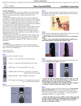
1.11 INSTALLATION
1.11.1 General
The following is a general installation process for the Test Set
STEP PROCEDURE
1. Place the Test Set on a suitable flat, clean and dry surface.
2. If the Test Set is to be mounted in an equipment cabinet, attach provided
instrument rack mountings.
3. With equipment mounted or on bench top, attach interface cables to the
appropriate RF ports.
4. For remote operation, attach GPIB cable to the Test Set and external control
computer bus.
5. Furnish electrical power to the Test Set. Connect AC power cable to rear power
input. Apply 100 to 240 VAC at 50 to 60 Hz.
1.11.2 Safety Precautions
Listed are several safety precautions which must be observed during installation and
operation. Aeroflex assumes no liability for failure to comply with any safety precautions
outlined in this manual.
Complying with Instructions
Installation/operating personnel should not attempt to install or operate the Test Set
without reading and complying with all instructions contained in this manual. All
procedures must be performed in exact sequence and manner described.
Grounding Requirements
To minimize shock hazard, all equipment chassis and cabinets must be connected to
electrical ground. All Aeroflex test sets are equipped with a standard three-prong power
cable which must be connected to a properly grounded three-prong wall receptacle.
It is the customer's responsibility to:
• Have a qualified electrician check wall receptacle(s) for proper grounding.
• Replace any standard two-prong wall receptacle(s) with properly grounded three
prong receptacle(s).
WARNING:DO NOT USE A THREE PRONG TO TWO-PRONGADAPTER PLUG. DOING SO CREATES A
SHOCKHAZARD BETWEEN THE CHASSIS AND EARTHGROUND.

General Information
Subject to Export Control, see Cover Page for details.
1 - 5
Operating Safety
Due to the presence of potentially lethal voltages within the Test Set, operating
personnel should not remove the cover with power applied.
CAUTION and WARNING Labels
Extreme care should be exercised when performing any operations preceded by a
CAUTION or WARNING label. CAUTION labels appear where possibility of damage to
equipment exists and WARNING labels denote conditions where bodily injury or death
may result.
1.11.3 Installation and Operating Precautions
CAUTION:DO NOT APPLY ANY SIGNALS TO THE TEST SET OTHER THAN THOSE DEFINED IN THE
OPERATING INSTRUCTIONS.
CAUTION: DO NOT OPERATE LCD DISPLAY WITH EXCESSIVE INTENSITY OR IN DIRECT SUNLIGHT.
CAUTION:DO NOT APPLY RF SOURCE TO RF OUT CONNECTOR.
CAUTION: TO PROVIDE MAXIMUM PROTECTION OF NON-VOLATILE INTERNAL MEMORY, DO NOT
RAPIDLY CYCLE POWER ON AND OFF. ALLOW A MINIMUM OF ONE SECOND BETWEEN ON/OFF
CYCLES.
1.12 CONTROLS, CONNECTORS AND DISPLAY
1.12.1 Front Panel Layout
Fig. 1-1 Front Panel (Left Side) Fig. 1-2 Front Panel (Right Side)

General Information
Subject to Export Control, see Cover Page for details.
1 - 6
1.12.2 Front Panel Description
1. Power Switch
Push-button (press on/off) applies power to the Test Set. Switch illuminates in the ON
position.
2. USB Port 1
Port 1 of 2 front panel universal serial bus input/output ports for remote
program loading, external keyboard or mouse.
3. USB Port 2
Port 2 of 2 front panel universal serial bus input/output ports for remote
program loading, external keyboard or mouse.
NOTE: FOR PIN-OUT DIAGRAM OF USB PORTS, REFER TO APPENDIX C.
4. Unused
5. ANT Port
Input port to the internal Test Set Digitizer resource (50 ohm).
6. T/R Port
Transmit / Receive (combiner) port of the Test Set (50 ohm).
7. GEN Port
Output port for the internal Test Set RF generator resource (50 ohm).
8. Touch Screen
Output port for the internal Test Set RF generator resource (50 ohm).

General Information
Subject to Export Control, see Cover Page for details.
1 - 8
THIS PAGE INTENTIONALLY LEFT BLANK.

Test Set Operation
Subject to Export Control, see Cover Page for details.
2 - 1
Chapter 2 - Test Set Operation
This section contains operating instructions for manual control of the Test Set.
2.1 TEST SET POWER UP
• Ensure power is applied to the Test Set. Press the POWER button to power the
Test Set On.
• For specified accuracy, allow the Test Set to warm up for 10 minutes.
NOTE: AFTER CYCLING POWER, WAIT AT LEAST 60 SECONDS BEFORE ESTABLISHING
COMMUNICATION OR MANUALLY OPERATING THE TEST SET TO ENSURE ADEQUATE TIME FOR
COMPLETING SYSTEM BOOT UP.
Fig. 2-1 Opening Screen

Test Set Operation
Subject to Export Control, see Cover Page for details.
2 - 2
2.2 TOOLBAR AND (INSTRUMENT) MENU BUTTONS
Fig. 2-2 ATS GUI Toolbar
2.2.1 Toolbar Buttons
Exit button:
Powers off the test set.
Generator-1 button:
When selected, a dropdown menu appears, providing for selection of the virtual
Generator mode (ADF, ILS LOC, ILS GS, MKR, VDB, VHF and VOR). Only one mode
may be functioning at a time for each generator card installed. If a Virtual
Instrumentation Mode has not been registered, that particular selection will be visible,
but disabled.
Analyzer-1 button (when configured with option ATB-ANL):
When selected, a dropdown menu appears, providing for selection of the virtual
Analyzer mode (DME, VHF, ELT). Only one mode may be functioning at a time.
Tools button:
When selected, a dropdown menu appears, providing for selection of GPIB Bus
Configuration and Generator Zero Calibration.
Help button:
When selected, a dropdown menu appears, providing for selection of extensive built in
documentation. This documentation can be viewed while the test set is running or
printed for future reference.

Test Set Operation
Subject to Export Control, see Cover Page for details.
2 - 3
Fig. 2-3 Help button dropdown menu
The Help buttons display documentation as follows:
Generator Help
Documentation on GENERATOR DLL modules, structures and examples.
Analyzer Help
Documentation on ANALYZER DLL modules, structures and examples.
GUI Help
This button brings up the Avionics Test Studio Software Operation Manual manual in
PDF format.
About ATS...
Registration status of the Avionics Test Studio installation
/