Page is loading ...

LOCATING THERMOSTAT
Your thermostat is a sensitive instrument. For accurate temperature
control and comfort, correct location is very important.
On new installations, the guidelines listed below should be followed as
closely as possible. When replacing an old thermostat, install the new
one in the same location unless these guidelines suggest otherwise.
1. Locate the thermostat on an inside wall about five feet off the
floor where it is easy to install, service, and adjust. It should be
in a room that is used often, such as a living room or family room.
2. Do not install it where there are unusual heating conditions, such
as in direct sunlight, or near a lamp, radio, television, radiator,
register, fireplace, or other heat producing appliance. Also,
check for hot water pipes within the wall, or a stove on other side
of wall.
3. Do not locate in unusual cooling conditions, such as on an out-
side wall, on a wall separating an unheated room, or in drafts
from stairwells, doors, or windows.
1-190D
LITHO IN U.S.A. 11/00 ©2000 Robertshaw Control Company 30965E
INSTALLATION INSTRUCTIONS
Shut off power equipment before servicing
SPECIFICATIONS
Heat anticipation range
24 volt heating. . . . . . . . . . . . . . . . . . . . . . . . . .18 to 1.0 Amps
Millivolt and 2-wire zone. . . . . . . . . . . . . . . . . . . . . . . . . . none
Cooling and 3-wire zone. . . . . . . . . . . . . . . . . . . . 4700Ω, fixed
Temperature range . . . . . . . . . . . . . . . . . . . . . . . . . . . . . 48°-65°F
except
200-403 and 503 . . . . . . . . . . . . . . . . . . . . . . . . . . . . 39°-77°F
200-405 and 505 . . . . . . . . . . . . . . . . . . . . . . . . . . . . 48°-65°F
200-406 and 506 . . . . . . . . . . . . . . . . . . . . . . . . . . . . 39°-65°F
200-605 . . . . . . . . . . . . . . . . . . . . . . . . . . . . . . . . . . . 78°-86°F
Dimensions. . . . . . . . . . . . . . . . . . . . . . . 2-13/16” rounded square
1-5/16” deep
Electrical rating
24 volt models. . . . . . . . . . . . . . . . . . . . . . . . . . . 30 VAC max.
1.0 Amp max.
Millivolt models . . . . . . . . . . . . . . . . . . . . . 250 to 750 millivolts
Differential . . . . . . . . . . . . . . . . . . . . . . . . . . . . . . . . 2°F (nominal)
Switch action . . . . . . . . . . . . . . . . . . . . . . . . . . . . . . . . . . . . SPST
except SPDT 200-901
The Energy Control Company
®
The 200 Series Thermostats are decorator designed and engineered
for outstanding performance. All models feature Uni-Line’s famous
sealed-in-glass switch which requires NO LEVELING AND OPTI-
MUM PROTECTION FROM SWITCH CONTAMINATION.
Models are available for 24 volt heating or cooling, millivolt heating,
2- or 3-wire zone, and with energy saving heating or cooling ranges.
A decorating wall plate is included with all models to cover old ther-
mostat mounting marks. (See photo at right.)
CAUTION
THIS DEVICE SHOULD BE INSTALLED BY A QUALIFIED SERVICE
TECHNICIAN WITH DUE REGARD FOR SAFETY, AS IMPROPER
INSTALLATION COULD RESULT IN A HAZARDOUS CONDITION.
IINNSSTTAALLLLAATTIIOONN DDAATTAA
200 SERIES
HEATING OR COOLING
THERMOSTATS
CONTROLS COMPANY
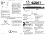
FIGURE 1
COVER
FIGURE 2
SUBBASE
FIGURE 3 - BODY

SERVICE INSTRUCTIONS—CALIBRATION
The thermostat is accurately calibrated before leaving the factory,
and no further calibration should be necessary. If however, it is nec-
essary to recalibrate the thermostat, a qualified serviceman can pro-
ceed as follows:
1. Allow the thermostat to stay in the OFF position for at least 10
minutes until the internal temperature is stabilized. During this
time the thermostat must not be influenced by heat from the
hands or any other heat source.
2. Turn the temperature selector dial indicator to the actual room
temperature measured using a reliable mercury thermometer.
3. Carefully remove the thermostat cover (noted under INSTALLATION).
4. With small crescent wrench hold dial shaft (Figure 3), being careful that
shaft does not rotate from position it was in when cover was removed.
Note: Hold wrench at angle so that steel tool does not interfere with
magnet travel.
5. Keeping hands and breath away from bimetal temperature sens-
ing element (Figure 3), turn calibration shaft in center of bimetal
coil with screwdriver counterclockwise until magnet is away from
glass switch when pressure on screwdriver is released.
6. Slowly rotate calibration shaft clockwise until magnet touches
glass switch.
7. Thermostat is in calibration. Replace thermostat cover.
Note: If magnet is away from glass switch when thermostat cover is
removed, omit step 5.
Heat Anticipation Adjustment
(Not applicable to cooling and zone models)
For average conditions, set the adjustable anticipator (upper left of
thermostat body, Figure 3) to match the current rating of the primary
heating control. Move anticipator approximately 1/2 division in direc-
tion indicated by arrows on the thermostat for longer ON cycles, or
move lever in opposite direction for shorter ON cycles. Allow at least
24 hours to determine if setting provides satisfactory operation
before making any further adjustments.
ROBERTSHAW CONTROLS COMPANY • UNI-LINE NORTH AMERICA • P.O. BOX 2000 • CORONA, CA 92879-1736
INSTALLATION INSTRUCTIONS (Cont’d)
4. Do not locate in a damp or humid area. This can shorten ther-
mostat life due to rust or corrosion.
5. Do not locate where air circulation is poor, such as in a corner,
alcove, or behind an opened door.
6. Do not install until all construction work and painting is complete.
MOUNTING THERMOSTAT
1. Remove old thermostat, if any. CAUTION: DO NOT LET WIRES
FALL BACK OUT OF REACH INTO WALL CAVITY.
2. Remove cover (Figure 1-friction fit) from thermostat body by
gripping at top and bottom and lifting from thermostat body. Use
extreme care not to damage working parts.
3. Remove subbase from the thermostat body by loosening captive
screws (see figure 3).
4. Pull approximately 3 inches of wire through the wall and thread
the wire through the center of the subbase.
5. Hold the subbase level and against the wall so that the old holes
are covered. Note: If thermostat will not cover all existing holes,
the decorative wall plate should be used during assembly. It is
not necessary to accurately level subbase, merely position for
appearance. With a pencil, mark the wall where the screws will
attach the subbase to the wall. Use designated mount'ing holes
only. Lay the subbase to one side. Drill the new mounting holes
with a 3/32” drill bit.
6. Mount decorative wall plate (if needed) and subbase to wall
using enclosed screws.
7. Connect wires to applicable terminal screws. (See schematic
diagrams below.) Push excess wire back into hole.
8. Mount thermostat body on subbase using three captive screws
(Figure 3). Captive screw in lower left hand corner of body is
selfthreading into subbase. Use care not to overtighten.
9. Replace thermostat cover being careful to align “D” shaped dial
shaft with matching shaped hole in hub of setting dial. Press
cover on to the thermostat body.
Note: Some heating and/or cooling appliances are supplied with a
time delay feature incorporated in the electrical circuit of the appli-
ance controls. If the appliance is so equipped, there may be a delay
of as much as three minutes, depending on the device used, after
the thermostat calls for heat or cooling before the appliance is actu-
ally in operation.
CAUTION
ALL WIRING MUST CONFORM TO LOCAL CODES AND ORDINANCES. DO NOT
SHORT GAS VALVE TERMINALS. THIS WILL DAMAGE WALL THERMOSTAT
AND VOID WARRANTY. A SUITABLE LIMIT CONTROL IS REQUIRED IN THE
24 VOLT OR 120 VOLT SIDE OF TRANSFORMER.
/