Page is loading ...

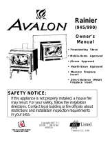
Chelan B-Vent
(700 B-Vent)
Gas Stove
and
Fireplace Insert
¥ Freestanding Stove
¥ Masonry Fireplace Insert
¥ Factory Built (Z.C.) Fireplace
Insert
Listed
WARNING: Improper installation, adjustment, alteration, service or maintenance can cause
injury or property damage. Refer to this manual. For assistance or additional
information consult a qualified installer, service agency, or the gas supplier.
- Do not store or use gasoline or other flammable vapors and liquids in the vicinity of this or
any other appliance.
- I nst al l at i on m us t be per for m ed by a qual i f ie d i ns ta l le r, s er vic e a gency or the ga s s uppl i er
IF YOU SMELL GAS
¥ Do not try to light any appliance.
¥ Do not touch any electrical switch; do not use any phone in your building.
¥ Immediatel
y
call gas supplier from a neighbor's phone. Follow the gas supplier's instructions.
¥ If you cannot reach your gas supplier, call the fire department.
- April, 1999 -
Installer: After installation give this manual
to the homeowner and explain
operation of this heater.
$10.00 93508078
10850 117th Place N.E. Kirkland, WA 98033

PAGE 2 SAFETY PRECAUTIONS
¥
IF YOU SMELL GAS:
* Do not light any appliance
* Extinguish any open flame
* Do not touch any electrical switch or plug or unplug anything
* Open windows and vacate building
* Call gas supplier from neighbor's house, if not reached, call fire
department
¥ This unit must be installed by a qualified installer to prevent the possibility of
an explosion. Your dealer will know the requirements in your area and can
inform you of those people considered qualified. The room heater should be
inspected before use and at least annually by a qualified service person. More
frequent cleaning may be required due to excessive lint from carpeting,
bedding material, etc.
¥ The instructions in this manual must be strictly adhered to. Do not use
makeshift methods or compromise in the installation. Improper installation
will void the warranty and safety listing.
THIS CONTROL
HAS BEEN
CONVERTED TO
LP
THIS CONTROL
HAS BEEN
CONVERTED FOR
NATURAL GAS
¥ This heater is either approved for natural gas
(NG) or for propane (LP). Burning the incorrect
fuel will void the warranty and safety listing and
may cause an extreme safety hazard. Direct
questions about the type of fuel used to your
dealer. Check the label on top of the gas control
valve.
Ok
¥ Contact your local
building officials to
obtain a permit and
information on any
installation restrictions or
inspection requirements
in your area. Notify your
insurance company of this
heater as well.
¥ If the flame becomes
sooty, dark orange in
color, or extremely tall,
do not operate the heater.
Call your dealer and
arrange for proper
servicing.
¥ It is imperative that
control compartments,
screens, or circulating air
passageways of the heater
be kept clean and free of
obstructions. These areas
provide the air necessary
for safe operation.
?
¥ Do not operate the heater
if it is not operating
properly in any fashion or
if you are uncertain. Call
your dealer for a full
explanation of your heater
and what to expect.
Gas
¥ Do not store or use
gasoline or other
flammable liquids in the
vicinity of this heater.
¥ Keep all furniture or other
combustible items at least
36" away from the front
of the heater.
¥ Do not operate if any
portion of the heater was
submerged in water or if
any corrosion occurs.

SAFETY PRECAUTIONS (CONTINUED) PAGE 3
¥ Do not place clothing or
other flammable items on
or near the heater.
Because this heater can be
controlled by a thermostat
there is a possibility of the
heater turning on and
igniting any items placed
on or near it.
¥ Light the heater using the
built-in piezo igniter. Do
not use matches or any
other external device to
light your heater.
¥ Never remove, replace,
modify or substitute any
part of the heater unless
¥ The viewing glass should
be opened for service
only (see the maintenance
section of this manual).
¥ Any safety screen or
guard removed for
servicing must be
replaced prior to
operating the heater.
instructions are given in
this manual. All other
work must be done by a
trained technician. Don't
modify or replace
orifices.
¥ Allow the heater to cool
before carrying out any
maintenance or cleaning.
¥ Operate the heater
according to the
instructions included in
this manual.
¥ If the main burners do not
start correctly turn the gas
off at the gas control
valve and call your dealer
for service.
¥ The pilot flame must
contact the thermopile
and thermocouple (see the
illustration to the left). If
it does not, turn the gas
control valve to "OFF"
and call your dealer.
¥ This unit is not for use
with solid fuel
¥ Do not place anything
inside the firebox (except
the included fiber logs).
¥ If the fiber logs become
damaged, replace with
Travis Industries log set.
This
Manual
¥ Do not throw this manual
away. This manual has
important operating and
maintenance instructions
that you will need at a
later time. Always follow
the instructions in this
manual.
¥ Do not touch the hot
surfaces of the heater.
Educate all children of the
danger of a high-
temperature heater.
Young children should be
supervised when they are
in the same room as the
heater.
¥ Plug the heater into a
115V grounded electrical
outlet. Do not remove the
grounding plug.
¥ Don't route the electrical
cord in front of, over, or
under the heater
¥ Instruct everyone in the
house how to shut gas off
to the appliance and at the
gas main shutoff valve.
The gas main shutoff
valve is usually next to
the gas meter or propane
tank and requires a
wrench to shut off.
¥ Travis Industries, Inc.
grants no warranty,
implied or stated, for the
installation or
maintenance of your
heater, and assumes no
responsibility of any
consequential
damage(s).

PAGE 4 TABLE OF CONTENTS
General Information
Introduction & Important Information............1
Safety Precautions ..................................2
Features & Specifications..........................5
Stove Installation
Installation Preparation .............................6
Items Required for Installation....................6
Order of Installation .................................6
Stove Clearances ....................................6
Heater Placement Requirements ................7
Floor Protection ......................................7
Gas Line Installation ................................7
Vent Requirements ..................................8
Vent Termination Requirements .................8
Electrical Connection ...............................8
Insert Installation
Installation Preparation .............................9
Items Packed with the Heater ....................9
Order of Installation .................................9
Re-Routing the Power Cord to the Front.......9
Insert Placement .....................................11
Floor Protection ......................................11
Gas Line Install .......................................12
Vent Requirements ..................................13
Vent Termination Requirements .................13
Electrical Connection ...............................13
Finalizing the Installation
1 Remove the Door..................................14
2 Install the Logs and Coals.......................14
¥ Purge the Gas Line................................14
3 Replace the Door..................................15
4 Leak Test all Gas Line Joints...................15
5 Check the Pilot Flame............................15
6 Adjust the Air Shutter.............................15
7 Check the Draft ....................................15
8 Check the Flame Height .........................15
9 Explain Heater Operation to Owner ..........15
Operating Your Heater
Before You Begin ....................................16
Location of Controls .................................16
Starting The Pilot.....................................17
Starting the Heater for the First Time ...........18
Turning the Heater On and Off ...................18
Adjusting the Flame Height........................18
Adjusting the Blower Speed.......................19
Normal Operating Sounds .........................19
Maintaining Your Heater
Maintaining Your Stove's Appearance..........20
Yearly Service Procedure..........................20
Troubleshooting
Troubleshooting Table..............................21
How this Heater Works .............................22
What Turns the Main Burners
On and Off .......................................22
What Prevents Gas Buildup.................22
Why Nothing Should Be Placed
Against the Heater.............................23
Wiring Diagram .................................23
Replacement Parts List.......................23
Warranty
Warranty................................................24
Listing Information
Safety Label ...........................................25
Optional Equipment
Stove Leg Installation ...............................26
Pedestal Installation.................................26
Telescoping Leg Installation ......................26
Surround Panel Installation........................27
Thermostat ............................................28
Remote Control Thermostat.......................29
Outside Air Kit ........................................29
Propane Conversion Kit ............................30
Index
Index ....................................................34
Symbols Used in this Manual
Requirement
¥1!?+
Hint
NoteWarningStep

FEATURES AND SPECIFICATIONS PAGE 5
Installation Options:
¥ Freestanding
¥ Masonry Fireplace Insert
¥ Zero-Clearance (Metal)
Fireplace Insert
Features:
¥ Works During Power Outages
(millivolt system)
¥ High Efficiency; Up to 80% for Natural Gas,
82% for LP (Steady State)
¥ Optional Thermostat or Remote Control
¥ Realistic "Wood Fire" Look
¥ Convenient Operating Controls
¥ Variable-Rate Heat Output
¥ Quiet Blower for Effective Heat Distribution
¥ Low Maintenance
Heating Specifications:
Approximate Heating Capacity (in square feet)* 600 - 1600
AFUE (Annual Fuel Utilization Efficiency) 68 %
Natural Gas LP (Propane)
High Burn Input Rate (In BTU's) 40,000 38,000
Low Burn Input Rate (In BTU's) 23,000 20,000
Efficiency** 80% 82%
* Heating capacity will vary with the home's floor plan and insulation, natural gas or Propane BTU rating, and outside temperature.
** Efficiency rating is a product of thermal efficiency rating determined under continuous operation independent of installed system.
To measure the net BTU's, multiply the BTU input by the efficiency percentage (80% for natural gas, 82% for LP).
Dimensions
20-1/8"
8" Panels: 28"*
10" Panels: 30"*
12" Panels: 32"*
13"*
5-3/4"*
* Includes
i
23-3/4"
8" Panels: 40"*
10" Panels: 44"*
12" Panels: 48"*
18-5/8"
23-3/4"
Pedestal: 31-1/2"
Brass, Cast Legs: 28"
Black Legs: 26-5/8"
Weight: 175 Lbs.
Measure Clearances
from the Upper Top
The base of the
starter section
is 2" below the
upper top.
4-1/2"
4-1/2"
The base of the starter section
is 2" below the upper top.
Fuel:
The heater is designed either for natural gas or for propane (but not
for both). Check the sticker on the top of the gas control valve.
Emissions:
This unit has passed the ANSI emission standards for vented room
heaters as tested by OMNI Environmental Services, Inc.
Electrical Specifications:
115 Volts, 1.3 Amps, 60 Hz (150 watts on high)

PAGE 6 STOVE INSTALLATION - For qualified installers only!
Installation Preparation
! This appliance must be installed in accordance with all local codes, if any; if not, follow ANSI
Z223.1 and the requirements listed in this manual. Failure to follow all of the requirements
may result in property damage, bodily injury, or even death.
! Notify your insurance company before hooking up this heater.
! The requirements listed below are divided into sections. All requirements must be met
simultaneously. The order of installation is not rigid Ð the qualified installer should follow the
procedure best suited for the installation.
Items Required for Installation
¥ B-Vent System
¥ Brass, Black, or Cast Legs or Pedestal
¥ Gas Hookup Equipment
Items Packed with the
Chelan (700) B-Vent
¥ Gas Inlet (3/8" Pipe)
¥ Propane Conversion Kit
¥ Owner's Manual
¥ Log Set (2 Logs, 2 Twigs, Embers)
¥ 2 Leveling Bolts (3/8"-16 x 3" Carriage Bolts - not used for stove installations)
Order of Installation
1 Attach the legs or pedestal (see page 26)
2 If the heater is to use propane, install the propane conversion kit (see page 31)
3 Position the heater, use floor protection if needed
4 Attach any optional equipment.
5 Connect the gas line. Connect the gas vent.
6 Follow the instructions under "Finalizing the Installation" on pages 14 and 15.
Stove Clearances
10" Min.
4" Min.
45¡
Straight Installations Corner Installations
When installed with this clearance, the
vent is 13-1/2" from the wall.
4" Min.
When installed with
this clearance, the
vent is 6-1/4" from the
back wall, 19-1/2"
from the side wall.

STOVE INSTALLATION (CONT.) - For qualified installers only! PAGE 7
Heater Placement Requirements
¥ Heater must be installed on a level surface capable of supporting the heater and vent
¥ Due to the high temperature of the heater, it should be located out of traffic and away from furniture and draperies.
Heater must be placed so no combustibles are within, or can swing within 36" of the front of the heater (e.g. drapes,
doors)
? When placed in a location where the floor to ceiling height is under 7 feet , the installation is considered an alcove and
must meet the following requirements:
¥ The alcove floor to ceiling height must be at least 58" tall
¥ The alcove must not be more than 45" deep (before the ceiling returns to 7 feet)
¥ The alcove must be at least 44" wide
¥ The heater must not be placed so the vents below or above the door, along the sides of heater, or along the back of the
heater can become blocked.
Floor Protection
¥ When the stove is installed directly on carpeting, vinyl or other combustible material other than wood flooring or a high
pressure laminate wood floor, the stove must be installed on a metal or wood protection panel extending the full width
and depth of the heater (Minimum 23-3/4" wide by 18-5/8" deep).
Gas Line Installation
! The gas line must be installed in accordance with all local codes, if any; if not, follow ANSI Z223.1 and the requirements
listed below.
Rear
Panel
Gas Inlet
(3/8" diameter pipe)
NOTE:
Apply thread
sealant prior to
installing.
Use a pipe wrench
to tighten in place.
12-7/8" Pedestal
9-1/2" Brass/Cast Legs
8" Steel Legs
1-1/2"
7-1/2"
Center of
Stove
! The heater and gas control valve must be disconnected from the gas supply piping during any pressure testing of that
system at test pressures in excess of 1/2 psig. For pressures under 1/2 psig, isolate the gas supply piping by closing the
manual shutoff valve.
¥ This heater is designed for natural gas but can be converted to propane. Check the sticker on the top of the gas control
valve to make sure the correct fuel is used.
¥ Leak test all gas line joints and the gas control valve prior to and after starting the heater.
¥ The gas inlet accepts a 3/8" F.P.T. fitting
¥ The location of the gas inlet is shown below
¥ A manual shutoff valve is required for installation (it must be located within 3' of the heater)
Gas Inlet Pressure
¥ With the heater off, the inlet pressure must meet the requirements listed in the table below
? If the pressure is not sufficient, make sure the piping used is large enough and the total gas load for the residence does
not exceed the amount supplied.
? The supply regulator (the regulator that attaches directly to the residence inlet or to the propane tank) should supply gas
at the suggested input pressure listed below. Contact the local gas supplier if the regulator is at an improper pressure.
Standard Input Pressure
Natural Gas 7" W.C.
Propane 11" W.C.

PAGE 8 STOVE INSTALLATION (CONT.) - For qualified installers only!
Vent Requirements
! Always maintain the required 1" clearance (air space) to combustible materials to prevent a fire
hazard. Do not fill air spaces with insulation.
! The gas appliance and vent system must be vented directly to the outside of the building, and never
be attached to a chimney serving a separate solid fuel or gas-burning appliance.
¥ Minimum 5' vertical rise
from top of stove (see
the illustration below)
¥ When the vent passes
through a wall, a wall
thimble is required.
When the vent passes
through a ceiling, a
support box or firestop is
required. When the vent
passes through the roof,
a roof flashing and storm
collar are required.
Follow the instructions
and requirements
provided with the vent
when installing.
¥ The horizontal run may
not exceed 50% of the
vertical rise
Type B Vent
Vent must
terminate a
minimum 1'
above the roof.
Listed Gas
Chimney Liner
Maintain 1"
minimum
clearance
Provide a 1/4" rise
for every 12" run.
Min. 5' Rise
High
temperature
factory built
chimney and
connector
Chimney with LinerStandard Installation Exterior Vent
Min. 5' Rise
The total
horizontal
run must
not exceed
50% of the
vertical rise
Do not block gas
vent termination
¥ Use 4" dia. B vent for entire system from one manufacturer (don't mix brands)
- or -
Use high temperature factory built or masonry chimney with listed gas chimney liner running the
entire length
¥ Vent termination must be above the roof and not below any eaves or overhangs
Drafting
Performance
This appliance relies upon natural draft to operate. External forces, such as wind,
barometric pressure, topography, or factors of the home (negative pressure from
exhaust fans, chimneys, air infiltration, etc.), may adversely affect draft. Travis
Industries can not be responsible for external forces leading to less than optimal
performance.
Vent Termination Requirements
¥ Vent termination must have an approved cap (to prevent water from entering)
¥ Vent termination must not be located where it will become plugged by snow or other material
¥ Vent termination must be
1' above the roof and
meet the requirements
outlined in ANSI
Z223.1, section 7.6.2.
12Ó Min.
Note: ANSI 223.1, section 7.6.2 outlines additional
requirements for gas vent terminations. If your
installation involves a roof with a slope greater
than 6/12 or if a wall or other vertical obstruction is
within 8' of the vent termination, the vent
termination will need to be taller. Refer to ANSI
223.1 for full details.
! When installed, the vent must provide suitable draft for the appliance. Other factors, such as exhaust
fans, may create negative pressure inside the home and cause down drafts. Additional vent height
may be required in these circumstances.
Electrical Connection
¥ Plug the power cord into a grounded 110 Volt outlet (do not remove the grounding plug).

INSERT INSTALLATION - For qualified installers only! PAGE 9
Installation Preparation
! This appliance must be installed in accordance with all local codes, if any; if not, follow
ANSI Z223.1 and the requirements listed in this manual. Failure to follow all of the
requirements may result in property damage, bodily injury, or even death.
! Notify your insurance company before hooking up this heater.
! The requirements listed below are divided into sections. All requirements must be met
simultaneously. The order of installation is not rigid Ð the qualified installer should follow
the procedure best suited for the installation.
Items Packed with the Heater
¥ Propane Conversion Kit
¥ Owner's Manual
¥ Log Set (2 Logs, 2 Twigs, Embers)
¥ Gas Inlet (3/8" Pipe)
¥ 2 Leveling Bolts (3/8"-16 x 3" Carriage Bolts - used to level the heater in fireplaces with stepped-up hearths)
Order of Installation
1 If the heater is to use propane, install the propane conversion kit (see page 31)
2 Connect the gas inlet (see page 12)
3 Re-route the power cord (if desired - see below)
4 Position the heater (see "Heater Placement")
5 Connect the gas line. Connect the gas vent.
6 Follow the instructions under "Finalizing the Installation" on pages 14 and 15.
7 Install the surround panel kit.
Re-Routing the Power Cord to the Front
The power cord may be re-routed to the front of the heater if desired (see the directions below).
1 Disconnect the strain relief at the rear of the heater.
Strain Relief
Power Cord
Compress the strain relief
from the top and bottom
with a pair of slip joint
pliers. Once compressed,
the strain relief can be
pulled out.
TO REMOVE THE STRAIN RELIEF
Compress the strain relief
from the top and bottom
and insert it into the hole
until it locks in place.
TO INSTALL THE
STRAIN RELIEF

PAGE 10 INSERT INSTALLATION (CONT.) - For qualified installers only!
Re-Routing the Power Cord to the Front (continued)
2 Carefully pull on the power cord until the molex connector is exposed. Disconnect the molex
connector.
Molex Connectors
Power Cord
Wires Leading
from the Heater
3 Pry out one of the button plugs on either side of the insert (see the illustration below).
4 Open the control cover and locate the wires leading from the power cord molex connector (green,
white, and black wires). Pull these wires forward. Insert the molex connector on the power cord
through the hole exposed in step 2 and re-connect to the molex connector on the heater. Tuck any
excess wire underneath the clip on the baseplate to prevent any wires from contacting the burner
pan.
Button Plug
(found on both sides)
Remove the button
plug by prying it loose
with a screwdriver
The power cord must
be routed underneath
this clip to prevent it
from touching the
bottom of the burner
pan.
Standard
Screwdriver
5 Secure the power cord to the heater with the strain relief (see the illustration under step 1).

INSERT INSTALLATION (CONT.) - For qualified installers only! PAGE 11
Insert Placement
The Insert Must be
Placed 13" into the
Fireplace.
Run the power cord to
either side of the insert
along the facing.
The insert must be in place with
the gas line and vent attached
prior to installing the panels.
Min. 29-3/4" WIde (includes 6" for gas
line installation)
Min. 22-1/8" Tall
(includes 2" for
vent installation)
See the section "Gas Line
Installation" for details on the
location of the gas inlet.
Use the leveling bolts for
fireplaces with recessed
floors (included with the
stove).
¥ Insert must be placed so no combustibles are within, or
can swing within 36" of the front of the heater (e.g.
drapes, doors)
¥ The insert may be placed inside a masonry fireplace or
listed zero-clearance (metal) fireplace
¥ The insert must be installed in a level, undamaged
fireplace (damage must be repaired prior to
installation). Use the included leveling bolts to level
the insert in fireplaces with recessed floors.
¥ The insert must maintain 10" clearance to sidewalls
(measure from the upper top)
¥ Non-combustible facing (e.g. brick, tile) must extend 8"
minimum from the side and 8" to the top of the insert
(measure from the upper top)
¥ Combustible mantles must be a minimum 17-1/2"
above the top of the insert (measure from the upper top)
Floor Protection
¥ The heater must be installed on a non-combustible
hearth and may not extend over combustible flooring
Zero-Clearance (Metal)
Fireplace Requirements:
¥ The damper ("A") and grate (with logset)
("B") must be removed (see the illustration
below)
¥ The smoke shelf ("C"), internal baffles
("D"), screen ("E"), masonry lining or
refractory ("G" & "I"), and metal or glass
doors ("F") may be removed (if applicable)
¥ The insulation ("H"), and any structured
rigid frame members (metal sides, floor,
door frame, face of the fireplace, etc.) may
not be removed or altered.
C
B
F
I
D
E
A
G
H

PAGE 12 INSERT INSTALLATION (CONT.) - For qualified installers only!
Gas Line Install
! The gas line must be installed in accordance with all local codes, if any; if not, follow ANSI Z223.1
and the requirements listed below.
! The heater and gas control valve must be disconnected from the gas supply piping during any
pressure testing of that system at test pressures in excess of 1/2 psig. For pressures under 1/2 psig,
isolate the gas supply piping by closing the manual shutoff valve.
¥ Leak test all gas line joints and the gas control valve prior to and after starting the heater.
Gas Line Connection
¥ The gas inlet accepts a 3/8" F.P.T. fitting
¥ The location of the gas inlet is shown below
¥ A manual shutoff valve is required for installation (it must be located within 3' of the heater)
Rear
Panel
Gas Inlet
(3/8" diameter pipe)
NOTE:
Apply thread
sealant prior to
installing.
Use a pipe wrench
to tighten in place.
1-1/2"
7-1/2"
Center of
Stove
1-5/8"
Fuel
¥ This heater is designed for natural gas but can be converted to propane (see page 31). Check the
sticker on the top of the gas control valve to make sure the correct fuel is used.
Gas Inlet Pressure
¥ With the heater off, the inlet pressure must meet the requirements listed in the table below
? If the pressure is not sufficient, make sure the piping used is large enough and the total gas load for
the residence does not exceed the amount supplied.
? The supply regulator (the regulator that attaches directly to the residence inlet or to the propane tank)
should supply gas at the suggested input pressure listed below. Contact the local gas supplier if the
regulator is at an improper pressure.
Minimum Input Pressure
Natural Gas 5.5" W.C.
Propane 11" W.C.

INSERT INSTALLATION (CONT.) - For qualified installers only! PAGE 13
Vent Requirements
! Always maintain the required 1" clearance to combustible materials to prevent a fire hazard.
! The gas appliance and vent system must be vented directly to the outside of the building, and never
be attached to a chimney serving a separate solid fuel or gas-burning appliance.
¥ The vent must reline the entire length of the chimney and have a minimum 5' vertical rise
¥ Horizontal run may not exceed 50% of the vertical rise
¥ Use 4" listed gas chimney liner or B vent from one manufacturer (don't mix brands)
? When using flexible gas vent, do not crimp or rupture the liner when bending it into chimney offsets
¥ When installed, the vent must meet all of the vent manufacturer's requirements
? When installed, the vent must provide suitable draft for the appliance. Other factors, such as exhaust
fans, may create negative pressure inside the home and cause down drafts. Additional vent height
may be required in these circumstances.
4" Listed gas chimney
liner or B Vent
Hearth and/or hearth
pad must extend
underneath insert
Z.C. (Metal)
firebox
6"
Min.
A sealed cover plate
is recommended, but
not required.
Surround
Panel
(Do not seal)
17-1/2"
Min.
6"
Min.
Leveling bolts for step-up hearths
Zero
Clearance
Fireplace
Surround Panel
(Do not seal)
Approved Cap
Masonry
Fireplace
17-1/2"
Min.
We recommend sealing this
area to prevent heat loss.
Use the
telescoping
legs for
raised
fireplaces.
Drafting
Performance
This appliance relies upon natural draft to operate. External forces, such as wind,
barometric pressure, topography, or factors of the home (negative pressure from
exhaust fans, chimneys, air infiltration, etc.), may adversely affect draft. Travis
Industries can not be responsible for external forces leading to less than optimal
performance.
Vent Termination Requirements
¥ Vent termination must have an approved cap (to prevent water from entering)
¥ Vent termination must not be located where it will become plugged by snow or other material
¥ Vent termination must extend a minimum of 6" above the top of the chimney
Electrical Connection
¥ Plug the power cord into a grounded 110 Volt outlet (do not remove the grounding plug).

PAGE 14 FINALIZING THE INSTALLATION
! Turn the gas control valve to "OFF" prior to conducting any service.
1 Remove
the door.
Unscrew and remove the door handle.
NOTE: When re-installing, make sure the handle points away from the glass when finished.
Swing the door until it is open 90¡ Lift the door up and away from the heater.
2 Install the
logs,
twigs, and
embers.
Rear Log (largest)
Front Log
Burner Pan
The rear log has a
flat portion that
rests on this ledge.
The front log rests on
these platforms.
These clips keep the rear log
from tilting backwards.
Log Installation
Twig
Installation
Slide the front log all the way
back against the air deflector.
The rear log
protrudes over the
burner pan on both
sides.
The front edge of
the front log rests
on this ledge.
The rear log contacts
the air deflectors.
Align the holes
in the left twig
over the pegs
on the front and
back logs.
Ember
Installation
Place the embers on this ledge at the
front of the firebox . Do not place the
embers over the burner holes.
Align the holes
in the right twig
over the pegs
on the left twig
and back log.
! We recommend you purge the gas line at this time (with the glass removed). This allows gas to be
detected once it enters the firebox, ensuring gas does not build up.

FINALIZING THE INSTALLATION (CONT.) PAGE 15
3 Replace the door (follow step # 1 in reverse order).
4 Turn on gas to the
heater. Leak test all
gas joints prior to
starting the
appliance. Start the
pilot. Start the main
burner. Leak test all
gas joints again.
5 Check the pilot flame
to make sure it looks
like the illustration to
the right. Adjust the
pilot flame if
necessary.
6 Let the heater burn
for fifteen minutes.
Adjust the air shutter,
if necessary, to
achieve the correct
looking flame (see
the illustration to the
right).
¥ The air shutter
adjusts the amount of
air that mixes with
the gas before it exits
the burner holes. It
is used to fine-tune
the flame for
differences in
altitude and vent
configuration.
The pilot flame should impinge the top 3/8Ó (10 mm)
of the thermopile. If it does not, you may need to
turn the pilot up.
3/8Ó (10 mm)
Thermopile
Pilot Hood
Thermocouple
To adjust the pilot flame, remove the cover screw (and
gasket) and turn the needle valve. Clockwise lowers
the flame while counter-clockwise raises it.
PILOT ADJ
T
O
L
P
I
ON
OFF
Standard
Screwdriver
Micro (1/16Ó)
Standard
Screwdriver
The cover screw and
gasket must be
replaced to prevent gas
from leaking
Cover Screw
Cover Screw Gasket
Needle Valve
Gas Control Valve
PILOT ADJ
VENT
HI
LO
Correct
Flames should be blue at the
base, yellow-orange on the top.
If the flames are too tall or sooty on
the ends, push up on the lever.
If the flames are all blue and
short, pull down the lever.
Not Enough Air Too Much Air
Locate the air shutter adjustment
lever behind the gas control valve.
Move it up or down until the flame
looks correct. Pushing up gives the
flame more air (making it bluer).
Pulling it down cuts air down,
making it more orange.
NOTE: If the air control is all the
way up, yet the flames remain
sooty, shut off gas to the fireplace
and contact a qualified gas service
technician.
NOTE: The logs must be installed correctly to
monitor the flame while adjusting the air shutter.
T
O
L
P
I
ON
OFF
! If the air shutter is in its fully open position, yet the flames remain sooty, shut off gas to the heater
and contact your dealer for a remedy.
7 Ensure the heater establishes a draft. If the heater unexpectedly shuts off 5 to 25 minutes after
starting, the heater may not be drafting. The cause: negative pressure. Typically, re-starting the
heater five minutes after the shutoff will overcome the negative pressure and establish a draft.
However, if this does not work, you may wish to open a door or window near the heater. This will
allow in enough air in to overcome any negative pressure. Once drafting is initiated, the heater will
work properly without having to re-start the heater or allow in outside air. This is due to the heat
generated by the pilot.
Possible Causes of Negative Pressure:
¥ Exhaust fans (Jenn-Aire type fans in kitchens, bathroom fans)
¥ Vent termination located near a down draft or against prevailing winds
¥ Internal home pressure characteristics (multiple fireplaces, etc...)
8 Turn the flame adjust knob to its highest position - the flames should be approximately 10" tall.
Check the flame on low position. The flames should burn off of each burner hole. If the heater does
not work correctly, contact your dealer for a remedy.
9 Give this manual to the home owner and fully explain the operation of this heater.

PAGE 16 OPERATING YOUR HEATER
Before You Begin
! Read this entire manual before you use your new heater (especially the section "Safety
Precautions" on pages 2 & 3). Failure to follow the instructions may result in property
damage, bodily injury, or even death.
Location of Controls - See explanation below
Swing the control cover to the
right to access the gas control
valve, igniter, and blower control.
Gas
Control
Valve
PILOT ADJ
VENT
T
O
L
P
I
ON
OFF
HI
LO
Gas Control
Knob
Flame Adjust
Knob
Blower Knob
BLOWER
LO
OFF
HI
PILOT
IGNITER
Pilot Igniter
ON/OFF
Switch
The on/off switch
is located on the
right side of the
control cover.
The Pilot Flame can be
found below the back log
on the left side.
O
F
O
N
F
Blower Knob This knob controls the speed of the internal convection blower that pushes the
heated air into the room.
On/Off Switch This control is used to turn the heater on and off.
Pilot Igniter The pilot igniter is used only to start the pilot. When pressed, it sends an
electrical charge to the pilot assembly. This creates a blue spark directly next
to the pilot, igniting the pilot flame.
Gas Control Knob This knob is used to control gas to the heater and for starting the pilot. There
are three positions, ON, OFF, & PILOT. The pointer directly below the knob
indicates the position this knob is in.
Flame Adjust Knob This knob controls the flame height from low ("LO") to high ("HI"). The
pointer to the upper right of the knob points to the position this knob is in.
? If using a remote control or thermostat, the On/Off Switch must be left "ON". Turning the On/Off
Switch "OFF" will keep the heater off always.

OPERATING YOUR HEATER (CONTINUED) PAGE 17
Starting
The Pilot Flame
The pilot flame is required to ignite the main burners (it also plays a safety role). It should be
left on once lit. It will stay lit unless the gas control valve is turned to "OFF". However, the
pilot will go out if the gas is shut off or if the stove malfunctions. If the pilot turns off
frequently, call your dealer for information. To start the pilot follow the directions below:
NOTE: IF YOU'RE TRYING TO RE-LIGHT THE PILOT BECAUSE SERVICE WAS
PERFORMED ON THE UNIT (I.E. GAS LINE REMOVED THEN RE-INSTALLED OR
BECAUSE TANK RAN OUT OF GAS), FOLLOW THE INSTRUCTIONS FOR REMOVING
THE DOOR ON PAGE 14 THEN BLEED THE GAS LINE.
A Push the gas control knob in
slightly and turn it to the
"OFF" position. The knob
will not turn from "ON" to
"OFF" unless the knob is
depressed slightly.
B Wait five minutes to let any
gas that may have
accumulated inside the
firebox escape. If you smell
gas, follow the directions on
the cover "IF YOU SMELL
GAS".
C Turn the gas control knob to
the "PILOT" position and
press the knob in, this will
allow gas to flow to the pilot
light. Press the red button
on the pilot igniter
repeatedly until you see the
pilot light. KEEP THE GAS
CONTROL KNOB
DEPRESSED FOR 30
SECONDS ONCE IT IS
LIT. NOTE: IF THE
PILOT DOES NOT
LIGHT AFTER 15
SECONDS, RELEASE
THE KNOB AND CALL
YOUR DEALER FOR
SERVICE.
D Release the gas control
knob. If the pilot goes out,
repeat step C. If the pilot
refuses to stay lit, call your
dealer for service.
E Turn the gas control knob
counter-clockwise to "ON".
The pilot is now lit and the
stove can be turned on and
off.
PILOT ADJ
PILOT ADJ
PILOT
IGNITER
T
O
L
P
I
ON
OFF
PILOT ADJ
T
O
L
P
I
ON
OFF
30 seconds
5 minutes
T
O
L
P
I
ON
OFF
PILOT ADJ
T
O
L
P
I
ON
OFF
?
AB
C
D
PILOT ADJ
E
T
O
L
P
I
ON
OFF
Do not press knob in for more than
15 seconds if pilot does not light.
Call Your Dealer For Service

PAGE 18 OPERATING YOUR HEATER (CONTINUED)
Starting the Heater for the First Time
¥ Painted Stoves require the paint to be cured. Start the heater and burn on low for 20 minutes. Turn
off and let cool. Repeat twice to fully cure the paint.
+ Fumes and smoke from the paint curing and oil burning off the steel may occur the first time you
start your heater. This is normal. We recommend you open windows to vent the room.
+ Condensation may appear on the glass each time you start the heater - this is normal.
+ Blue Flames will occur on the heater when it first comes on. After fifteen minutes the flames will
turn a more realistic yellow and orange color.
? Certain installations use a remote "wall switch" to turn the heater on and off. If this is the case, leave
the ON/OFF switch "ON".
Turning the Heater On and Off
O
F
F
O
N
Use this switch to
turn the main burner
on and off manually.
After the pilot has been started...
See the instructions included
with the remote for details on
operation.
For systems with thermostats,
use this switch to control the
temperature (right is hotter, left
cooler). Some systems
require the on/off switch to be
on.
See the instructions
included with the
remote for changing
the battery.
! Do not place any combustible items on top of or directly in front of the heater, even temporarily.
The optional thermostat may start the heater causing a combustible item to ignite.
? If the heater turns on and off frequently while using the thermostat, you may want to adjust the flame
height down until it produces just enough heat needed.
Adjusting the Flame Height
+ Your heater has an adjustable flame to tailor the look and heat output to your specific needs. It is
adjusted by turning the middle dial on the gas control valve.
Flame Height
Adjustment Knob
Index Mark
Turn clockwise to adjust the flame higher, counter-clockwise to lower.
PILOT ADJ
VENT
T
O
L
P
I
ON
OFF
HI
LO
VENT
HI
LO

OPERATING YOUR HEATER (CONTINUED) PAGE 19
Adjusting the Blower Speed
+ The blower helps transfer the heat from the heater into the room. It will not turn on until the heater
is up to temperature (approximately 10 minutes after starting). See the illustration below for
instructions on adjusting the blower speed.
BLOWER
LO
OFF
HI
PILOT
IGNITER
Blower Knob
Turn the knob all the way counter-clockwise to turn
the blower off. One click clockwise turns the
blower to high speed. Turning the knob clockwise
from the high position decreases the speed of the
blower.
Normal Operating Sounds
Gas Control Valve
As the gas control
valve is turned on
and off you will hear
a dull clicking
sound. This is the
valve opening up
and shutting down.
Blower Snap Disk
This part can
produce a clicking
sound as it turns the
blower on and off.
The appliance may
creak with change of
temperature.
Pilot Flame
The pilot flame,
which remains on,
makes a very slight
"whisper" sound.
Blower
This heater uses a blower to push
heated air into the room. You will hear
the sound of air movement that
increases as the speed is increased.

PAGE 20 MAINTAINING YOUR HEATER
Maintaining Your Stove's Appearance
! The optional brass door may be cleaned with a non-abrasive polish (such as Flitz¨). The brass trim
is anodized and should not be polished.
Yearly Service Procedure
! Failure to inspect and maintain the heater may lead to improper combustion and a potentially
dangerous situation. We recommend the following procedures be done by a qualified technician.
1 Check the pilot flame. It should engulf approximately 3/8" of the top of the thermocouple (see
illustration below). If it does not, contact your dealer for service.
2 Shut off gas to the heater by turning the gas control knob to "OFF" (see step A under "Starting the
Pilot" on page 17). Let the heater cool for 15 minutes. Remove the door (see step 1 on page 14).
3 Remove the logs, twigs and coals (see page 14 - NOTE: the logs are fragile). If any log is cracked
or deteriorated, replace it when re-installing. Check the logs for sooting. A small amount of soot
along the bottom of the logs is normal. If excessive sooting is found, the heater will require
adjustment. Contact your dealer.
4 Clean the burner pan (especially in the burner holes and slots) and inspect the following:
¥ Check for burner pan holes that are cracked, severely warped, or corroded.
¥ Make sure the burner pan assembly fits flat against the floor of the firebox.
¥ Check the firebox and area around the pilot to make sure there is no warping or damage.
If any problem is found, discontinue use and contact your dealer for service.
Check the burner
holes and slots.
Make sure the
burner pan seals
against the floor
of the firebox.
Check the walls and
ceiling of the firebox
for deterioration.
Burner Pan
Before Disassembly: Check the pilot flame. It should
impinge the top 3/8Ó of the thermopile and engulf the
thermocouple.
3/8Ó
Thermopile
Pilot Hood
Thermocouple
5 Replace the log set. Inspect the door gasket. If it is deteriorated, replace. It may be re-attached to
the door using high-temperature gasket cement. If the glass is damaged, replace it. Replace the
door. Make sure the gasket forms a seal.
6 Inspect the area behind the control cover. Check the gas control valve and all of the gas lines. If any
damage is found, discontinue use and contact your dealer for service.
7 Start the pilot and turn on the main burner. The flames should be orange/yellow and not touch the
top of the firebox. If the pilot or main burners do not burn correctly, contact your dealer for service.
Monitor the blower operation.
8 Remove any debris or vegetation near the vent termination. Contact your dealer if any sooting or
deterioration is found near the vent termination.
/