

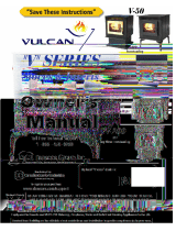
Canadian Comfort Industries V05 2 VULCAN “V” SERIES OWNERS MANUAL
Copyright 2005
www.salesunlimited.com Dansons Group Inc.
Dear VULCAN “V” SERIES Pellet Stove Owner:
CONGRATULATIONS on the purchase of your VULCAN “V” SERIES wood pellet appliance! You have selected
the finest in residential wood pellet heating technology.
Let us pass on a few "tips" concerning installing your stove and heating with wood pellets.
1. Whether you install your stove yourself or hire a professional installer, a quality installation
is a must for the safety of your family and for efficient, satisfactory operation of your stove.
2. Initial Burn Setup of the stove is the most important step to ensure the efficient and satisfactory
operation of your appliance for many years to come.
3. Know the quality and characteristics of the pellets you burn. Pellets can vary greatly from
company to company, from load to load and occasionally from bag to bag.
4. Be extra diligent in your cleaning program.
5. Remember that most operational dilemmas with a pellet stove are usually traced back to
Improper installation, poor quality pellets and/or a lack of timely cleaning.
With just a minimum of daily care your VULCAN “V” SERIES pellet appliance will provide years of clean, efficient,
comfortable and environmentally sound heating.
Thank you for selecting a VULCAN “V” SERIES wood pellet appliance.
Sincerely,

Can
adian Comfort Industries V05 3 VULCAN “V” SERIES OWNERS MANUAL
Copyright 2005
www.salesunlimited.com Dansons Group Inc.
TABLE OF CONTENTS
GENERAL INFORMATION
SAFETY PRECAUTIONS ----------------------------------------------------------------------
4,5
SAFETY TESTING ----------------------------------------------------------------------
5
HOW YOUR VULCAN “V” SERIES STOVE WORKS ----------------------------------
6
AUTOMATIC SAFETY FEATURES -----------------------------------------------------------
7
SPECIFICATIONS ------------------------------------------------------------------------------
8
INSTALLATION
INSTALLATION PLANNING & CHECK LISTS ------------------------------------------
9
INSTALLATION OPTIONS -------------------------------------------------------------------
10
EXHAUST SYSTEMS ---------------------------------------------------------------------------
11
SIZING ------------------------------------------------------------------------------------------
11
TERMINATION -------------------------------------------------------------------------------
12
CLEARANCES --------------------------------------------------------------------------------
12
OUTSIDE AIR -------------------------------------------------------------------------------------
13
FREESTANDING INSTALLATION
STOVE PLACEMENT -----------------------------------------------------------------------
14
FLOOR PROTECTION ----------------------------------------------------------------------
14
CLEARANCES -------------------------------------------------------------------------------
14
ALCOVE ----------------------------------------------------------------------------------------
15
THROUGH THE WALL DIRECT INSTALLATION ----------------------------------
16
VERTICAL INSTALLATIONS -------------------------------------------------------------
17
MOBILE HOME INSTALLATION -------------------------------------------------------------
18
INSERT / BUILT-IN INSTALLATION
IN A WOOD OR COAL BURNING FIREPLACE -------------------------------------
19
IN A WALL OR MANTEL -------------------------------------------------------------------
21
OPERATION
LIGHTING A FIRE -------------------------------------------------------------------------------
23
THE ACUTRON CONTROLS -----------------------------------------------------------------
24
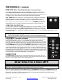
SHUTTING THE STOVE OFF ----------------------------------------------------------------
25
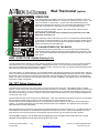
ACUTRON WALL THERMOSTAT (OPTIONAL) ----------------------------------------
26
INITIAL BURN SETUP --------------------------------------------------------------------------
27
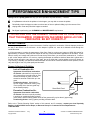
PERFORMANCE ENHANCEMENT TIPS -------------------------------------------------
28
PELLETS
PELLET QUALITY ------------------------------------------------------------------------------
29
PELLET CONSUMPTION ---------------------------------------------------------------------
29
FACTORS EFFECTING PELLET FEED RATES ---------------------------------------
29
FINE TUNING THE PELLET FEED RATES ----------------------------------------------
29
ASH and CLINKERS ---------------------------------------------------------------------------
30
FINES ---------------------------------------------------------------------------------------------
30
PFI PELLET STANDARDS -------------------------------------------------------------------
30
MAINTENANCE
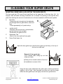
INSERTING, REMOVING, AND ADJUSTING THE BURN GRATE ----------------
31
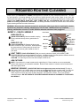
REQUIRED CLEANING ------------------------------------------------------------------------
32
PERIODIC MAINTENANCE -------------------------------------------------------------------
33
TROUBLE SHOOTING -------------------------------------------------------------------------
35
LIMITED WARRANTY -------------------------------------------------------------------------
36
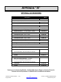
APPENDIX “A” - VULCAN “V” SERIES OPTIONS ------------------------------
37
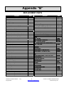
APPENDIX “B” – VULCAN “V” SERIES ACCESSORIES ---------------------
38
SERVICE LOG ----------------------------------------------------------------------------
40

Can
adian Comfort Industries V05 4 VULCAN “V” SERIES OWNERS MANUAL
Copyright 2005
www.salesunlimited.com Dansons Group Inc.
SAFETY PRECAUTIONS
IMPORTANT: Read, save and follow the instructions in this manual. It contains important Safety,
Operating and Maintenance instructions you will need.
• BEFORE installing or having the pellet appliance installed contact the local building officials to obtain the
necessary permits and information on any installation restrictions or inspection requirements in your area
and notify your insurance company you have installed a pellet appliance.
• This unit must be properly installed to prevent the possibility of a house fire. The instructions and local
building codes requirements must be strictly adhered to. Do not; use makeshift methods or material that
may compromise the installation.
• When the pellet appliance is installed in a mobile home, the heater must be bolted to the floor, have outside
air, and MUST NOT BE INSTALLED IN THE BEDROOM (Per H.U.D. requirements). Check with local
building officials.
• NEVER try to repair or replace any part of the heater unless instructions for consumer are given in this
manual or instructed by Dansons Customer Service Department. A trained technician should do all other
work.
• Educate all children of the danger of a high-temperature heater. Young children should be supervised
when they are in the same room as the heater.
• This heater is designed and approved for pelletized wood fuel only. Any other type of fuel burned in this
heater will void the warranty and safety listing. Keep foreign objects out of the hopper.
• NEVER use gasoline, gasoline-type lantern fuel, kerosene, charcoal lighter fluid, or similar liquids to start or
“freshen up” a fire in this appliance. Keep all such liquids well away from the appliance while it is in use.
• This heater must be connected to a standard 115 V., 60 Hz grounded electrical outlet. A grounded surge-
protection unit is recommended.
• Do not use an adapter plug or sever the grounding prong on the electrical plug.
• Do not route the electrical cord underneath, in front of, or over the heater.
• Do not unplug the stove if you suspect a malfunction. Push the “OFF” Touch Pad and inspect the heater.
• The heater will not operate during a power outage. If a power outage does occur, check the heater for
smoke spillage and open a window if any smoke spills into the room.
• DO NOT operate the heater if you smell smoke coming from the heater. Push the “OFF” Touch Pad,
monitor your pellet appliance, and call your local authorized dealer.
• Do not place clothing or other flammable items on or near the heater. When installed with a thermostat
there is a possibility of the heater turning on and igniting any items placed on or near the unit.
• CAUTION: NEVER put fingers in or near pellet feed auger. The pellet fuel is fed to the burn pot by a screw
auger that is driven by a high torque motor. This auger can start and stop anytime automatically without
warning while stove is operating.

Can
adian Comfort Industries V05 5 VULCAN “V” SERIES OWNERS MANUAL
Copyright 2005
www.salesunlimited.com Dansons Group Inc.
SAFETY PRECAUTIONS . . . Continued
• DO NOT operate the stove if the flame becomes dark and sooty or if the firepot overfills with pellets. Push
the OFF Touch Pad and inspect the heater. (See Operating Your Stove). Soot or creosote may accumulate
in the exhaust vent system when the stove is operated under incorrect conditions such as an extremely rich
burn. The flame will have a lazy orange color with black tips. This indicates poor pellet fuel combustion.
• NEVER block free airflow through the open vents of the unit. The viewing door and ash pan must be closed
and latched during operation.
• The pellet appliance exhaust system works with negative combustion chamber pressure and a positive
chimney pressure, therefore the exhaust system must be completely airtight and properly installed. All
exhaust system vent joints must be sealed, gas tight, with HI-TEMP RTV silicone sealant, and/or at least 3
sheet metal screws per joint and to the heater also.
• Your heater requires periodic maintenance and cleaning (Refer to ”Routine Cleaning” section of the
manual). Failure to maintain your heater may lead to smoke spillage in your home.
• Disconnect the power cord from the electrical outlet before performing any maintenance. Pushing ”OFF”
Touch Pad does not disconnect all power to the heater.
• BEFORE carrying out any maintenance or cleaning, allow the heater to cool. Ashes must be disposed in a
metal container with a tight lid and placed on a non-combustible surface or on the ground, well away from
all combustible materials, pending final disposal.
• The exhaust system should be checked twice a year minimum for any build-up of soot or
creosote. Do not touch the hot surfaces of the heater.
Note: Canadian Comfort Industries grants no warranty, implied or stated, for the installation or
maintenance of your heater, and assumes no responsibility of any consequential damage(s).
SAFETY TESTING
In accordance with the procedures and specifications listed in UL1482 – 1998 & ASTM E 1509-95, and
ULC-S627-00 and ULC-S628-M93 for solid fuel room heater, the Canadian Comfort Industries pellet stove has
been independently tested and listed by I.T.S. (an accredited testing laboratory) to UL, ULC and CSA standards. It
is tested and listed for residential installation according to current national and local building codes as:
• A Freestanding Room Heater
• A hearth insert when installed into a masonry or factory built fireplace.
• A Mobile Home Heater.
• A Built-In Heater.
The Safety Listing Label is located on the rear inspection panel for model FPP and on the side panel for model IPP.
Please read the label carefully. It contains important information about installation and operation of your pellet
appliance. Note that your STOVE’S serial number is located on the safety label. Your appliance serial number is
preceded by a “WH-“ (example WH-00000)

Can
adian Comfort Industries V05 6 VULCAN “V” SERIES OWNERS MANUAL
Copyright 2005
www.salesunlimited.com Dansons Group Inc.

Can
adian Comfort Industries V05 7 VULCAN “V” SERIES OWNERS MANUAL
Copyright 2005
www.salesunlimited.com Dansons Group Inc.
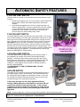
AUTOMATIC SAFETY FEATURES
L120 LOW LIMIT SWITCH
This limit switch is mounted on the exhaust blower housing and has 2 main
functions.
1. Should the fire happen to go out, for any reason, this limit switch will
shut the stove off when the exhaust temperature drops below
120deg F.
2. Upon starting the appliance, the AcuTron control board has a 15
minute “Lighting Mode”, if the stove exhaust does not reach 120deg
F in that 15 minutes the stove will shut off. As soon as the stove
exhaust does reach 120deg F, the limit switch opens and the
AcuTron enters a 5 minute “Safety Delay” mode.
F140 FAN LIMIT SWITCH
Your pellet appliance has a convection fan control limit switch. The room air
fan's (F140) temperature limit snap switch automatically sets the fan on high
when your stove is producing heat faster than the fan is carrying it into the
room. This may occur when the heat control lever is set at [3 or 4] and the
FAN SPEED is set to a very low or off setting. After the fan runs at this
automatic high setting a few minutes, it may cycle back to its lower setting
and may continue to cycle between [HIGH] and your selected setting. The
circulation (room air) fan cycling from high to low is a normal condition as well
as a safety feature of your appliance. To compensate for the fan cycling,
adjust the FAN SPEED to a higher setting.
L250 HIGH LIMIT SWITCH
Your pellet appliance has a high temperature limit switch installed. If
the temperature at the back of the firebox reaches approximately
250deg F., the switch will shut off the electricity going to the Vacuum
Switch and to the Auger Motor. The auger will automatically stop, and
the appliance will shut down when the exhaust temperature cools
(120deg F). If this happens call your dealer or Dansons Customer
Service (1-866-456-9269).
IT IS IMPORTANT TO FIND THE REASON WHY THE UNIT
OVERHEATED.
VACUUM SWITCH
This safety device (mounted on the back panel pillar) detects vacuum in
the exhaust system, firebox, and air intake. If the exhaust blower fails,
the vent pipe becomes plugged, the viewing door is open, or if you are
out of pellets, this switch will sense that there is a lack of vacuum and
will stop the auger from continuing to feed pellets.
If the power does go out, the pellet appliance will stop
running. When the power comes back on, the stove will not
restart if the switch is in the manual mode. If the exhaust
temperature is above 120deg F or the switch is in the manual
position, the stove will start to feed pellets again and may re-
light itself.
NOTE: If power outages are a concern you may wish to purchase a back-up generator system.
For further information contact your local Specialty Retailer, Certified HVAC Service Depot, or Dansons
Group Inc. Customer Service Department at 1-866-456-9269.

Can
adian Comfort Industries V05 8 VULCAN “V” SERIES OWNERS MANUAL
Copyright 2005
www.salesunlimited.com Dansons Group Inc.
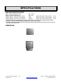
SPECIFICATIONS
HEATING SPECIFICATIONS
Approx. Heating capacity (sq. feet) * 800 – 2,000
Approx. Fuel burn rate per hour ** 1.5 – 5 lbs
Hopper Capacity - Traditional Stove / Insert 40 lbs Approx. Burn time at lowest setting 27 hrs
Hopper Capacity – Bay View Free Standing 60 lbs Approx. Burn time at lowest setting 48 hrs
Hopper Capacity – Bay View Insert / Built-In 40-60 lbs Approx. Burn time at lowest setting 27-48
* Heating capacity will vary depending on floor plan layout of your home, degree of insulation, and the outside
temperature. Fuel size, quality, density and moisture level will also have an effect.
** Pellet size may effect the actual rate of fuel feed and burn times. Fuel feed rates may vary by as much as 20%. Use
PFI listed fuel for best results.
DIMENSIONS

Can
adian Comfort Industries V05 9 VULCAN “V” SERIES OWNERS MANUAL
Copyright 2005
www.salesunlimited.com Dansons Group Inc.
PLANNING & INSTALLATION CHECK LIST
Unless you are knowledgeable and experienced in stove installation, we recommend your VULCAN “V”
SERIES stove receive a Pre-delivery Check and be installed by your local Specialty Retailer or Certified
HVAC Service Depot.
COMPLETE THIS CHECK LIST PRIOR TO INSTALLING YOUR PELLET APPLIANCE:
_____ Carefully read this "Owner's Manual”. SAVE THIS MANUAL.
_____ Have your local Dealer demonstrate all the operational, cleaning and maintenance steps necessary
for your stove.
_____ Select a location. The design of your home and the stove placement will determine its value as a
source of heat. A pellet appliance depends primarily on air circulation to disperse its heat. There are
other practical considerations, which must be considered before a final placement is decided on:
Existing Chimneys, Pellet Fuel Storage, Aesthetic Considerations, Roof Design (rafter
locations & roof pitch), Room Traffic, Clearances to Combustibles, and Existing Wiring.
_____ The installation of this appliance must conform to local codes and applicable state and federal
requirements. Becoming familiar with these requirements before installation is essential.
_____ Sign and keep a copy of the Pre-delivery Check List supplied by your Authorized VULCAN “V”
SERIES Dealer, OR “Dansons Certified Installer”, found inside our appliance or available online.
Register online at www.dansons.com/support
for Extended Warranty.
______ Register your purchase online at www.dansons.com/support.
COMPLETE THIS CHECK LIST WHILE INSTALLING YOUR PELLET APPLIANCE:
_____ Carefully read the ENTIRE installation section first.
_____ Read the Freestanding or Insert or Built-In section (which ever applies)
_____ Determine the location and measurement needed your chosen location.
_____ Be sure to pre-fit all items before you install, fasten or install the stove permanently. Remember
measure twice, cut once.
_____ Ensure ALL joints of “PL” vent and single wall stainless steel liner are tightly connected, sealed
with RTV Silicone, including to the exhaust connector, and is correctly installed. (Follow vent
manufacturer’s instructions.)
COMPLETE THIS CHECK LIST PRIOR TO LIGHTING YOUR FIRST FIRE:
_____ Obtain final inspection and approval by local building officials.
_____ Carefully clean all marks off the brass, nickel or pewter parts before the first fire is lit. Use a soft cloth
and a gentle type cleaner. Caution: Never use an abrasive cleaner on any part of your stove.
_____ Polish the hopper to remove the oil type coating used in manufacturing.
_____ The high temp. stove paint used on your stove may take several hours of burning at a high fuel setting to
fully cure. During this time an odor, which is not harmful, may be evident. The area around the stove
should be well ventilated.
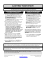
_____ Review and follow the Lighting and Controls Instructions.
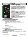
_____ Fill the hopper with quality pellets to prime the unit; Using the CCI “AcuTron”, (figure 5), PUSH the
FEED RATE Touch Pad and this will start the auger and the combustion fan.

Can
adian Comfort Industries V05 10 VULCAN “V” SERIES OWNERS MANUAL
Copyright 2005
www.salesunlimited.com Dansons Group Inc.
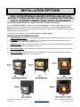
INSTALLATION OPTIONS
READ THIS ENTIRE MANUAL BEFORE YOU INSTALL AND USE YOUR
VULCAN “V” SERIES HEATER. FAILURE TO FOLLOW INSTRUCTIONS MAY
RESULT IN PROPERTY DAMAGE, BODILY INJURY OR EVEN DEATH!
(See specific Installation details for clearances and other installation requirements)
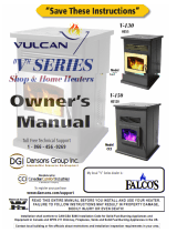
The two VULCAN “V” SERIES models are the: “FPP” Freestanding: a Traditional styled stove mounted on a
pedestal (figure 1) or Leg platform (figure 2), and a Bay View style(figure 3); and the “IPP” Fireplace Insert /
Built-In: a Traditional style (figure 4), and a Bay View style (figure 5). Both models are available in black, pewter or
gold plated doors, legs, and louvers.
All models may be installed to code in both conventional and mobile homes.
INSTALLATION OPTIONS INCLUDE:
1. A FREESTANDING STOVE: Set on a pedestal or legs and placed on a non-combustible floor pad. (figure 1,2 & 3)
2. An ALCOVE: Set on a pedestal and placed on a non-combustible floor pad in compliance with clearance
requirements for an installation in an alcove.
(figure 1, 2 & 3)
3. A HEARTH STOVE: When installed with or without a pedestal on a non-combustible hearth of a masonry or
factory built wood or coal burning fireplace. (figure 1,2 & 3)
4. A FIREPLACE INSERT: When installed, with a shroud, in a masonry or a factory built, wood or coal burning
fireplace. (figure 4 & 5)
5. A BUILT-IN INSERT: When installed on a non-combustible pad, in a wall or custom built mantel and where
adequate airflow around the stove is provided. (figure 4 & 5)

Can
adian Comfort Industries V05 11 VULCAN “V” SERIES OWNERS MANUAL
Copyright 2005
www.salesunlimited.com Dansons Group Inc.
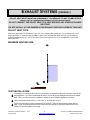
EXHAUST SYSTEMS (GENERAL)
PELLET VENT MUST MAINTAIN A MINIMUM 3” CLEARANCE TO ANY COMBUSTIBLE
(INSTALL VENT AT CLEARANCES SPECIFIED BY THE VENT MANUFACTURER).
DO NOT CONNECT THE PELLET VENT TO A VENT SERVING ANY OTHER APPLIANCE
OR STOVE.
DO NOT INSTALL A FLUE DAMPER IN THE EXHAUST VENTING SYSTEM OF THIS UNIT.
PELLET VENT TYPE:
Must be an approved 3” or 4” Diameter Type ”PL” vent, vented to the outside (fig. 7) or connect the vent to a
factory built type “A” chimney using an adaptor; and/or “All Fuel” Stainless Steel chimney liner for masonry
fireplace installations (fig. 8) . Use 4” dia. vent if vent or liner height is over 15’ or if installation is over 4,000’
above sea level.
MAXIMUM VENTING SIZE:
VENT INSTALLATION:
Termination must exhaust above the air inlet elevation, and parallel or above the exhaust output of the
pellet appliance. It is recommended that at least 3’ of vertical pipe be installed to create some natural
draft. This is to help prevent the possibility of smoke or odor during the appliance shut down.
Horizontal sections must have a ¼” rise every 12” of travel after 3’ long.
Pellet Vent connections must be sealed with HI-Temp RTV Silicone and screwed together with at
least 3 x 3/8” long stainless steel screws. Seal each vent section by injecting a liberal amount of HI-
TEMP RTV silicone sealant into the gap.

Can
adian Comfort Industries V05 12 VULCAN “V” SERIES OWNERS MANUAL
Copyright 2005
www.salesunlimited.com Dansons Group Inc.
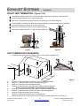
EXHAUST SYSTEMS . . . Continued
PELLET VENT TERMINATION: (Figures 7 & 8)
Termination must be a minimum of 6” above the chimney (B) (note: the chimney must meet local
codes for height above the roof or other obstructions)
Must have an approved cap (to prevent water from entering) or a 45* elbow downturn
If the termination is located on a windy side of house, an approved house shield is recommended to
prevent soot from accumulating on the side of the house.
Must not be located where snow or other materials will plug it.
Must have a “Metal Seal Plate” or “Wall Thimble” at point (A)
Figure 7 Figure 8
VENT TERMINATION CLEARANCES:
• Horizontal terminations must protrude 12” from the wall, vertical terminations 24”
Figure 9
A Minimum 4’ clearance below or beside any door or window which opens.
B Minimum 1’ clearance above any door or window that opens.
C Minimum 3’ clearance from any adjacent building.
D Minimum 7’ clearance above any grade when adjacent to public walkways.
NOTE: Vent may not terminate in covered walkway or breezeway.
E Minimum 2’ clearance above any grass, plants, or other combustible material.
F Minimum 3’ clearance from any forced air intake of any other appliance.
G Minimum 2’ clearance below eves or overhang.
H Minimum 1’ clearance horizontally from combustible wall
.
X Must be a minimum of 36” above the roof and 24” above the highest point of the roof within 10’.
A
B
3’
10’
2’
x
A
A
F
G
4
12”

Can
adian Comfort Industries V05 13 VULCAN “V” SERIES OWNERS MANUAL
Copyright 2005
www.salesunlimited.com Dansons Group Inc.
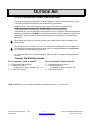
OUTSIDE AIR
Outside air is REQUIRED ON ALL MOBILE HOME INSTALLATIONS.
Outside air is strongly recommended for all other installations. Failure to install intake air may result
in improper combustion as well as the unit smoking during power failures.
Metal pipe, ONLY, either solid or flexible, must be used in all outside air installations.(B)
NOTE: Non-metallic material MUST NOT BE USED for outside air installations.
A wind shield, (C), over the termination of the outside air pipe or a 90 degree elbow or bend directed
away from the prevailing winds MUST be used when an outside air pipe is installed through the side
of a building. Keep the outside air pipe termination at least 1 foot away from the exhaust system
termination.
When outside air is taken from an existing chimney the exhaust system must not terminate in the
same chimney.
The outside air pipe on your stove is 2" OD. The outside air connecting pipe must be at least 2" ID
The outside air connecting pipe must be as short and free of elbows as possible, and must fit over,
(A), not inside, the outside air pipe on your stove.
Air may also be drawn from a vented crawl space under the home. All joints should be sealed and
secured.
Through The Wall Kits Include:
3 FOOT PACKAGE – PART# ACFAKT03 10 FOOT PACKAGE – PART# ACFAKT10
1 – 2” Galvanized Hood c/w screen 1 – 2” Galvanized Hood c/w screen
1 – 2” Aluminum Flex Duct – 1 – 2” Aluminum Flex Duct –
compressed 15” length, extends to 30” – 36” compressed 4’ length, extends to 120”
2 – 2” Worm Gear Clamps 2 – 2” Worm Gear Clamps
NOTE: Available from your local Authorized Dealer or Dansons Group Inc. 1-877-303-3134

Can
adian Comfort Industries V05 14 VULCAN “V” SERIES OWNERS MANUAL
Copyright 2005
www.salesunlimited.com Dansons Group Inc.
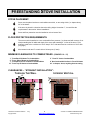
FREESTANDING STOVE INSTALLATION
STOVE PLACEMENT:
Stove must be placed so that no combustibles are within, or can swing within (i.e. drapes doors),
36” of the heater.
If the stove is placed in a location where the ceiling height is less than 7’, it must follow the
requirements in the section “Alcove Installation”.
Stove and floor protection must be installed on a level secure floor
FLOOR PROTECTION REQUIREMENTS:
The stove must be installed on a non-combustible floor protector (i.e. sheet steel with cement, tile or
slate) extending the full width and depth of the stove and extending 6” in front of the stove. Floor
protector needs to be a minimum of 24.5” deep X 30.5” wide and must be a minimum of .018” thick
(26 gauge).
Must extend under and 2” to each side of chimney tee (if used).
MINIMUM CLEARANCES TO COMBUSTIBLES (FIGURES 10 – 15)
1” From Back Of Heater To Combustibles 3” From PL Vent to Combustibles
2” From Side of Heater to Combustibles
1” From Back Corner of Heater to Combustibles 6” Non Combustible Surface In Front Of Heater
16” From Top Of Heater to Combustibles 36” to drapes, doors, anything that can swing
CLEARANCES – “STRAIGHT INSTALLATION”:
Figure 10 Figure 11
6”
1”
10”
6”
1”
2”
12”
HROUGH HE ALL
T T
W
6”
3”
2”
NTERIOR ERTICAL
I V

Can
adian Comfort Industries V05 15 VULCAN “V” SERIES OWNERS MANUAL
Copyright 2005
www.salesunlimited.com Dansons Group Inc.
FREESTANDING INSTALLATION . . . continued
CLEARANCES – “CORNER INSTALLATION”:
Figure 12 Figure 13
Note: If interior vertical vent is used, the clearance to the back wall is determined by the upward-turned
elbow or “Tee”. It will vary in depth depending on the brand of PL vent used.
Before placing the stove, connect the elbow or “Tee” and measure off the 3” clearance.
ALCOVE INSTALLATION:
Minimum clearances to combustibles for a stove. (Figures 14 and 15)
1 inch from the back
16 inches from the top
6 inches from the sides
30 inches deep
Figure 14 Figure 15
1”
2
”
12”
6
”
HROUGH HE ALL
T T W
ORNER
45 C
3
”
6”
2”
NTERIOR
ERTICAL
I
V
ORNER
45 C
1”

Can
adian Comfort Industries V05 16 VULCAN “V” SERIES OWNERS MANUAL
Copyright 2005
www.salesunlimited.com Dansons Group Inc.
FREESTANDING INSTALLATION . . . continued
Figure 16
NOTE: Some horizontal, through the wall installations may require a Clean-Out Tee and a minimum 3’ vertical rise
of pipe inside or outside the building to help draft the stove. This is required if a proper burn cannot be maintained,
after the stove has been tested and the airflow set. This is due to backpressure in the exhaust, caused by the
airflow around the house.
THROUGH THE WALL, DIRECT VENT INSTALLATION. (Figure 18)
1. Select the location for your stove, design the exhaust system and determine the brand and size of "PL" vent to
be used.
2. Position the floor pad.
3. Following the "PL" vent manufacturer's specifications, mark and cut a hole through the wall to accommodate
the wall thimble, (F), and the outside air pipe, (I), if outside air is to be used. Remember that the outside air
intake must be located no closer than 12” from the vent exhaust. Try to avoid cutting wall studs, and use
extreme caution to avoid cutting into power or water lines within the wall of your home.
4. Install the wall thimble, (F). Be sure to run a bead of silicone around the outside edges of the wall thimble to
reduce drafts, both inside and outside. Insert the proper size of "PL" vent, (E), through the wall thimble, (F).
5. Place your stove on the floor pad, close to its final position. Leave room to connect the "PL" vent to “Quick
Connect” end collar. If not already factory installed, Install the gasket (B) and “Quick Connect” exhaust end (C)
to your stove to the “Quick Connect” mounting plate. Use the 4 x 7/16” nuts, supplied and secure tightly.
6. Place a bead of RTV silicone around the end collar of the “Quick Connect” of your stove's exhaust, (C). Firmly
push the “PL” vent pipe adaptor (J) into the bead of RTV silicone.
Note: If 4" PL vent is required, use an 3” to 4” Pipe Adaptor Increaser, (J), on the stove exhaust pipe.
7. Connect the length of "PL" vent, (E), that is in the thimble, (F), onto the pipe adaptor (D). Fasten together with
at least three sheet metal screws (approx. 3/8” in length). Place a bead of RTV silicone around the connection.
8. Place your stove in its final position on the pad. Place another bead of
RTV silicone around the “PL” vent (E) and the inside of the wall thimble,
to stop cold air drafts.
9. On the outside of the building, place an exhaust cap (G) or a 45 degree "PL"
type elbow, (G), onto the end of the horizontal "PL" vent, (E).
Optionally, place a rodent screen cap, (G), (may be required in some locals),
on the end of the elbow, (G). Secure all connections using 3 sheet metal
screws and run a bead of RTV silicone around all connections and around
the “PL” vent pipe and the outside of the wall thimble.
Note: The end of the exhaust pipe must extend a minimum of 12” from the
6”
1”
10”
6”
1”
2”
12”

Can
adian Comfort Industries V05 17 VULCAN “V” SERIES OWNERS MANUAL
Copyright 2005
www.salesunlimited.com Dansons Group Inc.

Can
adian Comfort Industries V05 18 VULCAN “V” SERIES OWNERS MANUAL
Copyright 2005
www.salesunlimited.com Dansons Group Inc.
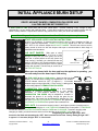
MOBILE HOME INSTALLATION
CAUTION: DO NOT INSTALL STOVE IN SLEEPING ROOM
THE STRUCTURAL INTEGRITY OF THE MANUFACTURED HOME FLOOR,
CEILING/ROOF MUST BE MAINTAINED!
Your VULCAN “V” SERIES stove has been tested and listed for mobile home installation. It may be installed
in a mobile home as a "Free Standing Stove", a "Hearth Stove", as an "Insert" installed in an existing wood or
coal-burning fireplace or as an "Built –In Insert" installed with a mantel.
In addition to all previously detailed installation requirements, mobile home installations
must meet the following requirements:
Permanently bolt your stove to the floor, (A). Figure 23, 24
Electrically ground your stove or the pedestal to the steel frame of the home. Use a number 8 gauge copper
wire, (B) figure 24, or equivalent.
The stove must have a permanent outside air source with a ¼ inch screen over the inlet.
Figure 23, (B,C, D)
For transportation all chimney / vent above the mobile home must be removed.
“PL” or ”L” Vent must be 3” or 4” and must extend a minimum or 36” above the roofline of the mobile
home and must be installed using a UL/ULC listed ceiling fire stop (J), figure 23, and
rain cap (L), figure 23.
INSTALL VENT AT CLEARANCES SPECIFIED BY THE VENT MANUFACTURER.
A
Floor Pad
B
Combustion Air Intake
C
Fresh Air Duct
D
Fresh Air Hood
E
Stove Exhaust
F
Pipe Adapter
G
Clean Out Tee
H
Tee Support Bracket
I
Pipe
J
Firestop Spacer / Ceiling Support
K
Roof Flashing / Storm Collar
L
Rain Cap
Figure 23 Figure 24
Note: When moving your Mobile Home, all exterior venting must be removed while Mobile Home is
being relocated. Upon completion of relocation all venting must be reinstalled and securely fastened.
B
A
C
D
G
H
I
J
K
L
FRAME
HEARTH PAD
FLOOR
B
GROUND
WIRE
A
BOLT(S)

Can
adian Comfort Industries V05 19 VULCAN “V” SERIES OWNERS MANUAL
Copyright 2005
www.salesunlimited.com Dansons Group Inc.
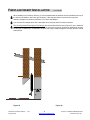
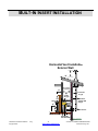
FIREPLACE INSERT INSTALLATION
VENTING INTO AN EXISTING CHIMNEY:
CAUTION:
MAKE SURE THE CHIMNEY AND FIREBOX ARE CLEAN AND FREE OF SOOT AND ASHES BEFORE
INSTALLATION BEGINS. FAILURE TO DO SO MAY RESULT IN THE TRANSFER OF SOOT INTO THE ROOM
BY WAY OF THE CONVECTION FAN.
The VULCAN “V” SERIES Insert may be installed in a masonry or factory built fireplace as shown in Figure 25 & 26
INSTALLING SOLID-FUEL INSERTS INTO FACTORY BUILT FIREPLACES:
The insert must be tested and meet the requirements of UL 1482 (U.S.) and or ULC 8628 (Canada) when
tested in a masonry fireplace built per ULC S628.
The factory-built fireplace must be listed per UL 127 or ULC 8610.
Clearances obtained from the masonry fireplace tests are also relevant for installation in factory-built
fireplaces.
Installation must include a full height listed chimney liner meeting type HT requirements (2100 degree F.)
per UL 1777 (U.S.) or ULC 8635 (Canada). The stainless steel liner must be securely attached to the
insert flue collar and the chimney top.
Means must be provided to prevent room air passage to the chimney cavity of the fireplace. This may be
accomplished by sealing the damper area around the chimney liner, or sealing the fireplace front.
The airflow within and around the fireplace shall not be altered by the installation of the insert (i.e. no
louvers or outlet ports are blocked), unless specifically tested as such for each factory-built fireplace
manufacturer and model line. (Note - using a louvered faceplate (surround) complies with this
requirement).
Alteration of the fireplace in any manner is not permitted with the following exceptions;
1. External trim pieces which do not affect the operation of the fireplace may be removed providing
they can be stored on or within the fireplace for re-assembly if the insert is removed.
2. The chimney damper may be removed to install the chimney liner.
Circulating air chambers (i.e. in a steel fireplace liner or metal heat circulator) shall not be blocked.
Means must be provided for removal of the insert to clean the chimney flue.
Inserts that project in front of the fireplace must be supplied with appropriate supporting means.
A permanent metal warning label must be attached to the back of the fireplace stating
that the fireplace must be restored to its original condition for safe use with out the insert. This sticker is
supplied in the packaging for the insert shroud.
(See Following statement)
THIS FIREPLACE HAS BEEN ALTERED TO ACCOMMODATE
A FIREPLACE INSERT AND SHOULD BE INSPECTED BY A
QUALIFIED PERSON PRIOR TO RE-USE AS A CONVENTIONAL FIREPLACE!

Can
adian Comfort Industries V05 20 VULCAN “V” SERIES OWNERS MANUAL
Copyright 2005
www.salesunlimited.com Dansons Group Inc.
FIREPLACE INSERT INSTALLATION … CONTINUED
When installing into a masonry chimney, it is recommended that the exhaust vent be extended to the top of
the chimney as shown to the lower right. However, if the vent pipe does not extend to the top of the
chimney, the pipe must extend a minimum of 18” above the damper.
You must seal the damper area with a steel plate when using the direct connection method.
The Vent Pipe Must Extend Above The Damper into the first tile of the flue liner (Figure 25) in the USA and
to the top of the chimney CANADA (Figure 26). The chimney must not be corroded or damaged in any way
for this type of installation to be permitted. A direct vent may be made through the chimney structure if local
codes permit.
Figure 25 Figure 26
Page is loading ...
Page is loading ...
Page is loading ...
Page is loading ...
Page is loading ...
Page is loading ...
Page is loading ...
Page is loading ...
Page is loading ...
Page is loading ...
Page is loading ...
Page is loading ...
Page is loading ...
Page is loading ...
Page is loading ...
Page is loading ...
Page is loading ...
Page is loading ...
Page is loading ...
Page is loading ...
-
 1
1
-
 2
2
-
 3
3
-
 4
4
-
 5
5
-
 6
6
-
 7
7
-
 8
8
-
 9
9
-
 10
10
-
 11
11
-
 12
12
-
 13
13
-
 14
14
-
 15
15
-
 16
16
-
 17
17
-
 18
18
-
 19
19
-
 20
20
-
 21
21
-
 22
22
-
 23
23
-
 24
24
-
 25
25
-
 26
26
-
 27
27
-
 28
28
-
 29
29
-
 30
30
-
 31
31
-
 32
32
-
 33
33
-
 34
34
-
 35
35
-
 36
36
-
 37
37
-
 38
38
-
 39
39
-
 40
40


Dansons Group Indoor Fireplace V-200FPP User manual
- Category
- Stoves
- Type
- User manual
Ask a question and I''ll find the answer in the document
Finding information in a document is now easier with AI
Related papers
-
 Dansons Group Stove V-50 User manual
-
 Dansons Group CC1 User manual
-
 Dansons Group HSPP2 Owner's manual
-
 Dansons Group CC1 User manual
-
 Dansons Group CC1 User manual
-
 Dansons Group Wire User manual
-
 Dansons Group CCGB 1 User manual
-
 Dansons Group IGB User manual
-
 Dansons Group CAN/CSA B365 User manual
-
 Dansons Group 680 User manual


Other documents
-
 Wood Heating Solutions NC-30 Operating instructions
-
US Stove Company 5660E Owner's manual
-
United States Stove Ashley AP5660 Owner's manual
-
-
USSC 5660 User guide
-
Ashley AP5660L Installation guide
-
-
Vulcan-Hart Home Heaters User manual
-
Kozyheat Olivia Owner's manual
-
