Watts Isomix-HC User manual

Type
User manual

Watts Isomix-HC: Control the flow temperature in surface heating/cooling systems with precision. Easily maintain a comfortable indoor climate by constantly monitoring and adjusting the water temperature, ensuring optimal energy efficiency and comfort.

Watts Isomix-HC: Control the flow temperature in surface heating/cooling systems with precision. Easily maintain a comfortable indoor climate by constantly monitoring and adjusting the water temperature, ensuring optimal energy efficiency and comfort.

Isomix-HC
Control station for load-based control of the flow
temperature in surface heating/cooling systems
Installation and Operating Manual
(translated from the original operating manual)
WattsWater.eu
2ISOMIX-HC-IM-DE-W-UK-03-2022-Rev.5 | Part no. 10070436
EN ENGLISH
Contents
1 General information ............................... 2
1.1 Important information about this manual ................... 2
1.2 Product conformity .................................................... 2
1.3 Product features ........................................................ 2
2 Safety ........................................................3
2.1 Presentation of safety information .............................. 3
2.2 Important safety information ...................................... 3
2.3 Intended use .............................................................. 3
2.4 Foreseeable misuse ................................................... 3
2.5 Responsibilities of the plant operator ......................... 3
2.6 Personnel groups ...................................................... 3
2.7 Information on the operating environment ................. 3
3 Structure .................................................. 4
4 Function ................................................... 4
5 Technical Data ........................................ 4
6 Overall dimensions ................................. 5
7 Pressure loss diagram ........................... 5
8 Installation and commissioning ............. 6
8.1 Examples of applications ........................................... 6
8.2 Installation .................................................................. 7
8.3 Temperature limiter .................................................... 7
8.4 Mounting in combination with Heat Interface Unit HIU 2 ......... 7
8.5 Inbetriebnahme .......................................................... 8
9 Wartung ................................................... 8
9.1 Annual maintenance .................................................. 8
9.2 Replacement of wear parts ....................................... 8
10 Troubleshooting .......................................9
11 Disposal ................................................. 10
11.1 Return to the manufacturer .......................................10
11.2 Notification of administrative bodies and the manu-
facturer ....................................................................10
12 Warranty ................................................ 10
1 General information
1.1 Important information about this manual
NOTICE The plant operator is responsible for
ensuring compliance with the local laws and regulati-
ons (e.g. accident prevention regulations, etc.).
Incorrect operation or operating the Isomix-HC outside
the specifications invalidates all warranty claims.
This installation and operating manual
is an integral part of the Isomix-HC
contains instructions and information about safe and cor-
rect installation and commissioning of the Isomix
must be available to all users throughout the entire service
life of the Isomix
is intended for trained personnel who are familiar with the
applicable standards and regulations and, in particular,
with the relevant safety concepts, operation and mainte-
nance of the Isomix-HC
is protected by copyright and may not be altered without
the manufacturer’s permission
1.2 Product conformity
A Declaration of Conformity according to Machinery Directive
2006/42/EC has been issued for the Isomix-HC product.
1.3 Product features
All connections to the system have 1" male thread and flat
sealing
Very convenient controls, compact, space-saving design.
ISOMIX-HC-IM-DE-W-UK-03-2022-Rev.5 | Part no. 10070436 3
EN
ENGLISH
2 Safety
2.1 Presentation of safety information
!
DANGER DANGER indicates an imminent danger
that may cause serious physical injury or death if the
appropriate safety precautions are not in place.
!!
WARNING WARNING indicates a danger arising
through incorrect behavior (e.g. misuse, disregarding
notices, etc.) that may cause serious physical injury or
death.
!!
CAUTION CAUTION indicates a potentially
dangerous situation that may cause minor or slight
injuries if the appropriate safety precautions are not in
place.
NOTICE NOTE indicates a situation that may
cause material damage if the corresponding precauti-
ons are not taken.
2.2 Important safety information
Before using the Isomix-HC, read this operating manual
through carefully.
Connect the Isomix-HC only to a power source that corre-
sponds to the mains voltage specified on the rating plate of
the Isomix-HC.
The power supply to the Isomix-HC must be disconnected
prior to maintenance, cleaning and repair work.
Maintenance, cleaning and repair work may be carried out
by trained specialist personnel only.
The Isomix-HC must not be used if it is damaged or is no
longer operating correctly. In this case, contact your spe-
cialist dealer immediately.
Observe the maintenance instructions and intervals.
Protect the Isomix-HC from the weather.
Never use the Isomix-HC outdoors.
The unit may be used only in accordance with its intend-
ed use.
2.3 Intended use
The control station Isomix-HC is used for constant mainte-
nance of the flow temperature in surface heating systems.
The control station is intended for use in dry rooms in resi-
dential or commercial areas. It is usually installed in the heat-
ing room or in a distribution cabinet.
The Isomix-HC is not intended to be operated by people
(including children) with limited physical, sensory or mental
capacities, or by people with insufficient experience or previ-
ous knowledge.
2.4 Foreseeable misuse
The following is considered to be foreseeable misuse:
Operating the Isomix-HC beyond its specifications.
Improper use of the Isomix-HC.
Modifications to the Isomix-HC that have not been agreed
with the manufacturer.
Use of replacement or wear parts that have not been
approved by the manufacturer.
Operating the Isomix-HC outdoors.
2.5 Responsibilities of the plant operator
The plant operator must ensure that:
the Isomix-HC is used only for its intended purpose
the Isomix-HC is installed, operated and maintained
according to the specifications of the installation and oper-
ating manual
the Isomix-HC is operated only in accordance with local
regulations and occupational health and safety regulations
all precautionary measures have been taken to avoid dan-
gers originating from the Isomix-HC
all precautions for first aid and firefighting have been taken
only authorized and trained users have access to the
Isomix-HC and operate it
users have access to this installation and operating manual
at all times
2.6 Personnel groups
Only qualified persons may install and operate the Isomix-HC
and carry out maintenance work.
Operators
Operators are deemed to be qualified if they have read these
operating instructions and understood the potential hazards
associated with improper behavior.
Fitters/commissioning engineers
Fitters/commissioning engineers are in a position to carry out
work on the Isomix-HC, taking into consideration the appli-
cable standards, provisions, regulations and laws and their
technical training and technical knowledge, and can detect
and prevent potential hazards.
2.7 Information on the operating environment
Corrosion and chemical and physical reactions can damage
the control station.
The system planner is responsible for evaluating these
parameters and developing remedies.
4ISOMIX-HC-IM-DE-W-UK-03-2022-Rev.5 | Part no. 10070436
EN ENGLISH
3 Structure
B
D
C
A
1
3
5
8
9
10
11
4
6
2
7
Fig. 3-1 Structure
1Circulation pump
23-point actuator
33-way mixer valve
4Connection for flow sensor 11 1)
5Eccentric screw connection with Thermometer
6Insert check valve
7Return temperature sensor connection 1/8" (option)
8Temperature limiter (optional)
9Climatic controller CC-HC
10 External temperature sensor
11 Flow temperature sensor 1/8"
APrimary supply (1" male thread)
BPrimary return (1" male thread)
CSurface heating/cooling supply (1" union nut)
DSurface heating/cooling return (1" union nut)
1) Flow temperature sensor is factory-connected to Isomix-HC
4 Function
The set value for the flow temperature, determined by the cli-
matic controller CC-HC (9) using the current external tem-
perature and the heating curve, is monitored continuously by
the flow sensor (11). If there are temperature fluctuations, the
controller causes the 3-point actuator (2) to open or close the
3-way mixer (3), or to maintain the valve position when the set
value is reached.
The hot water fed in from the primary circuit (A) via the 3-way
mixer (3) is mixed directly with the water from the underfloor
heating return (D). The mixed medium is distributed by the
pump (1) to the heating circuit manifold and from there to the
connected heating circuits.
The underfloor heating flow temperature can be seen on the
climatic controller (9).
There is a non-return valve (6) between the primary feed and
the return connection on the mixer valve, which prevents a
short-circuit in the primary circuit.
5 Technical Data
Hydraulic performance data
Max. operating pressure 10 bar
Max. ambient temperature
40 °C
Max. operating temperature 80 °C
Setting range of supply
temperature 20 - 70 °C
Kvs value 3,2 m³/h
Heating demand
14 kW at ∆T=10K
Differential pressure
max. 500 mbar
Media Water/water-glycol mixture as
per VDI 2035/ÖNORM (Austrian
standard) 5195
Electrical connection
Operating voltage
230 V
Frequency
50 Hz
Connections to pipe network
Primary (heat generator)
1" male thread, flat sealing
Secondary (heat distribution) 1" fl. (union nut), flat sealing
Toques of the fitting
¾"
35 Nm
1" 55 Nm
Materials
Fittings Brass CW617 N, nickel plated
Seals and O-rings AFM34/2 and EPDM
Plastics
Impact resistant and tempera-
ture resistant
Circulation pump, climatic controller, actuator and temperature
limiter
Technical data can be found in the enclosed technical
documentation.
ISOMIX-HC-IM-DE-W-UK-03-2022-Rev.5 | Part no. 10070436 5
EN
ENGLISH
6 Overall dimensions
G1" G1"
1"Fl. 1"Fl.
82 22,5
65,5
25
ca. 212
210
ca. 109
ca. 98
Fig. 6-1 Overall dimensions
7 Pressure loss diagram
1
10
100
1.000
100 1.000 10.000
Fig. 7-1 Pressure loss diagram
Flow rate [l/h]
Pressure loss [mbar]
6ISOMIX-HC-IM-DE-W-UK-03-2022-Rev.5 | Part no. 10070436
EN ENGLISH
8 Installation and commissioning
!
DANGER Electrical energy!
Risk of death from electric shock.
Work on parts carrying live voltage must be carried out
by qualified electricians only.
Disconnect the power supply of the system and secure it
to prevent it from being switched on again before carrying
out any installation, maintenance, cleaning or repair work.
NOTICE The installation and commissioning of
the Isomix-HC must be carried out only by trained per-
sonnel who have been authorized by the manufacturer.
!!
CAUTION When repairing the unit or replacing
parts, be sure to observe the specified installa-
tion positions and flow directions of the parts being
replaced!
!!
CAUTION Material damage!
Pressure shocks may occur if the stop valve is opened
or closed quickly.
Always open and close the stop valves slowly and in a
controlled way.
8.1 Examples of applications
M
>T°C
M
>T°C
M
>T°C
M
>T°C
ISOMIX-HC ISOMIX-HC
10
1
7
8
92 3
18
17
16
15
4
5
6
13
7
516
6
19
17
4
15
23
1
8
9
System diagram of radiant panel heating / cooling
Reversable heat pump
System diagram of radiator and radiant panel heating Heat
generator. Separated ascending pipes.
System diagram of radiator and radiant panel heating/ cooling
Separated boiler and chiller. Separated ascending pipes.
ISOMIX-HC
10
15
5
6
16
20
2
3
4
1
8
9
11
A
A
A
13
14 14
14 14
CC
B
B
B
12 12
DD
7
ISOMIX-HC
15
6
4
1
13
9
8
2
3
5
7
17
18
16
10 20 11
14
14
C
D
13
14
14
AA
BB
C
D
A B
System diagram of radiant panel heating / cooling
Separated boiler and chiller.
1Circulation pump for panel
heating / cooling
23 - position actuator
3Mixing valve
4Check valve
5Climatic controller CC-HC
6Outdoor temperature sensor
7Supply temperature sensor
8Temperature limiter
9Return temperature sensor (option)
10 Heat generator
11 Primary circulation pump
12 Heating element / radiator
13 Heating manifold (e.g. HKV2013AF)
14 Fill and drain cocks
15 Shut-off valves (recommendable)
16 Room thermostat or optional
Radio-Hygrostat
17 Chiller
18 Zone valve
19 Reversible heat pump (heating and
cooling)
20 Hydraulic separator
APrimary supply
BPrimary return
CPanel heating / cooling supply
DPanel heating / cooling return
ISOMIX-HC-IM-DE-W-UK-03-2022-Rev.5 | Part no. 10070436 7
EN
ENGLISH
8.2 Installation
All screw fittings must be checked and tightened if
necessary prior to installation and commissioning!
For the torques of the fitting see „5 Technical Data“ on
page 4.
!!
WARNING Hot water!
Risk of severe scalding.
Do not reach into the hot water when emptying the
Isomix-HC. Ensure that the Isomix-HC has cooled
down before carrying out maintenance, cleaning and
repair work.
During installation it must be ensured that:
the cables from the pump and temperature limiter
are not damaged or kinked
the sensor capillary tube is not damaged or kinked
The cables must not be under tension.
1. Fit the control station to the manifold with the 1" nuts and
associated seals.
The control station can be fitted on the right or left of
the manifold by turning the eccentric screw fitting (5,
Fig. 8-1), also upside down.
2. Fit the temperature limiter to the supply collector pipe on
the manifold. Set the temperature on the (optional) tem-
perature limiter to approx. 55 °C.
3. Connect the control station to the power supply.
Further information about electrical connection of the
control station can be found in the separate documen-
tation for the assemblies.
4. Set the temperature on the (optional) temperature limiter
to approx. 55 °C.
8.3 Temperature limiter
In the event of a fault, the temperature limiter switch-
es off the circulation pump and so avoids overheating
of the surface heating system.
The temperature limiter must be fitted to the supply of the
heating circuit manifold.
Set the temperature on the (optional) temperature limiter to
approx. 55 °C.
8.4 Mounting in combination with Heat
Interface Unit HIU 2
For use in combination with the Watts HIU 2 Heat Interface
Unit, the Isomix-HC must be converted (overhead) and the
eccentric rotated.
1. Release nut (A, Fig. 8-1)
2. Rotate eccentric (5, Fig. 8-2)
3. Position the temperature limiter (8, Fig. 8-2)
A
5
Fig. 8-1
8
5
Fig. 8-2
NOTICE To ensure that the pump runs only when
heat is required, the manufacturer recommends con-
necting the pump to a pump relay (e.g. the pump logic
of an electrical control distributor that also controls
the actuators). Alternatively, the pump can be operat-
ed with a timer switch.
8ISOMIX-HC-IM-DE-W-UK-03-2022-Rev.5 | Part no. 10070436
EN ENGLISH
8.5 Inbetriebnahme
1. Connect the control station to the pipe network.
2. Shut off the ball valves (15).
3. Switch off the pump and close all of the heating circuits
on the distributor.
It is sufficient to close the valves in the return of the
heating circuit manifold with the protection caps.
4. Fill the manifold and control station with hot water (in
accordance with VDI 2035):
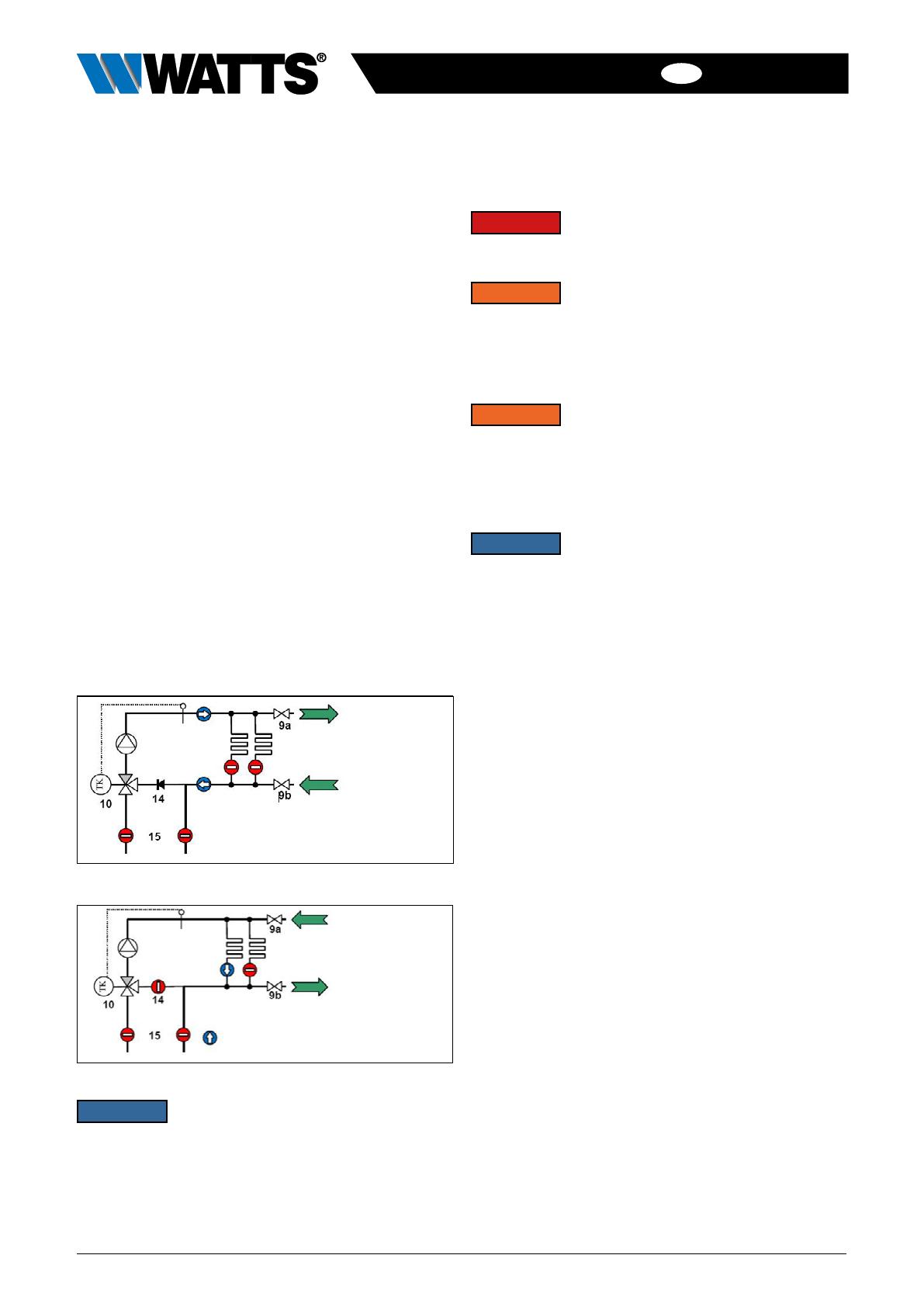
5. connect the filling hose to the fill and drain valve on the
return (9b, Fig. 8-3) and the draining hose to the fill and
drain valve on the supply (9a, Fig. 8-3).
Heating circuits are closed.
6. Open both fill and drain valves and fill the manifold and
control station until water comes out of the fill and drain
valve on the supply. Close both fill and drain valves.
7. To fill and flush the heating circuits, connect the filling
hose to the supply fill and drain valve (9a, Fig. 8-4) and
the emptying hose to the return fill and drain valve (9, Fig.
8-4).
8. Open the heating circuit to be flushed.
9. Open fill and drain valve and flush out the heating circuit
in the direction of flow until the air and any contamination
has been removed from the circuit completely.
The non-return valve (14) in the mixer bypass prevents
any short circuit when flushing.
10. Repeat the process for all the heating circuits.
Fig. 8-3
Fig. 8-4
NOTICE Flushing is permitted only in the direction
of flow of the heating circuits, i.e. the water must enter
through the flow manifold and come out of the return!
The drain must always be open, as otherwise the high
water pressure could damage the heating system.
The instructions on flushing in the operating manual
for the heating circuit manifold must also be observed.
9 Wartung
!
DANGER Electrical energy!
Perform maintenance work on the Isomix-HC only
when the power supply has been disconnected.
!!
WARNING Hot water!
Risk of severe scalding.
Do not reach into the hot water when emptying the
Isomix-HC. Ensure that the Isomix-HC has cooled
down before carrying out maintenance, cleaning and
repair work.
!!
WARNING Hot surfaces!
Risk of serious burns.
Do not touch the pipes or components during opera-
tion. Ensure that the Isomix-HC has cooled down befo-
re carrying out maintenance, cleaning and repair work.
Wear heat-resistant safety gloves if it is necessary to
carry out work on hot components.
NOTICE Maintenance of the Isomix-HC must be
carried out only by trained personnel who have been
authorized by the manufacturer.
9.1 Annual maintenance
1. General visual inspection
Check the control station for leaks and retighten sealing
connections or replace seals, as required.
2. Functional check
Check that settings and operating and performance
parameters are set correctly.
Check flow noise during operation.
Ask users if there are any noticeable problems.
3. Action to be taken following maintenance work
Check that all screw fittings that were unscrewed have
been retightened and retighten if necessary.
Remove all tools, materials and other equipment used from
the working area.
Restore the power supply.
Slowly pressurize the Isomix-HC and vent it.
Readjust the system settings if required.
9.2 Replacement of wear parts
Please note that the Isomix-HC contains parts that, for tech-
nical reasons, are subject to wear depending on the intensity
of use, even if the specified care and maintenance has been
provided.
This applies especially to mechanical parts and parts that
come into contact with water and steam, such as seals,
valves, etc.
By their nature, defects caused by wear do not constitute a
fault and are therefore not covered by the warranty or any
guarantee. Nevertheless, these defects and malfunctions
must be remedied by trained specialist personnel only.
Contact your specialist dealer for this.
ISOMIX-HC-IM-DE-W-UK-03-2022-Rev.5 | Part no. 10070436 9
EN
ENGLISH
10 Troubleshooting
Fault
Possible cause Remedy
1Underfloor heating circuits do not heat up; pump not running
1.1 Temperature limiter (TL) is switching the control station
pump off.
Reason: TL setting is too low.
Set TL to approx. 10 K higher than the underfloor heating
flow temperature.
Note the maximum permitted temperature for the under-
floor heating!
The switching difference of the TL is approx. 5 K.
The control station is ready to operate more quickly if
the TL is removed briefly to cool down to its switching
temperature.
1.2 TL is switching the control station pump off.
Reason: The pump remains switched on despite closed
underfloor heating circuits. The water inside the control sta-
tion is being heated by waste heat from the pump. The TL
switches the pump off when the maximum temperature is
reached!
Remove TL from the control station and fit to supply heating
circuit manifold.
Use electrical control distributor with pump logic (relay). The
pump logic ensures that the pump runs only if at least one
underfloor heating circuit is open.
1.3 The pump is connected to a room thermostat or electrical
control distributor.
If all actuators are closed, the pump switches off. During a
lengthy shutdown, the underfloor heating flow cools down.
The controller therefore causes the 3-way mixer valve to
open. Hot water is injected from the primary heating circuit.
As a result, the control station heats up. When the maxi-
mum temperature of the TL is reached, the contact opens.
The pump does not switch on again.
Remove TL from the control station and fit to supply heating
circuit manifold.
See 1.1
2Underfloor heating flow temperature cannot be set to the required value or the feed temperature fluctuates
significantly
2.1 Supply and return on the control station have been mixed
up Check that all connections on the control station are cor-
rect (see Section "Structure" on page 5)
2.2 The head / pumping level of the pump is set too low Change the pump setting (see separate pump instruction
manual).
2.3 The differential pressure of the primary pump is too high
(>500mbar) Change the pump setting (see separate pump instruction
manual) or fit differential pressure controller.
2.4 The heating load is too high for the control station, i.e. heat
consumption exceeds the nominal output of the control sta-
tion. This condition can come about temporarily, for exam-
ple, when heating up a "cold" floor.
Establish maximum heat requirement and compare with
nominal output. The heating circuits may have to be shared
with a second control station with a corresponding heating
circuit distributor.
If this is caused by heating up the underfloor heating for the
first time, it may start working normally after the heating up
phase (2 – 3 days). This is particularly likely in the case of
operation at the upper nominal output limit.
ISOMIX-HC-IM-DE-W-UK-03-2022-Rev.5 | Part no. 10070436
Watts Industries Deutschland GmbH
Godramsteiner Hauptstr. 167 • 76829 Landau • Deutschland
Tel. +49 6341 9656 0 • Fax +49 6341 9656 560
WIDE@wattswater.com • www.wattswater.eu
The descriptions and photographs contained in this product specication sheet are supplied by way of information only and are not binding.
Watts Industries reserves the right to carry out any technical and design improvements to its products without prior notice. Warranty: All sales and contracts for sale are expressly
conditioned on the buyer’s assent to Watts terms and conditions found on its website at www.wattswater.de/agb. Watts hereby objects to any term, different from or additional to Watts
terms, contained in any buyer communication in any form, unless agreed to in a writing signed by an ofcer of Watts.
© 2022 Watts
11 Disposal
!!
WARNING Potential for contamination of the
environment and groundwater from improper disposal!
The legal regulations and guidelines in the country of
operation must be observed when disposing of com-
ponents and operating materials.
1. Ensure that all assemblies and components are
de-energized.
2. Disassemble the Isomix-HC properly or commission a
specialist company to do so.
3. Sort the assemblies and component parts into recyclable
materials, hazardous substances and operating materials.
4. Dispose of the assemblies and components in accord-
ance with local laws and regulations or take them to be
recycled.
11.1 Return to the manufacturer
Get in contact with the manufacturer if you would like to
return the Isomix-HC or parts of it.
11.2 Notication of administrative bodies and
the manufacturer
Inform the manufacturer of decommissioning and disposal of
the Isomix-HC for statistical purposes.
12 Warranty
WATTS products are tested extensively. WATTS there-
fore guarantees only to replace or repair components of the
products supplied free of charge – at the sole discretion of
WATTS – if, in the opinion of WATTS, they exhibit verifia-
ble manufacturing faults. Warranty claims due to defects or
defects of title may be asserted within one (1) year of deliv-
ery/transfer of risk. Excluded from the warranty is damage
attributable to normal product use or friction and to dam-
age resulting from modifications or unauthorized repairs to
the products, for which WATTS rejects all claims for com-
pensation (direct or indirect). (For more detailed information,
please refer to our website.) In all cases, supply is subject to
the General Terms and Conditions, which can be found on
www.wattswater.eu/gtc/.
  • Page 1 1
  • Page 2 2
  • Page 3 3
  • Page 4 4
  • Page 5 5
  • Page 6 6
  • Page 7 7
  • Page 8 8
  • Page 9 9
  • Page 10 10

Watts Isomix-HC User manual

Type
User manual

Watts Isomix-HC: Control the flow temperature in surface heating/cooling systems with precision. Easily maintain a comfortable indoor climate by constantly monitoring and adjusting the water temperature, ensuring optimal energy efficiency and comfort.

Ask a question and I''ll find the answer in the document

Finding information in a document is now easier with AI