Keller HPX User manual
- Category
- Measuring, testing & control
- Type
- User manual
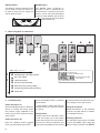
Keller HPX is a high-pressure calibrator that enables pressure generation up to 700 bar relative. It allows accurate measurement and documentation of the characteristic of a connected test object. The measured pressure progression can be displayed, evaluated, and saved with a computer monitoring program (CCS30).
Keller HPX is a high-pressure calibrator that enables pressure generation up to 700 bar relative. It allows accurate measurement and documentation of the characteristic of a connected test object. The measured pressure progression can be displayed, evaluated, and saved with a computer monitoring program (CCS30).


-
 1
1
-
 2
2
-
 3
3
-
 4
4
-
 5
5
-
 6
6
-
 7
7
-
 8
8
-
 9
9
-
 10
10
-
 11
11


Keller HPX User manual
- Category
- Measuring, testing & control
- Type
- User manual
Keller HPX is a high-pressure calibrator that enables pressure generation up to 700 bar relative. It allows accurate measurement and documentation of the characteristic of a connected test object. The measured pressure progression can be displayed, evaluated, and saved with a computer monitoring program (CCS30).
Ask a question and I''ll find the answer in the document
Finding information in a document is now easier with AI
in other languages
- Deutsch: Keller HPX Benutzerhandbuch
Related papers
Other documents
-
Teledyne API T703 User manual
-
-
-
-
-
 Teledyne 703E User manual
-
 Teledyne T700U User manual
-
Fluke 718 Tryckkalibrator User manual
-
 Teledyne VCR T703U User manual
-


