Airmar DST800 Owner's manual

Type
Owner's manual

Airmar DST800 is a multisensor device that combines depth, speed, and temperature readings into one compact and versatile package. Its robust design and ease of installation make it a popular choice for boaters of all levels. With its retractable thru-hull design, the DST800 can be easily installed in a variety of hull types, including fiberglass, metal, and wood.

Airmar DST800 is a multisensor device that combines depth, speed, and temperature readings into one compact and versatile package. Its robust design and ease of installation make it a popular choice for boaters of all levels. With its retractable thru-hull design, the DST800 can be easily installed in a variety of hull types, including fiberglass, metal, and wood.

D-17-435-01 rev. 14 17-435-01-rev. 14 04/01/20
Thru-Hull: Retractable with Valve
TRIDUCER® Multisensor
Models: DST800, DST810
Patent http://www.airmar.com/patent.html
Record the information found on the cable tag for future reference.
Part No._________________Date___________Frequency________kHz
CAST App for DST810
Download the CAST App by Airmar to view,
analyze, and share DST810 sensor data and
evaluate your boat’s performance. Install the
CAST App on your iOS or Android device to view
available NMEA data over a wireless or network
connection.
With the CAST App you can perform depth, speed, temperature,
and attitude calibrations. Smart devices with Bluetooth®
connectivity can be used to view the data. Within the Cast App,
you can link to and download the CAST App User Guide.
Downloading the CAST App
1. Go to the App Store or Google Play Store.
2. Search on the word Airmar.
3. Download the free CAST App
Applications
Best performance on hull deadrise angle through 7°.
Accommodates up to a 22° deadrise angle.
Plastic housing recommended for fiberglass or metal hull only.
Never install a plastic housing in a wood hull, since swelling of
the wood can possibly fracture the plastic.
Bronze housing recommended for fiberglass or wood hull.
Never mount a bronze housing in an aluminum hull because
electrolytic corrosion will occur.
Stainless steel housing compatible with all hull materials.
Recommended for aluminum hulls to prevent electrolytic
corrosion provided the stainless steel housing is isolated from
the metal hull.
Pretest
Connect the sensor to the instrument and spin the paddlewheel.
Check for a speed reading and the approximate air temperature. If
there are no readings or they are inaccurate, check all the
connections and repeat the test. If there are still no readings or
they are inaccurate, return the product to the place of purchase.
plastic
low profile
P617V housing
Follow the precautions below for optimal
product performance and to reduce the risk of
property damage, personal injury, and/or death.
WARNING: Always wear safety glasses, a dust mask,
and ear protection when installing.
WARNING: The valve is not a watertight seal!
Always install the insert or blanking plug. Be sure it is fully
inserted into the housing and the cap nut is screwed on
completely for a watertight seal.
WARNING: The O-rings must be intact and well
lubricated to make a watertight seal.
WARNING: The YELLOW O-ring must be in place
near the top of the insert to make a watertight seal.
WARNING: To retrofit the insert in a housing without
a valve, the insert must have a BLACK O-ring near
the top to make a watertight seal.
WARNING: Always attach the safety wire to prevent the
insert or blanking plug from backing out in the unlikely
event that the cap nut fails or is screwed on incorrectly.
WARNING: Immediately check for leaks when the
boat is placed in the water. Do not leave the boat
unchecked for more than three hours. Even a small
leak may allow considerable water to accumulate.
WARNING: Stainless steel housing in a metal hull
Be sure the washer contacts the hull. Do not tighten
the hull nut with the washer against the isolation
bushing, as the housing will not be firmly installed.
CAUTION: Plastic housing—Never use a fairing with
a plastic housing; the protruding sensor would be
vulnerable to damage from impact.
CAUTION: Metal housing—Never install a metal
housing in a vessel with a positive ground system.
CAUTION: Stainless steel housing in a metal hull
A stainless steel housing must be isolated from a
metal hull to prevent electrolytic corrosion. Use the
isolation bushing supplied.
CAUTION: Never pull, carry, or hold the sensor by its
cable. This may sever internal connections.
CAUTION: The arrow on the top of the insert must point
forward toward the bow to align with the water flow.
CAUTION: Never use solvents. Cleaner, fuel, sealant,
paint, and other products may contain solvents that can
damage plastic parts, especially the transducer’s face.
IMPORTANT: Read the instructions completely
before proceeding with the installation. These
instructions supersede any other instructions in your
instrument manual if they differ.
OWNER S GUIDE & INSTALLATION INSTRUCTIONS
SmartSensor
Tools & Materials
Safety glasses
Dust mask
Ear protection
Water-based anti-fouling paint (mandatory in salt water)
Electric drill with 10mm (3/8") or larger chuck capacity
Drill bit: 3mm or 1/8"
Hole saw: 51mm or 2" (plastic or metal housing in non-metal hull)
57mm or 2-1/4" (stainless steel housing in metal hull)
Sandpaper
Mild household detergent or weak solvent (such as alcohol)
File (installation in a metal hull)
Marine sealant (suitable for below waterline)
Slip-joint pliers (installing a metal housing)
Grommet(s) (some installations)
Cable ties
Installation in a cored fiberglass hull (page 4):
Hole saw for hull interior: 60mm or 2-3/8"
Fiberglass cloth and resin
or Cylinder, wax, tape, and casting epoxy
Anti-fouling Paint
Surfaces exposed to salt water must be coated with anti-fouling
paint. Use only water-based anti-fouling paint made for
transducers. Never use ketone-based paint, since ketones can
attack many plastics possibly damaging the sensor.
It is easier to brush on anti-fouling paint before installation, but
allow sufficient drying time. Reapply paint every 6 months or at
the beginning of each boating season. Paint the following
surfaces (Figure 1):
Outside wall of the insert below the lower O-ring
Paddlewheel cavity
• Paddlewheel
Exposed end of the insert
Exterior flange of the housing
Bore of the housing up 30mm (1-1/4")
Blanking plug below the lower O-ring including the exposed end
Mounting Location
CAUTION: Do not mount the sensor in line with or near water
intake or discharge openings, or behind strakes, fittings, or hull
irregularities that will disturb the water flow.
The water flowing under the hull must be smooth with a
minimum of bubbles and turbulence (especially at high speeds).
The sensor must be continuously immersed in water.
The transducer beam must be unobstructed by the keel or
propeller shaft(s).
Choose a location away from interference caused by power and
radiation sources such as: the propeller(s) and shaft(s), other
machinery, other echosounders, and other cables. The lower
the noise level, the higher the echosounder gain setting that
can be used.
Choose a location with a minimum deadrise angle, so the
transducer beam will be aimed at the bottom.
Choose an accessible spot inside the vessel with adequate
space for the height of the housing, tightening the nuts, and
installing the insert. Allow a minimum of 280mm (11").
DST810—The sensor must be within range of 5m (16') to
connect to the Airmar CASTTM App on mobile devices.
Boat Types (Figure 2)
Displacement hull powerboats—Locate amidships near the
centerline. The side of the hull where the propeller blades are
moving downward is preferred.
Planing hull powerboats—Mount well aft, on or near the
centerline, and well inboard of the first set of lifting strakes to
ensure that the sensor will be in contact with the water at high
speeds. The side of the hull where the propeller blades are
moving downward is preferred.
Outboard and I/O—Mount just forward of the engine(s).
Inboard—Mount well ahead of the propeller(s) and shaft(s).
Stepped hull—Mount just ahead of the first step.
Boat capable of speeds above 25kn (29MPH)—Review the
installation location and operating results of similar boats before
proceeding.
Fin keel sailboats—Mount on or near the centerline and
forward of the fin keel 300600mm (1–2').
Full keel sailboats—Locate amidships and away from the keel
at the point of minimum deadrise.
2
planing hulls
Figure 2.
full keel sailboats
large displacement hulls small displacement hulls
fin keel sailboats
Best location for transducer
Copyright © 2005 Airmar Technology Corp
stepped hull
outboard and I/O
Figure 1. Anti-fouling paint
outside wall
paddlewheel
paddlewheel
bore up
exterior
O-ring
below lower
cavity
30mm (1-1/4")
of flange
insert
housing
exposed end
Copyright © 2006 Airmar Technology Corp
Installation
Hole Drilling
Cored fiberglass hull—Follow separate instructions on page 4.
1. Drill a 3mm or 1/8" pilot hole from inside the hull. If there is a rib,
strut or other hull irregularity near the selected mounting
location, drill from the outside.
2. Using the appropriate size hole saw, cut a hole perpendicular to
the hull from outside the hull.
3. Sand and clean the area around the hole, inside and outside, to
ensure that the sealant will adhere properly to the hull. If there is
any petroleum residue inside the hull, remove it with either mild
household detergent or a weak solvent (alcohol) before sanding.
Metal hull—Remove all burrs with a file and sandpaper.
Bedding
CAUTION: Be sure the surfaces to be bedded are clean and dry.
Apply a 2mm (1/16") thick layer of marine sealant around the
flange of the housing that contacts the hull and up the sidewall of
the housing (Figure 3). The sealant must extend 6mm (1/4")
higher than the combined thickness of the hull, the washer, and
the hull nut. This will ensure there is sealant in the threads to seal
the hull and to hold the hull nut securely in place.
Stainless steel housing in a metal hull—A stainless steel
housing must be isolated from a metal hull to prevent electrolytic
corrosion. Slide the isolation bushing onto the housing. Apply
additional sealant to the surfaces of the isolation bushing that will
contact the hull, filling any cavities in and around the bushing.
Installing
NOTE: Disregard any arrow on the housing; it is not used.
1. From outside the hull, push the housing into the mounting hole
using a twisting motion to squeeze out excess sealant (Figure 3).
2. From inside the hull, slide the washer onto the housing.
Stainless steel housing in a metal hull—Be sure the washer
contacts the hull. Do not tighten the hull nut with the washer
against the isolation bushing, as the housing will not be firmly
installed. If necessary, sand the isolation bushing until the
washer rests against the hull.
3. Screw the hull nut in place.
Plastic housing—Do not clamp tightly possibly causing the
housing to fracture.
Plastic hull nutHand tighten only. Do not over tighten.
Metal hull nut—Tighten with slip-joint pliers.
Cored fiberglass hull—Do not over tighten, crushing the hull.
Wood hull—Allow wood to swell before tightening the hull nut.
4. Remove any excess marine sealant on the outside of the hull to
ensure smooth water flow under the sensor.
5. O-rings must be intact and well lubricated to make a watertight
seal. After the marine sealant cures, inspect the O-rings on the
insert (replace if necessary) and lubricate them with the silicone
lubricant supplied (Figure 5). Be sure the YELLOW O-ring is in
place near the top. Also lubricate the bore of the housing above
the valve.
6. The insert must be fully inserted into the housing and the cap
nut screwed on completely to make a watertight seal (Figure 3).
Slide the insert into the housing with the arrow on the top
pointing forward toward the bow.
7. Screw the cap nut several turns until the threads are engaged.
Being sure the arrow on the top of the insert and the cable exit
are pointing forward toward the bow, continue to tighten the cap
nut completely. Be careful not to rotate the housing and disturb
the sealant. Hand tighten only. Do not over tighten.
8. Always attach the safety wire to prevent the insert from backing
out in the unlikely event that the cap nut fails or is screwed on
incorrectly.
Plastic housing—Attach the safety wire to one eye in the hull
nut. Keeping the wire taut throughout, lead the wire in a
counterclockwise direction and thread it through one eye in the
cap nut. Thread the wire through the eye a second time. Then
lead the wire through the eye in the insert. Twist the wire
securely to itself.
Metal housing—Wrap one end of the safety wire tightly around
the housing and twist it together with the long end. Keeping the
wire taut throughout, lead the wire straight up and through one
eye in the cap nut. Thread the wire through the eye a second
time. Then lead the wire counterclockwise and through the eye
in the insert. Twist the wire securely to itself.
Installing in Housing WITHOUT Valve
To create a watertight seal in a housing that does NOT have a
valve, the insert must have a BLACK O-ring near the top. Use
Replacement O-ring Kit 20-519-01 and follow the instructions
supplied.
3
marine sealant on flange
Figure 3. Bedding and installing
cap nut
washer
hull
safety wire
housing
hull nut
insert
marine sealant on flange
isolation
bushing
washer
and sidewall of housing
(plastic)
marine sealant on flange
cap nut
hull
safety wire
housing
insert
(plastic)
hull nut
Copyright © 2005 - 2020 Airmar Technology Corp
and sidewall of housing and sidewall of housing and isolation bushing where it contacts hull
BOW
plastic housing stainless steel housingmetal housing
non-metal hull metal hull
P617V B617V SS617V
solid fiberglass or metal hull
Cable Routing & Connecting
CAUTION: If your sensor came with a connector, do not remove it
to ease cable routing. If the cable must be cut and spliced, use
Airmar’s splash-proof Junction Box No. 33-035 and follow the
instructions provided. Removing the waterproof connector or
cutting the cable, except when using a watertight junction box, will
void the sensor’s warranty.
1. Route the cable to the instrument being careful not to tear the
cable jacket when passing it through the bulkhead(s) and other
parts of the boat. Use grommets to prevent chafing. To reduce
electrical interference, separate the sensor cable from other
electrical wiring and the engine. Coil any excess cable and
secure it in place with cable ties to prevent damage.
2. Refer to the instrument owner’s manual to connect the sensor
to the instrument.
Checking for Leaks
When the boat is placed in the water,
immediately
check around
the sensor for leaks. Note that very small leaks may not be readily
observed. Do not to leave the boat in the water for more than 3
hours before checking it again. If there is a small leak, there may be
considerable bilge water accumulation after 24 hours. If a leak is
observed, repeat “Bedding” and “Installing”
immediately
(page 3).
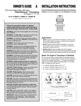
Installation in a Cored Fiberglass Hull
The core (wood or foam) must be cut and sealed carefully. The
core must be protected from water seepage, and the hull must be
reinforced to prevent it from crushing under the hull nut allowing
the housing to become loose.
CAUTION: Completely seal the hull to prevent water seepage into
the core.
1. Drill a 3mm or 1/8" pilot hole from inside the hull. If there is a rib,
strut, or other hull irregularity near the selected mounting
location, drill from the outside. (If the hole is drilled in the wrong
location, drill a second hole in a better location. Apply masking
tape to the outside of the hull over the incorrect hole and fill it
with epoxy.)
2. Using a 51mm or 2" hole saw, cut the hole from outside the hull
through the outer skin only (Figure 4).
3. From inside the hull, use a 60mm or 2-3/8" hole saw to cut
through the inner skin and most of the core. The core material
can be very soft. Apply only light pressure to the hole saw after
cutting through the inner skin to avoid accidentally cutting the
outer skin.
4. Remove the plug of core material so the inside of the outer skin
and the inner core of the hull are fully exposed. Sand and clean
the inner skin, core, and the outer skin around the hole.
5. If you are skilled with fiberglass, saturate a layer of fiberglass
cloth with a suitable resin and lay it inside the hole to seal and
strengthen the core. Add layers until the hole is the correct
diameter.
Alternatively, a hollow or solid cylinder of the correct diameter
can be coated with wax and taped in place. Fill the gap between
the cylinder and hull with casting epoxy. After the epoxy has set,
remove the cylinder.
6. Sand and clean the area around the hole, inside and outside, to
ensure that the marine sealant will adhere properly to the hull. If
there is any petroleum residue inside the hull, remove it with
either mild household detergent or a weak solvent (alcohol)
before sanding.
7. Proceed with “Bedding” (page 3).
.Operation, Maintenance & Parts
How the Valve Works
THE VALVE IS NOT A WATERTIGHT SEAL! The sensor
incorporates a self-closing valve which minimizes the flow of
water into the boat when the insert is removed. The curved flap
valve is activated by both a spring and water pressure. Water
pushes the flap valve upward to block the opening, so there is no
gush of water into the boat. Always install the insert or the
blanking plug secured with the cap nut and safety wire for a
watertight seal.
Using the Blanking Plug
To protect the paddlewheel, use the blanking plug:
When the boat will be kept in salt water for more than a week.
When the boat will be removed from the water.
When aquatic growth buildup on the paddlewheel is suspected
due to inaccurate readings from the instrument.
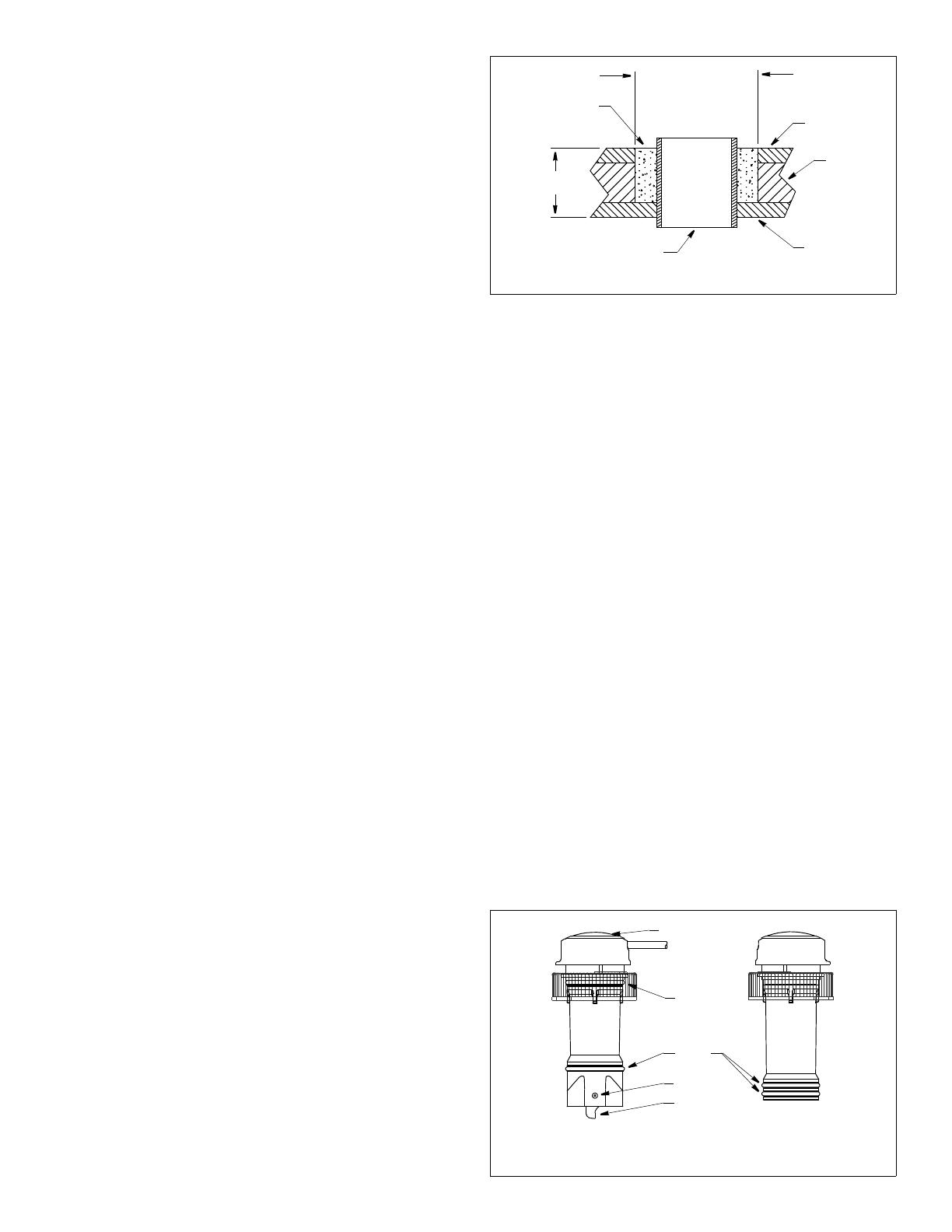
1. The O-rings must be intact and well lubricated to make a
watertight seal. On the blanking plug, inspect the O-rings
(replace if necessary) and lubricate them with the silicone
lubricant supplied or petroleum jelly (Figure 5).
2. Remove the insert from the housing by removing the safety wire
and unscrewing the cap nut (Figure 3). This will jack up the
insert. Remove the insert with a slow pulling motion. Replace it
by sliding the blanking plug into the housing.
NOTE: In the very unlikely event that the valve breaks, replace
the housing the next time the boat is hauled.
3. With the blanking plug fully inserted, screw the cap nut several
turns until the threads are engaged. Continue to tighten the cap
nut completely. Hand tighten only. Do not over tighten.
Figure 4. Preparing a cored fiberglass hull
inner skin
core
outer skin
solid or hollow cylinder
pour in
casting
epoxy
9-12 mm
(3/8- 1/2")
larger than the
hole through the
hull’s outer skin
hull thickness
Copyright © 2005 Airmar Technology Corp
Figure 5. Replacing the paddlewheel and O-rings
arrow
flat side
of blade
shaft
blanking
insert
faces bow
yellow
O-ring
small
O-ring(s)
Copyright © 2005 Airmar Technology Corp
BOW
plug
4
5
NOTE: The blanking plug must be fully inserted in the housing
and the cap nut screwed on completely for a watertight seal.
4. Reattach the safety wire to prevent the blanking plug from
backing out in the unlikely event that the cap nut fails or is
screwed on incorrectly.
Winterizing
After the boat has been hauled for winter storage, remove the
blanking plug to let the water drain away before reinserting it. This
will prevent any water from freezing around the blanking plug,
possibly cracking the plastic.
Servicing the Insert
Aquatic growth can accumulate rapidly on the depth transducer’s
face and impede or freeze the paddlewheel’s rotation reducing
performance within weeks. Clean the insert with a Scotch-Brite®
scour pad and mild household detergent, being careful to avoid
scratching the depth transducer. If fouling is severe, remove the
paddlewheel (see step #1 below). Lightly wet sand it with fine
grade wet/dry paper.
The water lubricated paddlewheel bearings have a life of up to 5
years on low-speed boats [less than 10kn (11MPH)] and 1 year
on high-speed vessels. Paddlewheels can fracture and shafts can
bend due to impact with water borne objects and mishandling in
boat yards. O-rings must be free of abrasions and cuts to ensure
a watertight seal.
1. To remove the old paddlewheel shaft, grasp the end with small
diagonal wire cutters and pull (Figure 5).
2. Place the new paddlewheel in the cavity with the flat side of the
blade facing the same direction as the arrow on the top of the
insert.
3. Tap the new shaft into place until the end is flush with the
outside wall of the insert.
4. Install the yellow O-ring near the top of the insert. Install a small
O-ring near the paddlewheel.
5. Place the remaining two small O-rings near the bottom of the
blanking plug.
Replacement Sensor & Parts
The information needed to order a replacement Airmar sensor is
printed on the cable tag. Do not remove this tag. When ordering,
specify the part number, date, and frequency in kHz. For convenient
reference, record this information on the top of page one.
Lost, broken, or worn parts should be replaced immediately. If you
have purchased a plastic housing and have a wood hull or desire
greater strength, purchase an Airmar metal housing. Obtain parts
from your instrument manufacturer or marine dealer.
Gemeco USA
Tel: 803-693-0777
Airmar EMEA Europe, Middle East, Africa
Tel: +33.(0)2.23.52.06.48
Email: sales@airmar-emea.com
DST810—CAST App
Download the CAST app by Airmar to view, analyze, and share
sensor data and evaluate your boat’s performance. Install the
CAST app on your iOS or Android device to view available NMEA
data over a wireless or network connection (Figure 6).
With the CAST app you can perform depth, speed, temperature,
and attitude calibrations. Smart devices with Bluetooth®
connectivity can be used to view the data. Within the Cast App,
you can link to and download the CAST App User Guide.
Downloading the CAST App
1. Go to the App Store or Google Play Store.
2. Search on the word Airmar.
3. Download the free CAST app
Figure 6. Connecting the DST810 to the network and the CAST app
Copyright© 2020 Airmar Technology Corporation
wireless connection
6Copyright © 2005 - 2020 Airmar Technology Corp. All rights reserved.
35 Meadowbrook Drive, Milford, New Hampshire 03055-4613, USA
www.airmar.com
  • Page 1 1
  • Page 2 2
  • Page 3 3
  • Page 4 4
  • Page 5 5
  • Page 6 6

Airmar DST800 Owner's manual

Type
Owner's manual

Airmar DST800 is a multisensor device that combines depth, speed, and temperature readings into one compact and versatile package. Its robust design and ease of installation make it a popular choice for boaters of all levels. With its retractable thru-hull design, the DST800 can be easily installed in a variety of hull types, including fiberglass, metal, and wood.

Ask a question and I''ll find the answer in the document

Finding information in a document is now easier with AI