
BladeCenter HS23 Blade Server
Problem Determination and Service Guide
Machine Types: 7875, 1929

Note
Before using this information and the product it supports, read the general information in Appendix B
“Notices” on page 269, the Warranty Information document, and the IBM Safety Information and the
Environmental Notices and User Guide documents on the IBM Documentation CD.
The most recent version of this document is available at http://www.ibm.com/supportportal/.
Eightieth Edition (May 2015)
© Copyright Lenovo 2014, 2015.
LIMITED AND RESTRICTED RIGHTS NOTICE: If data or software is delivered pursuant a General Services
Administration “GSA” contract, use, reproduction, or disclosure is subject to restrictions set forth in Contract No.
GS-35F-05925

Contents
Safety . . . . . . . . . . . . . . . . . . iii
Guidelines for trained technicians . . . . . . . . . iv
Inspecting for unsafe conditions . . . . . . . iv
Guidelines for servicing electrical equipment. . . v
Safety statements . . . . . . . . . . . . . . . vi
Start here . . . . . . . . . . . . . . . . . . xi
Diagnosing a problem . . . . . . . . . . . xi
Undocumented problems . . . . . . . . . xiv
Chapter 1. Introduction . . . . . . . . . 1
Related documentation . . . . . . . . . . . . . 1
Notices and statements in this document. . . . . . 2
Features and specifications . . . . . . . . . . . 2
Blade server controls and LEDs . . . . . . . . . 4
Turning on the blade server . . . . . . . . . . . 6
Turning off the blade server . . . . . . . . . . . 7
Blade server system-board layouts . . . . . . . . 7
Blade server connectors . . . . . . . . . . 7
System-board switch . . . . . . . . . . . . 8
System-board LEDs . . . . . . . . . . . . 9
Chapter 2. Configuring the blade
server. . . . . . . . . . . . . . . . . . 11
Using the Setup utility . . . . . . . . . . . . 11
Setup utility menu . . . . . . . . . . . . 12
Using passwords . . . . . . . . . . . . 15
Using the Boot Menu program . . . . . . . 15
Updating the Universal Unique Identifier
(UUID). . . . . . . . . . . . . . . . . 16
Updating the DMI/SMBIOS data . . . . . . 18
Using the ServerGuide Setup and Installation
CD . . . . . . . . . . . . . . . . . . . . 21
ServerGuide features . . . . . . . . . . . 21
Setup and configuration overview . . . . . . 22
Installing the operating system . . . . . . . 22
Setting the PXE boot protocol using the Setup
utility . . . . . . . . . . . . . . . . . . . 23
Updating firmware and device drivers . . . . . . 23
Configuring UEFI compatible devices . . . . . . 24
Configuring the Gigabit Ethernet controller . . . . 25
Configuring a RAID array . . . . . . . . . . . 25
Using LAN over USB to interface the IMM2 . . . . 25
Potential conflicts with the LAN over USB
interface . . . . . . . . . . . . . . . . 26
Resolving conflicts with the IMM2 LAN over
USB interface . . . . . . . . . . . . . . 26
Configuring the LAN over USB interface
manually. . . . . . . . . . . . . . . . 27
Chapter 3. Parts listing . . . . . . . . 29
Parts listing, Types 7875 and 1929 . . . . . . . 29
Consumable and structural parts . . . . . . . . 36
Chapter 4. Removing and replacing
blade server components . . . . . . . 37
Installation guidelines . . . . . . . . . . . . 37
System reliability guidelines . . . . . . . . 38
Handling static-sensitive devices . . . . . . 38
Returning a device or component . . . . . . 38
Removing the blade server from the BladeCenter
unit. . . . . . . . . . . . . . . . . . . . 39
Installing the blade server in a BladeCenter unit . . 39
Removing and replacing Tier 1 customer
replaceable units (CRUs) . . . . . . . . . . . 41
Removing the battery. . . . . . . . . . . 41
Installing the battery . . . . . . . . . . . 42
Removing a hot-swap storage drive . . . . . 44
Installing a hot-swap storage drive . . . . . 44
Removing a memory module . . . . . . . . 45
Installing a memory module . . . . . . . . 47
Removing a USB Flash key . . . . . . . . 49
Installing a USB Flash key . . . . . . . . . 50
Removing an I/O expansion card . . . . . . 50
Installing an I/O expansion card. . . . . . . 53
Removing the control panel . . . . . . . . 55
Installing the control panel . . . . . . . . . 56
Removing a blade handle . . . . . . . . . 57
Installing a blade handle. . . . . . . . . . 57
Removing and replacing Tier 2 customer
replaceable units (CRUs) . . . . . . . . . . . 58
Removing an optional expansion unit . . . . 58
Installing an optional expansion unit . . . . . 59
Removing a microprocessor and heat sink . . 61
Installing a microprocessor and heat sink . . . 65
Thermal grease . . . . . . . . . . . . . 70
Removing the system-board assembly . . . . 71
Installing the system-board assembly . . . . 71
Removing and replacing consumable and
structural parts . . . . . . . . . . . . . . . 72
Removing the blade server cover . . . . . . 72
Installing the blade server cover. . . . . . . 73
Removing the bezel assembly . . . . . . . 74
Installing the bezel assembly . . . . . . . . 75
Chapter 5. Diagnostics . . . . . . . . 77
© Copyright Lenovo 2014, 2015 i

Service bulletins . . . . . . . . . . . . . . 77
Checkout procedure . . . . . . . . . . . . . 77
About the checkout procedure . . . . . . . 77
Performing the checkout procedure . . . . . 78
Diagnostic tools overview . . . . . . . . . . . 78
Event logs . . . . . . . . . . . . . . . . . 79
Viewing event logs through the Setup utility . . 79
Viewing event logs without restarting the
blade server . . . . . . . . . . . . . . 80
POST . . . . . . . . . . . . . . . . . . . 81
POST/UEFI diagnostic codes . . . . . . . . . 81
IMM error messages . . . . . . . . . . . . . 105
Troubleshooting tables . . . . . . . . . . . . 188
General problems . . . . . . . . . . . . 188
Hard disk drive problems . . . . . . . . . 189
Intermittent problems. . . . . . . . . . . 190
Keyboard or mouse problems . . . . . . . 190
Memory problems . . . . . . . . . . . . 191
Monitor or video problems . . . . . . . . . 192
Network connection problems . . . . . . . 193
Optional-device problems . . . . . . . . . 194
Power error messages . . . . . . . . . . 195
Power problems. . . . . . . . . . . . . 198
Removable-media drive problems . . . . . . 200
ServerGuide problems . . . . . . . . . . 201
Service processor problems . . . . . . . . 202
Software problems. . . . . . . . . . . . 202
Universal Serial Bus (USB) port problems . . . 203
Light path diagnostics . . . . . . . . . . . . 204
Viewing the light path diagnostics LEDs in the
blade server . . . . . . . . . . . . . . 204
Blade server light path diagnostics LEDs . . . 205
IBM Dynamic System Analysis Preboot diagnostic
program. . . . . . . . . . . . . . . . . . 209
Running the diagnostic programs . . . . . . 209
Diagnostic text messages . . . . . . . . . 210
Viewing the test results . . . . . . . . . . 211
Diagnostic messages. . . . . . . . . . . 211
IMM self tests . . . . . . . . . . . . . . . 211
Emulex Ethernet device tests . . . . . . . . . 233
CPU stress tests . . . . . . . . . . . . . . 235
Memory self tests . . . . . . . . . . . . . . 237
Optical drive self tests . . . . . . . . . . . . 248
Storage drive self tests . . . . . . . . . . . . 252
Tape alert flags . . . . . . . . . . . . . . . 253
Recovering from a UEFI update failure . . . . . . 254
In-band manual recovery method . . . . . . 254
Out-of-band manual recovery method . . . . 255
In-band automated boot recovery method . . 256
Out-of-band automated boot recovery
method . . . . . . . . . . . . . . . . 257
Automated boot recovery (ABR) . . . . . . . . 257
Nx boot failure . . . . . . . . . . . . . . . 258
Service processor (IMM) error codes . . . . . . 258
Solving SAS hard disk drive problems . . . . . . 258
Solving shared BladeCenter resource
problems . . . . . . . . . . . . . . . . . 258
Keyboard or mouse problems . . . . . . . 259
Media tray problems . . . . . . . . . . . 259
Network connection problems . . . . . . . 261
Power problems . . . . . . . . . . . . . 261
Video problems . . . . . . . . . . . . . 262
Solving undetermined problems . . . . . . . . 262
Problem determination tips . . . . . . . . . . 264
Appendix A. Getting help and
technical assistance . . . . . . . . . . 265
Before you call . . . . . . . . . . . . . . . 265
Using the documentation . . . . . . . . . . . 266
Getting help and information from the World Wide
Web . . . . . . . . . . . . . . . . . . . 266
How to send DSA data to IBM . . . . . . . . . 266
Creating a personalized support web page . . . . 266
Software service and support . . . . . . . . . 266
Hardware service and support . . . . . . . . . 267
Taiwan import and export contact information . . . 267
Appendix B. Notices. . . . . . . . . . 269
Trademarks . . . . . . . . . . . . . . . . 269
Important notes . . . . . . . . . . . . . . . 270
Particulate contamination . . . . . . . . . . . 270
Documentation format . . . . . . . . . . . . 271
Telecommunication regulatory statement. . . . . 272
Electronic emission notices . . . . . . . . . . 272
Taiwan BSMI RoHS declaration. . . . . . . 273
Index . . . . . . . . . . . . . . . . . . 275
ii BladeCenter HS23 Blade ServerProblem Determination and Service Guide

Safety
Before installing this product, read the Safety Information.
Antes de instalar este produto, leia as Informações de Segurança.
Læs sikkerhedsforskrifterne, før du installerer dette produkt.
Lees voordat u dit product installeert eerst de veiligheidsvoorschriften.
Ennen kuin asennat tämän tuotteen, lue turvaohjeet kohdasta Safety Information.
Avant d'installer ce produit, lisez les consignes de sécurité.
Vor der Installation dieses Produkts die Sicherheitshinweise lesen.
Prima di installare questo prodotto, leggere le Informazioni sulla Sicurezza.
Les sikkerhetsinformasjonen (Safety Information) før du installerer dette produktet.
Antes de instalar este produto, leia as Informações sobre Segurança.
© Copyright Lenovo 2014, 2015 iii

Antes de instalar este producto, lea la información de seguridad.
Läs säkerhetsinformationen innan du installerar den här produkten.
Guidelines for trained technicians
This section contains information for trained technicians.
Inspecting for unsafe conditions
Use this information to help you identify potential unsafe conditions in an IBM product that you are working
on.
Each IBM product, as it was designed and manufactured, has required safety items to protect users and
service technicians from injury. The information in this section addresses only those items. Use good
judgment to identify potential unsafe conditions that might be caused by non-IBM alterations or attachment
of non-IBM features or optional devices that are not addressed in this section. If you identify an unsafe
condition, you must determine how serious the hazard is and whether you must correct the problem before
you work on the product.
Consider the following conditions and the safety hazards that they present:
• Electrical hazards, especially primary power. Primary voltage on the frame can cause serious or fatal
electrical shock.
• Explosive hazards, such as a damaged CRT face or a bulging capacitor.
• Mechanical hazards, such as loose or missing hardware.
To inspect the product for potential unsafe conditions, complete the following steps:
1. Make sure that the power is off and the power cords are disconnected.
2. Make sure that the exterior cover is not damaged, loose, or broken, and observe any sharp edges.
3. Check the power cords:
• Make sure that the third-wire ground connector is in good condition. Use a meter to measure third-
wire ground continuity for 0.1 ohm or less between the external ground pin and the frame ground.
• Make sure that the power cords are the correct type.
• Make sure that the insulation is not frayed or worn.
iv
BladeCenter HS23 Blade ServerProblem Determination and Service Guide

4. Remove the cover.
5. Check for any obvious non-IBM alterations. Use good judgment as to the safety of any non-IBM
alterations.
6. Check inside the system for any obvious unsafe conditions, such as metal filings, contamination, water
or other liquid, or signs of fire or smoke damage.
7. Check for worn, frayed, or pinched cables.
8. Make sure that the power-supply cover fasteners (screws or rivets) have not been removed or tampered
with.
Guidelines for servicing electrical equipment
Observe these guidelines when you service electrical equipment.
• Check the area for electrical hazards such as moist floors, nongrounded power extension cords, and
missing safety grounds.
• Use only approved tools and test equipment. Some hand tools have handles that are covered with a soft
material that does not provide insulation from live electrical current.
• Regularly inspect and maintain your electrical hand tools for safe operational condition. Do not use worn
or broken tools or testers.
• Do not touch the reflective surface of a dental mirror to a live electrical circuit. The surface is conductive
and can cause personal injury or equipment damage if it touches a live electrical circuit.
• Some rubber floor mats contain small conductive fibers to decrease electrostatic discharge. Do not use
this type of mat to protect yourself from electrical shock.
• Do not work alone under hazardous conditions or near equipment that has hazardous voltages.
• Locate the emergency power-off (EPO) switch, disconnecting switch, or electrical outlet so that you can
turn off the power quickly in the event of an electrical accident.
• Disconnect all power before you perform a mechanical inspection, work near power supplies, or remove
or install main units.
• Before you work on the equipment, disconnect the power cord. If you cannot disconnect the power cord,
have the customer power-off the wall box that supplies power to the equipment and lock the wall box in
the off position.
• Never assume that power has been disconnected from a circuit. Check it to make sure that it has been
disconnected.
• If you have to work on equipment that has exposed electrical circuits, observe the following precautions:
– Make sure that another person who is familiar with the power-off controls is near you and is available to
turn off the power if necessary.
– When you work with powered-on electrical equipment, use only one hand. Keep the other hand in your
pocket or behind your back to avoid creating a complete circuit that could cause an electrical shock.
– When you use a tester, set the controls correctly and use the approved probe leads and accessories for
that tester.
– Stand on a suitable rubber mat to insulate you from grounds such as metal floor strips and equipment
frames.
• Use extreme care when you measure high voltages.
• To ensure proper grounding of components such as power supplies, pumps, blowers, fans, and motor
generators, do not service these components outside of their normal operating locations.
• If an electrical accident occurs, use caution, turn off the power, and send another person to get medical
aid.
© Copyright Lenovo 2014, 2015 v

Safety statements
These statements provide the caution and danger information that is used in this documentation.
Important: Each caution and danger statement in this documentation is labeled with a number. This number
is used to cross reference an English-language caution or danger statement with translated versions of the
caution or danger statement in the Safety Information document.
For example, if a caution statement is labeled “Statement 1,” translations for that caution statement are in the
Safety Information document under “Statement 1.”
Be sure to read all caution and danger statements in this documentation before you perform the procedures.
Read any additional safety information that comes with your system or optional device before you install the
device.
Statement 1
DANGER
Electrical current from power, telephone, and communication cables is hazardous.
To avoid a shock hazard:
• Do not connect or disconnect any cables or perform installation, maintenance, or reconfiguration
of this product during an electrical storm.
• Connect all power cords to a properly wired and grounded electrical outlet.
• Connect to properly wired outlets any equipment that will be attached to this product.
• When possible, use one hand only to connect or disconnect signal cables.
• Never turn on any equipment when there is evidence of fire, water, or structural damage.
• Disconnect the attached power cords, telecommunications systems, networks, and modems
before you open the device covers, unless instructed otherwise in the installation and
configuration procedures.
• Connect and disconnect cables as described in the following table when installing, moving, or
opening covers on this product or attached devices.
To Connect: To Disconnect:
1. Turn everything OFF.
2. First, attach all cables to devices.
3. Attach signal cables to connectors.
4. Attach power cords to outlet.
5. Turn device ON.
1. Turn everything OFF.
2. First, remove power cords from outlet.
3. Remove signal cables from connectors.
4. Remove all cables from devices.
vi BladeCenter HS23 Blade ServerProblem Determination and Service Guide

Statement 2
CAUTION:
When replacing the lithium battery, use only IBM Part Number 33F8354 or an equivalent type battery
recommended by the manufacturer. If your system has a module containing a lithium battery, replace
it only with the same module type made by the same manufacturer. The battery contains lithium and
can explode if not properly used, handled, or disposed of.
Do not:
• Throw or immerse into water
• Heat to more than 100°C (212°F)
• Repair or disassemble
Dispose of the battery as required by local ordinances or regulations.
Statement 3
CAUTION:
When laser products (such as CD-ROMs, DVD drives, fiber optic devices, or transmitters) are
installed, note the following:
• Do not remove the covers. Removing the covers of the laser product could result in exposure to
hazardous laser radiation. There are no serviceable parts inside the device.
• Use of controls or adjustments or performance of procedures other than those specified herein
might result in hazardous radiation exposure.
DANGER
Some laser products contain an embedded Class 3A or Class 3B laser diode. Note the following.
Laser radiation when open. Do not stare into the beam, do not view directly with optical
instruments, and avoid direct exposure to the beam.
Class 1 Laser Product
Laser Klasse 1
Laser Klass 1
Luokan 1 Laserlaite
Appareil A Laser de Classe 1
`
© Copyright Lenovo 2014, 2015 vii

Statement 4
≥ 18 kg (39.7 lb) ≥ 32 kg (70.5 lb) ≥ 55 kg (121.2 lb)
CAUTION:
Use safe practices when lifting.
Statement 8
CAUTION:
Never remove the cover on a power supply or any part that has the following label attached.
Hazardous voltage, current, and energy levels are present inside any component that has this label
attached. There are no serviceable parts inside these components. If you suspect a problem with one
of these parts, contact a service technician.
Statement 12
CAUTION:
The following label indicates a hot surface nearby.
viii BladeCenter HS23 Blade ServerProblem Determination and Service Guide

Statement 13
DANGER
Overloading a branch circuit is potentially a fire hazard and a shock hazard under certain
conditions. To avoid these hazards, ensure that your system electrical requirements do not exceed
branch circuit protection requirements. Refer to the information that is provided with your device
for electrical specifications.
Statement 21
CAUTION:
Hazardous energy is present when the blade is connected to the power source. Always replace the
blade cover before installing the blade.
Statement 32
CAUTION:
To avoid personal injury, before lifting the unit, remove all the blades, power supplies, and removable
modules to reduce the weight.
108 kg
(237 lbs)
(2X)
(6X)
(4X)
(4X)
43.2 kg
(95 lbs)
Statement 33
CAUTION:
This device does not provide a power control button. Removing power supply modules or turning off
the server blades does not turn off the electrical current supplied to the device. The device also might
have more than one power cord. To remove all electrical current from the device, ensure that all
power cords are disconnected from the power source.
© Copyright Lenovo 2014, 2015 ix

Rack Safety Information, Statement 2
DANGER
• Always lower the leveling pads on the rack cabinet.
• Always install stabilizer brackets on the rack cabinet.
• Always install servers and optional devices starting from the bottom of the rack cabinet.
• Always install the heaviest devices in the bottom of the rack cabinet.
UL regulatory information
This device is for use only with supported blade chassis.
x
BladeCenter HS23 Blade ServerProblem Determination and Service Guide

Start here
You can solve many problems without outside assistance by following the troubleshooting procedures in this
documentation and on the IBM Web site.
This Problem Determination and Service Guide describes the diagnostic tests that you can perform,
troubleshooting procedures, and explanations of error messages and error codes. The documentation that
comes with your operating system and software also contains troubleshooting information.
Diagnosing a problem
Before you contact IBM or an approved warranty service provider, follow these procedures in the order in
which they are presented to diagnose a problem with your blade server.
Step 1. Determine what has changed.
Determine whether any of the following items were added, removed, replaced, or updated before
the problem occurred:
• Unified Extensible Firmware Interface (UEFI) code
• Device drivers
• Firmware
• Hardware components
• Software
If possible, return the blade server to the condition it was in before the problem occurred.
Step 2. Collect data.
Thorough data collection is necessary for diagnosing hardware and software problems.
Note: Event messages that include links to descriptions and recommended actions can be viewed
in the advanced management module event log (see the Advanced Management Module User's
Guide for additional information). A listing of all general event information is in the BladeCenter
Advanced Management Module Messages Guide.
a. Document error codes and light path diagnostics LEDs.
• System error codes: See “Event logs” on page 79 for information about a specific error
code.
• Software or operating-system error codes: See the documentation for the software or
operating system for information about a specific error code. See the manufacturer's Web
site for documentation.
• Light path diagnostics LEDs: See “Light path diagnostics” on page 204 for information
about LEDs that are lit.
b. Collect system data.

Run Dynamic System Analysis (DSA) to collect information about the hardware, firmware,
software, and operating system. Have this information available when you contact IBM or an
approved warranty service provider. To download the latest version of DSA, go to http://www.
ibm.com/ support/entry/portal/docdisplay? brand=5000008&lndocid=SERV-DSA.
For information about DSA command-line options, go to http://publib.boulder.ibm.com/
infocenter/toolsctr/v1r0/index.jsp? topic=/dsa/dsa_main.html.
c. Collect BladeCenter unit data.
Data about the BladeCenter unit is available through the Advanced-Management-Module Web
interface. Have this information available when you contact IBM or an approved warranty
service provider. You can view the information or save it as a compressed package, named
Service Data, that you can transfer to another system or provide to a service representative.
For information about saving the Service Data file, see the Advanced-Management-Module
User's Guide at http://www.ibm.com/ support/entry/portal/docdisplay? brand=
5000008&lndocid=MIGR-5073887.
Step 3. Follow the problem-resolution procedures.
The four problem-resolution procedures are presented in the order in which they are most likely to
solve your problem. Follow these procedures in the order in which they are presented:
1. Check for and apply code updates.
Most problems that appear to be caused by faulty hardware are actually caused by UEFI code,
system firmware, device firmware, or device drivers that are not at the latest levels.
a. Determine the existing code levels.
• In DSA, click Firmware/VPD to view system firmware levels, or click Software to view
operating-system levels.
• In the navigation pane of the Advanced-Management-Module Web interface, click
Monitors and click Firmware VPD to view the firmware levels in the blade servers and
management module.
b. Download and install updates of code that is not at the latest level.
To display a list of available updates for your blade server, go to http://www.ibm.com/
support/ fixcentral/systemx/groupView? query.productGroup=ibm%2FBladeCenter.
You can install code updates that are packaged as an IBM UpdateXpress System Pack or
UpdateXpress CD image. An UpdateXpress System Pack contains an integration-tested
bundle of online firmware and device-driver updates for your blade server.
Be sure to install any listed critical updates that have release dates that are later than the
release date of the UpdateXpress System Pack or UpdateXpress image.
When you click an update, an information page is displayed, including a list of the problems
that the update fixes. Review this list for your specific problem; however, even if your
problem is not listed, installing the update might solve the problem.
Step 4. Check for and correct an incorrect configuration.

If the blade server is incorrectly configured, a system function can fail to work when you enable it; if
you make an incorrect change to the blade server configuration, a system function that has been
enabled can stop working.
1. Make sure that all installed hardware and software are supported.
See http://www.ibm.com /systems/info/x86servers/ serverproven/compat/us/ to verify that the
blade server supports the installed operating system, optional devices, and software levels. If
any hardware or software component is not supported, uninstall it to determine whether it is
causing the problem. You must remove nonsupported hardware before you contact IBM or an
approved warranty service provider for support.
2. Make sure that the blade server, operating system, and software are installed and
configured correctly.
Many configuration problems are caused by loose power or signal cables or incorrectly seated
adapters. You might be able to solve the problem by turning off the blade server, reconnecting
cables, reseating adapters, and turning the blade server back on.
If the problem is associated with a specific function (for example, if a RAID hard disk drive is
marked offline in the RAID array), see the documentation for the associated controller and
management or controlling software to verify that the controller is correctly configured.
Problem determination information is available for many devices such as RAID and network
adapters.
For problems with operating systems or IBM software or devices, go to http://www.ibm.com/
supportportal/.
Step 5. Check for service bulletins.
IBM service bulletins document known problems and suggested solutions. To search for service
bulletins, go to http://www.ibm.com/supportportal/.complete the following steps.
Step 6. Check for and replace defective hardware.
If a hardware component is not operating within specifications, it can cause unpredictable results.
Most hardware failures are reported as error codes in a system or operating-system log. Hardware
errors are also indicated by light path diagnostics LEDs.
Troubleshooting procedures are provided on the IBM Web site. A single problem might cause
multiple symptoms. Follow the diagnostic procedure for the most obvious symptom. If that
procedure does not diagnose the problem, use the procedure for another symptom, if possible. To
locate troubleshooting procedures for your server, go to http://www.ibm.com/supportportal/.
If the problem remains, contact IBM or an approved warranty service provider for assistance with
additional problem determination and possible hardware replacement. To open an online service
request, go to http://www.ibm.com/support/electronic/portal/. Be prepared to provide information
about any error codes and collected data.

Undocumented problems
If you have completed the diagnostic procedure and the problem remains, the problem might not have been
previously identified by IBM. After you have verified that all code is at the latest level, all hardware and
software configurations are valid, and no light path diagnostics LEDs or log entries indicate a hardware
component failure, contact IBM or an approved warranty service provider for assistance.
To open an online service request, go to http://www.ibm.com/support/electronic/portal/. Be prepared to
provide information about any error codes and collected data and the problem determination procedures
that you have used.

Chapter 1. Introduction
Use this information to help you solve problems that might occur in your blade server.
This Problem Determination and Service Guide contains information to help you solve problems that might
occur in your IBM BladeCenter HS23 Type 7875 or 1929 blade server. It describes the diagnostic tools that
come with the blade server, error codes and suggested actions, and instructions for replacing failing
components.
Replaceable components consist of consumable parts, structural parts, and customer replaceable units
(CRUs):
• Consumables: Purchase and replacement of consumables (components, such as batteries and printer
cartridges, that have depleting life) is your responsibility. If IBM acquires or installs a consumable
component at your request, you will be charged for the service.
• Structural parts: Purchase and replacement of structural parts (components, such as chassis assembly,
top cover, and bezel) is your responsibility. If IBM acquires or installs a structural component at your
request, you will be charged for the service.
• Customer replaceable unit (CRU):
– Tier 1 customer replaceable unit: Replacement of Tier 1 CRUs is your responsibility. If IBM installs a
Tier 1 CRU at your request, you will be charged for the installation.
– Tier 2 customer replaceable unit: You may install a Tier 2 CRU yourself or request IBM to install it, at
no additional charge, under the type of warranty service that is designated for your server. Some tier 2
CRUs must be installed only by trained technicians.
See Chapter 3 “Parts listing” on page 29 to determine whether a component is a consumable, structural, or
customer replaceable unit.
For information about the terms of the warranty and getting service and assistance, see the Warranty
Information document.
Related documentation
Use this information to identify and locate related blade server documentation.
This Problem Determination and Service Guide contains information to help you solve problems yourself,
how to remove and install components, and it contains information for service technicians. The following
documentation is also available:
• Safety Information
This document contains translated caution and danger statements. Each caution and danger statement
that appears in the documentation has a number that you can use to locate the corresponding statement
in your language in the Safety Information document.
• Warranty Information
This document contains information about the terms of the warranty.
• Environmental Notices and User Guide
This document contains translated environmental notices.
• Integrated Management Module II User's Guide
© Copyright Lenovo 2014, 2015 1

This document explains how to use the functions of the IMM2 that is installed in an IBM server. The IMM2
works with IBM UEFI firmware to provide systems-management capability for System x® servers and
blade servers.
• Advanced Management Module Messages Guide
This document provides a complete list of all non-device specific events and recommended actions,
sorted by event ID. Device specific event information is in the documentation for the device.
• Advanced Management Module Command-Line Interface Reference Guide
This document explains how to use the advanced management module command-line interface (CLI) to
directly access the BladeCenter management functions. The command-line interface also provides
access to the text-console command prompt on each blade server through a Serial over LAN (SOL)
connection.
• Advanced Management Module Messages Guide
This document provides a complete list of all non-device-specific events and recommended actions,
sorted by event ID. For event information that is specific to this blade server, see “IMM error messages”
on page 105 for more information.
• Safety Labels
This document is in PDF on the IBM System x Documentation CD. This document provides the Simplified
Chinese, Mongolian, Tibetan, Uygur, and Zhuang translated versions of the product safety labels.
In addition to the documentation in this library, be sure to review the Planning and Installation Guide for your
BladeCenter unit for information to help you prepare for system installation and configuration.
To check for updated documentation and technical updates, go to http://www.ibm.com/supportportal/.
Notices and statements in this document
Use this information to understand the most common documentation notices and statements and how they
are used.
The caution and danger statements in this document are also in the multilingual Safety Information
document, which is on the IBMDocumentation CD. Each statement is numbered for reference to the
corresponding statement in the Safety Information document.
The following notices and statements are used in this document:
• Note: These notices provide important tips, guidance, or advice.
• Important: These notices provide information or advice that might help you avoid inconvenient or
problem situations.
• Attention: These notices indicate possible damage to programs, devices, or data. An attention notice is
placed just before the instruction or situation in which damage might occur.
• Caution: These statements indicate situations that can be potentially hazardous to you. A caution
statement is placed just before the description of a potentially hazardous procedure step or situation.
• Danger: These statements indicate situations that can be potentially lethal or extremely hazardous to you.
A danger statement is placed just before the description of a potentially lethal or extremely hazardous
procedure step or situation.
Features and specifications
Use this table to view specific information about the blade server, such as blade server hardware features
and the dimensions of the blade server.
2
BladeCenter HS23 Blade ServerProblem Determination and Service Guide

Notes:
1. Power, cooling, removable-media drives, external ports, and advanced system management are
provided by the BladeCenter unit.
2. The operating system in the blade server must provide USB support for the blade server to recognize
and use USB media drives and devices. The BladeCenter unit uses USB for internal communications
with these devices.
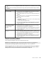
The following table is a summary of the features and specifications of the blade server.
Table 1. Features and specifications
Microprocessor: Supports up to two
multi-core IntelXeon
microprocessors.
Note: Use the Setup utility to
determine the type and speed of the
microprocessors in the blade server.
Memory:
• 16 dual inline memory module
(DIMM) connectors
• Type: Very Low Profile (VLP)
double-data rate (DDR3) DRAM.
Supports 4 GB, 8 GB, and 16 GB
DIMMs with up to 256 GB of total
memory on the system board
Integrated functions:
• Horizontal-compact-form-factor
(CFFh) expansion card interface
• Vertical-combination-I/O (CIOv)
expansion card interface
• Local service processor:
Integrated Management Module II
(IMM2) with Intelligent Platform
Management Interface (IPMI)
firmware
• Integrated Renesas SH7757 IMM2
video controller
• SAS controller
• Integrated keyboard/video/mouse
(cKVM) controller through IMM2
• Light path diagnostics
• RS-485 interface for
communication with the
management module
• USB 2.0 for communication with
cKVM and removable media drives
(an external USB port is not
supported)
• Serial over LAN (SOL)
• Wake on LAN (WOL)
• Redundant buses for
communication with keyboard,
mouse, and removable media
drives
Predictive Failure Analysis (PFA)
alerts:
• Microprocessors
• Memory
• Storage drives
Electrical input: 12 V dc
Environment:
• Air temperature:
– Blade server on: 10°C to 35°C
(50°F to 95°F). Altitude: 0 m to
914.4 m (0 ft to 3000 ft)
– Blade server on: 10°C to 32°C
(50°F to 89.6°F). Altitude:
914.4 m to 2133.6 m (3000 ft
to 7000 ft)
– Blade server off: 10°C to 43°C
(50°F to 109.4°F). Altitude:
914.4 m to 2133.6 m (3000 ft
to 7000 ft)
– Blade server shipping: -40°C
to 60°C (-40°F to 140°F)
• Humidity:
– Blade server on: 8% to 80%
– Blade server off: 8% to 80%
– Blade server storage: 5% to
80%
– Blade server shipment: 5% to
100%
• E5-2697 V2 and E5-2690 V2 will
reach their maximum operating
temperature and throttle at
ambient 31°C in Blade Center H
chassis, when being fully
exercised.
Drives: Supports up to two hot-swap,
small form factor (SFF) Serial Attached
SCSI (SAS) or Serial ATA (SATA)
storage drives
Size:
• Height: 24.5 cm (9.7 inches)
• Depth: 44.6 cm (17.6 inches)
• Width: 2.9 cm (1.14 inches)
• Maximum weight: 17.81 kg (39.25
lb)
NEBS Environment
• Air temperature:
– Blade server on: 5°C to 40°C (41°
F to 104°F). Altitude: -60 m to
1800 m (-197 ft to 6000 ft)
– Blade server on: 5°C to 30°C (41°
F to 86°F). Altitude: 1800 m to
4000 m (6000 ft to 13000 ft)
– Blade server off: -5°C to 55°C
(23°F to 131°F). Altitude: -60 m
to 1800 m (-197 ft to 6000 ft)
– Blade server off: -5°C to 45°C
(23°F to 113°F). Altitude: 1800 m
to 4000 m (6000 ft to 13000 ft)
– Blade server storage: -40°C to
60°C (-40°F to 140°F)
• Humidity: 8% to 85%
• Particulate contamination:
Attention: Airborne particulates and
reactive gases acting alone or in
combination with other
environmental factors such as
humidity or temperature might pose
a risk to the server. For information
about the limits for particulates and
gases, see “Particulate
contamination” on page 270.
Chapter 1. Introduction 3

Blade server controls and LEDs
Use this information for details about the controls and LEDs on the blade server.
The following illustration identifies the buttons and information LEDs on the blade-server control panel.
Power
button
KVM select
button/LED
Media-tray select
button/LED
Power LED
Activity LED
Location LED
Information LED
Fault LED
NMI button
Power-on LED: This green LED indicates the power status of the blade server in the following manner:
• Flashing rapidly: While the service processor in the blade server is initializing and synchronizing with the
management module, the power-on LED flashes rapidly, and the power-control button on the blade server
does not respond. This process can take approximately two minutes after the blade server has been
installed. If the LED continues to flash rapidly, the blade server might not have power permissions
assigned to it through the Advanced Management Module (AMM), the BladeCenter unit does not have
enough power to turn on the blade server, or the service processor (IMM2) on the blade server is not
communicating with the AMM.
• Flashing slowly: The blade server has power supplied and is ready to be turned on.
• Lit continuously: The blade server has power and is turned on.
Activity LED: When this green LED is lit, it indicates that there is activity on the external storage device or
network.
Location LED: The system administrator can remotely turn on this blue LED to aid in visually locating the
blade server. When this LED is lit, the location LED on the BladeCenter unit is also lit. The location LED can
be turned off through the Advanced-Management-Module Web interface or through IBM® Director Console.
For more information about the Advanced-Management-Module web interface, see http://www.ibm.com/
systems/management/. For more information about IBM® Director, see the documentation on the IBM®
Director CD that comes with the server, or visit the IBM® Director Information Center at http://publib.
boulder.ibm.com/infocenter/director/v6r1x/index.jsp.
Information LED: The Information LED is indicated by a lower case "i". When this yellow LED is lit, it
indicates that information about a system event in the blade server has been placed in the Advanced-
Management-Module event log. The information LED can be turned off through the Advanced-Management-
Module CLI, SNMP, or web interface or through IBM® Director Console. For more information about the
Advanced-Management-Module web interface, see http://www.ibm.com/systems/management/. For more
information about IBM® Director, see the documentation on the IBM® Director CD that comes with the
server, or visit the IBM® Director Information Center at http://publib.boulder.ibm.com/infocenter/director/
v6r1x/index.jsp.
Fault LED: The Fault LED is indicated by an exclamation mark. When this yellow LED is lit, it indicates that a
system error has occurred in the blade server. The blade-error LED turns off only after the error is corrected.
4
BladeCenter HS23 Blade ServerProblem Determination and Service Guide
Page is loading ...
Page is loading ...
Page is loading ...
Page is loading ...
Page is loading ...
Page is loading ...
Page is loading ...
Page is loading ...
Page is loading ...
Page is loading ...
Page is loading ...
Page is loading ...
Page is loading ...
Page is loading ...
Page is loading ...
Page is loading ...
Page is loading ...
Page is loading ...
Page is loading ...
Page is loading ...
Page is loading ...
Page is loading ...
Page is loading ...
Page is loading ...
Page is loading ...
Page is loading ...
Page is loading ...
Page is loading ...
Page is loading ...
Page is loading ...
Page is loading ...
Page is loading ...
Page is loading ...
Page is loading ...
Page is loading ...
Page is loading ...
Page is loading ...
Page is loading ...
Page is loading ...
Page is loading ...
Page is loading ...
Page is loading ...
Page is loading ...
Page is loading ...
Page is loading ...
Page is loading ...
Page is loading ...
Page is loading ...
Page is loading ...
Page is loading ...
Page is loading ...
Page is loading ...
Page is loading ...
Page is loading ...
Page is loading ...
Page is loading ...
Page is loading ...
Page is loading ...
Page is loading ...
Page is loading ...
Page is loading ...
Page is loading ...
Page is loading ...
Page is loading ...
Page is loading ...
Page is loading ...
Page is loading ...
Page is loading ...
Page is loading ...
Page is loading ...
Page is loading ...
Page is loading ...
Page is loading ...
Page is loading ...
Page is loading ...
Page is loading ...
Page is loading ...
Page is loading ...
Page is loading ...
Page is loading ...
Page is loading ...
Page is loading ...
Page is loading ...
Page is loading ...
Page is loading ...
Page is loading ...
Page is loading ...
Page is loading ...
Page is loading ...
Page is loading ...
Page is loading ...
Page is loading ...
Page is loading ...
Page is loading ...
Page is loading ...
Page is loading ...
Page is loading ...
Page is loading ...
Page is loading ...
Page is loading ...
Page is loading ...
Page is loading ...
Page is loading ...
Page is loading ...
Page is loading ...
Page is loading ...
Page is loading ...
Page is loading ...
Page is loading ...
Page is loading ...
Page is loading ...
Page is loading ...
Page is loading ...
Page is loading ...
Page is loading ...
Page is loading ...
Page is loading ...
Page is loading ...
Page is loading ...
Page is loading ...
Page is loading ...
Page is loading ...
Page is loading ...
Page is loading ...
Page is loading ...
Page is loading ...
Page is loading ...
Page is loading ...
Page is loading ...
Page is loading ...
Page is loading ...
Page is loading ...
Page is loading ...
Page is loading ...
Page is loading ...
Page is loading ...
Page is loading ...
Page is loading ...
Page is loading ...
Page is loading ...
Page is loading ...
Page is loading ...
Page is loading ...
Page is loading ...
Page is loading ...
Page is loading ...
Page is loading ...
Page is loading ...
Page is loading ...
Page is loading ...
Page is loading ...
Page is loading ...
Page is loading ...
Page is loading ...
Page is loading ...
Page is loading ...
Page is loading ...
Page is loading ...
Page is loading ...
Page is loading ...
Page is loading ...
Page is loading ...
Page is loading ...
Page is loading ...
Page is loading ...
Page is loading ...
Page is loading ...
Page is loading ...
Page is loading ...
Page is loading ...
Page is loading ...
Page is loading ...
Page is loading ...
Page is loading ...
Page is loading ...
Page is loading ...
Page is loading ...
Page is loading ...
Page is loading ...
Page is loading ...
Page is loading ...
Page is loading ...
Page is loading ...
Page is loading ...
Page is loading ...
Page is loading ...
Page is loading ...
Page is loading ...
Page is loading ...
Page is loading ...
Page is loading ...
Page is loading ...
Page is loading ...
Page is loading ...
Page is loading ...
Page is loading ...
Page is loading ...
Page is loading ...
Page is loading ...
Page is loading ...
Page is loading ...
Page is loading ...
Page is loading ...
Page is loading ...
Page is loading ...
Page is loading ...
Page is loading ...
Page is loading ...
Page is loading ...
Page is loading ...
Page is loading ...
Page is loading ...
Page is loading ...
Page is loading ...
Page is loading ...
Page is loading ...
Page is loading ...
Page is loading ...
Page is loading ...
Page is loading ...
Page is loading ...
Page is loading ...
Page is loading ...
Page is loading ...
Page is loading ...
Page is loading ...
Page is loading ...
Page is loading ...
Page is loading ...
Page is loading ...
Page is loading ...
Page is loading ...
Page is loading ...
Page is loading ...
Page is loading ...
Page is loading ...
Page is loading ...
Page is loading ...
Page is loading ...
Page is loading ...
Page is loading ...
Page is loading ...
Page is loading ...
Page is loading ...
Page is loading ...
Page is loading ...
Page is loading ...
Page is loading ...
Page is loading ...
Page is loading ...
Page is loading ...
Page is loading ...
Page is loading ...
Page is loading ...
Page is loading ...
Page is loading ...
Page is loading ...
Page is loading ...
Page is loading ...
Page is loading ...
Page is loading ...
Page is loading ...
Page is loading ...
Page is loading ...
Page is loading ...
Page is loading ...
Page is loading ...
Page is loading ...
Page is loading ...
Page is loading ...
Page is loading ...
Page is loading ...
Page is loading ...
Page is loading ...
Page is loading ...
Page is loading ...
Page is loading ...
Page is loading ...
Page is loading ...
-
 1
1
-
 2
2
-
 3
3
-
 4
4
-
 5
5
-
 6
6
-
 7
7
-
 8
8
-
 9
9
-
 10
10
-
 11
11
-
 12
12
-
 13
13
-
 14
14
-
 15
15
-
 16
16
-
 17
17
-
 18
18
-
 19
19
-
 20
20
-
 21
21
-
 22
22
-
 23
23
-
 24
24
-
 25
25
-
 26
26
-
 27
27
-
 28
28
-
 29
29
-
 30
30
-
 31
31
-
 32
32
-
 33
33
-
 34
34
-
 35
35
-
 36
36
-
 37
37
-
 38
38
-
 39
39
-
 40
40
-
 41
41
-
 42
42
-
 43
43
-
 44
44
-
 45
45
-
 46
46
-
 47
47
-
 48
48
-
 49
49
-
 50
50
-
 51
51
-
 52
52
-
 53
53
-
 54
54
-
 55
55
-
 56
56
-
 57
57
-
 58
58
-
 59
59
-
 60
60
-
 61
61
-
 62
62
-
 63
63
-
 64
64
-
 65
65
-
 66
66
-
 67
67
-
 68
68
-
 69
69
-
 70
70
-
 71
71
-
 72
72
-
 73
73
-
 74
74
-
 75
75
-
 76
76
-
 77
77
-
 78
78
-
 79
79
-
 80
80
-
 81
81
-
 82
82
-
 83
83
-
 84
84
-
 85
85
-
 86
86
-
 87
87
-
 88
88
-
 89
89
-
 90
90
-
 91
91
-
 92
92
-
 93
93
-
 94
94
-
 95
95
-
 96
96
-
 97
97
-
 98
98
-
 99
99
-
 100
100
-
 101
101
-
 102
102
-
 103
103
-
 104
104
-
 105
105
-
 106
106
-
 107
107
-
 108
108
-
 109
109
-
 110
110
-
 111
111
-
 112
112
-
 113
113
-
 114
114
-
 115
115
-
 116
116
-
 117
117
-
 118
118
-
 119
119
-
 120
120
-
 121
121
-
 122
122
-
 123
123
-
 124
124
-
 125
125
-
 126
126
-
 127
127
-
 128
128
-
 129
129
-
 130
130
-
 131
131
-
 132
132
-
 133
133
-
 134
134
-
 135
135
-
 136
136
-
 137
137
-
 138
138
-
 139
139
-
 140
140
-
 141
141
-
 142
142
-
 143
143
-
 144
144
-
 145
145
-
 146
146
-
 147
147
-
 148
148
-
 149
149
-
 150
150
-
 151
151
-
 152
152
-
 153
153
-
 154
154
-
 155
155
-
 156
156
-
 157
157
-
 158
158
-
 159
159
-
 160
160
-
 161
161
-
 162
162
-
 163
163
-
 164
164
-
 165
165
-
 166
166
-
 167
167
-
 168
168
-
 169
169
-
 170
170
-
 171
171
-
 172
172
-
 173
173
-
 174
174
-
 175
175
-
 176
176
-
 177
177
-
 178
178
-
 179
179
-
 180
180
-
 181
181
-
 182
182
-
 183
183
-
 184
184
-
 185
185
-
 186
186
-
 187
187
-
 188
188
-
 189
189
-
 190
190
-
 191
191
-
 192
192
-
 193
193
-
 194
194
-
 195
195
-
 196
196
-
 197
197
-
 198
198
-
 199
199
-
 200
200
-
 201
201
-
 202
202
-
 203
203
-
 204
204
-
 205
205
-
 206
206
-
 207
207
-
 208
208
-
 209
209
-
 210
210
-
 211
211
-
 212
212
-
 213
213
-
 214
214
-
 215
215
-
 216
216
-
 217
217
-
 218
218
-
 219
219
-
 220
220
-
 221
221
-
 222
222
-
 223
223
-
 224
224
-
 225
225
-
 226
226
-
 227
227
-
 228
228
-
 229
229
-
 230
230
-
 231
231
-
 232
232
-
 233
233
-
 234
234
-
 235
235
-
 236
236
-
 237
237
-
 238
238
-
 239
239
-
 240
240
-
 241
241
-
 242
242
-
 243
243
-
 244
244
-
 245
245
-
 246
246
-
 247
247
-
 248
248
-
 249
249
-
 250
250
-
 251
251
-
 252
252
-
 253
253
-
 254
254
-
 255
255
-
 256
256
-
 257
257
-
 258
258
-
 259
259
-
 260
260
-
 261
261
-
 262
262
-
 263
263
-
 264
264
-
 265
265
-
 266
266
-
 267
267
-
 268
268
-
 269
269
-
 270
270
-
 271
271
-
 272
272
-
 273
273
-
 274
274
-
 275
275
-
 276
276
-
 277
277
-
 278
278
-
 279
279
-
 280
280
-
 281
281
-
 282
282
-
 283
283
-
 284
284
-
 285
285
-
 286
286
-
 287
287
-
 288
288
-
 289
289
-
 290
290
-
 291
291
-
 292
292
-
 293
293
-
 294
294
-
 295
295
-
 296
296
-
 297
297
-
 298
298
-
 299
299


Lenovo BladeCenter HS23 7875 Problem Determination And Service Manual
- Type
- Problem Determination And Service Manual
- This manual is also suitable for
Ask a question and I''ll find the answer in the document
Finding information in a document is now easier with AI
Related papers
-
Lenovo BladeCenter HS23 Installation and User Manual
-
Lenovo 8141 Hardware Removal And Replacement Manual
-
Lenovo BladeCenter HX5 Installation and User Manual
-
-
Lenovo BladeCenter HS22 Installation and User Manual
-
-
-
-
-
Lenovo Emulex 8Gb Owner's manual
Other documents
-
Campbell Hausfeld Tool Storage User manual
-
IBM BladeCenter S User manual
-
-
-
IBM BladeCenter HS23 User manual
-
-
-
IBM HS23 User manual
-
-