Page is loading ...

Questions, problems, missing parts? Before returning to your retailer, call
our customer service department at 1-866-573-0674, 7:30 am - 4:15 pm CST,
Monday through Friday or email customerservice@usaprocom.com
WARNING: If the information in this manual is not
followed exactly, a re or explosion may result causing
property damage, personal injury or loss of life.
— Do not store or use gasoline or other ammable va-
pors and liquids in the vicinity of this or any other
appliance.
— WHAT TO DO IF YOU SMELL GAS
• Do not try to light any appliance.
• Do not touch any electrical switch; do not use any
phone in your building.
• Immediately call your gas supplier from a neighbor’s
phone. Follow the gas supplier’s instructions.
• If you cannot reach your gas supplier, call the re
department.
— Installation and service must be performed by a quali-
ed installer, service agency or the gas supplier.
INSTALLER: Leave this manual with the appliance.
CONSUMER: Retain this manual for future reference.
Cedar Ridge
hearth
®
VENTED NATURAL GAS LOGS
MODELS
CRHEAV18RP
CRHWV24RP
CRHWV30RP
PFS
®
US

www.usaprocom.com
200035-01B2
TABLE OF CONTENTS
Specications ............................................ 3
Safety ........................................................ 3
Product Features ....................................... 5
Local Codes............................................... 5
Unpacking.................................................. 5
Air For Combustion and Ventilation ........... 6
Installation ................................................. 6
Operation ................................................. 12
Care and Maintenance ............................ 13
Accessories ............................................. 13
Troubleshooting ....................................... 14
Replacement Parts .................................. 15
Parts ........................................................ 16
Warranty .................................................. 20
This is a gas-red appliance. It uses air (oxygen) from
the room in which it is installed. Provisions for adequate
combustion and ventilation air must be provided. Refer
to Air For Combustion and Ventilation section on page
6 of this manual.
WARNING: Improper installation, adjustment, al-
teration, service or maintenance can cause injury or
property damage. Refer to this manual for correct in-
stallation and operational procedures. For assistance
or additional information consult a qualied installer,
service agency or the gas supplier.
This appliance may be installed in an aftermarket,* per-
manently located, manufactured (mobile) home, where
not prohibited by local codes.
This appliance is only for use with type of gas indicated
on the rating plate. This appliance is not convertible for
use with other gases unless a certied kit is used.
* Aftermarket: Completion of sale, not for purpose of resale, from the
manufacturer.
SAVE THIS BOOK

www.usaprocom.com
3200035-01B
SPECIFICATIONS
Note: This vented appliance must be installed
only in a solid-fuel burning replace with a
working ue and constructed of noncombus-
tible material.
The charts indicate technical information
regarding the installation of your gas log set.
Please make sure that all of the specications
shown are applicable before installation is
attempted.
The replace must include a working ue and
venting system with the minimum openings
shown as below.
Model CRHEAV18RP CRHWV24RP CRHWV30RP
Gas Type Natural Natural Natural
BTU Input* 45,000 BTU/Hr 55,000 BTU/Hr 65,000 BTU/Hr
Minimum Vent Opening 8" Diameter 8" Diameter 8" Diameter
Burner Orice (Propane/LP)** 205 225 242
* Btu/Hr Rating is the same when unit is converted to Propane/LP gas.
** Number is printed on orice.
MINIMUM FIREBOX SIZES
Model
Front
Width*
Back
Width *
Depth Height
CRHEAV18RP 24" 18" 15" 18"
CRHWV24RP 28" 22" 15" 18"
CRHWV30RP 34" 32" 16" 19"
FUEL INLET PRESSURE SPECIFICATIONS (W.C.)
Natural Gas Minimum 5.5" W.C. Maximum 10.5" W.C.
Propane/LP Gas* Minimum 11" W.C. Maximum 13" W.C.
* Add 4 in. when using on/off valve safety pilot kit
* For use if unit is converted to Propane/LP gas.
SAFETY
IMPORTANT: Read this owner’s
manual carefully and completely
before trying to assemble, op-
erate, or service this heater.
Improper use of this heater can
cause serious injury or death
from burns, fire, explosion,
electrical shock and carbon
monoxide poisoning.
Only a qualied installer, service
agent, or local gas supplier may
install and service this product.
WARNING: Keep ue open
when operating unit.
Carbon Monoxide Poisoning: Early signs
of carbon monoxide poisoning resemble the
u, with headaches, dizziness or nausea. If
you have these signs, the heater may not
be working properly. Get fresh air at once!
Have heater serviced. Some people are
more affected by carbon monoxide than oth-
ers. These include pregnant women, people
with heart or lung disease or anemia, those
under the inuence of alcohol and those at
high altitudes.
Natural Gas: Natural gas is odorless. An
odor-making agent is added to the gas. The
odor helps you detect a gas leak. However,
the odor added to the gas can fade. Gas may
be present even though no odor exists.

www.usaprocom.com
200035-01B4
WARNING: Any change to
this log set or its controls can
be dangerous.
WARNING: This appliance is
for installation only in a solid-
fuel burning masonry or factory-
built replace, constructed of
noncombustible material, and
connected to a working ue.
1. This appliance, as supplied, is only for
use with the type of gas indicated on the
rating plate. This appliance is convertible
for use with propane/LP, using the manual
ON/OFF safety pilot valve kit.
2. If you smell gas:
• Shut off gas supply
• Do not try to light any appliance
• Do not touch any electrical switches; do
not use any phone in your building
• Immediately call your gas supplier from
a neighbor's phone. Follow the gas sup-
plier's instructions
• If you cannot reach your gas supplier,
call the re department
3. Never install the log set:
• In a recreational vehicle
• Where curtains, furniture, clothing, or
other ammable objects are less than
42" from the front, top, or sides of the
log set
• In high trafc areas
• In windy or drafty areas
4. Before installing in a solid fuel burning
replace, the chimney ue and re-box
must be cleaned of soot, creosote, ashes
and loose paint by a qualied chimney
cleaner. Creosote will ignite if highly
heated. Inspect chimney ue for damage.
5. You must operate this log set with a re-
place screen in place. Make sure replace
screen is closed before running log set. If
the replace has glass doors, they must
remain OPEN while this log set is in op-
eration.
SAFETY
6. This log set is designed to be smokeless.
If logs ever appear to smoke, turn off ap-
pliance and call a qualied service person.
Note: During initial operation, slight smok-
ing could occur due to log curing and
the burning of manufacturing residues.
You may wish to add more ventilation by
opening a window.
7. Do not allow fans to blow directly into the
replace. Avoid any drafts that alter burner
ame patterns. Ceiling fans can create
drafts that alter burner ame patterns.
Altered burner patterns can increase
sooting.
8. Do not use a blower insert, heat exchang-
er insert, or other accessory not approved
for use with this log set.
9. This log set needs fresh, outside air
ventilation to run properly. See the Air for
Combustion and Ventilation, page 6.
10. Do not run log set
• where ammable liquids or vapors are
used or stored
• under dusty conditions
11. Do not burn solid fuel in the replace after
installing the log set. Do not use this log
set to cook food or burn paper or other
objects.
12. Log set becomes very hot when in use.
Keep children and adults away from hot
surface to avoid burns or clothing ignition.
Log set will remain hot for a short time
after shut-down. Allow surface to cool
before touching.
13. Carefully supervise young children when
they are in the room with log set.
14. Do not use appliance if any part has been
exposed to or under water. Immediately
call a qualied service technician to in-
spect the room appliance and to replace
any part of the control system (if using
control system) and any gas control which
has been under water.
15. To help prevent breakage, new logs must
go through the curing process (see Curing
Logs, page 12).
16. Turn log set off and let cool before servic-
ing, installing, or repairing. Only a qualied
service person should install, service, or
repair log set.

www.usaprocom.com
5200035-01B
PRODUCT FEATURES
ON/OFF SAFETY PILOT VALVE KIT WITH PROPANE/LP CONVERSION
An optional on/off valve/safety pilot kit with a piezo ignitor is available for this appliance. This
system requires no matches, batteries, or other sources to light. You must use this optional
system for Propane/LP conversion.
Install and use heater with care. Follow all
local codes. In the absence of local codes,
use the latest edition of The National Fuel
Gas Code, ANSI Z223.1/NFPA 54*.
*Available from:
American National Standards Institute, Inc.
1430 Broadway
New York, NY 10018
National Fire Protection Association, Inc.
1 Batterymarch Park
Quincy, MA 02269-9101
LOCAL CODES
State of Massachusetts: The installation
must be made by a licensed plumber or
gas tter in the Commonwealth of Mas-
sachusetts.
Sellers of unvented propane or natural
gas-red supplemental room heaters shall
provide to each purchaser a copy of 527
CMR 30 upon sale of the unit.
In the State of Massachusetts the gas
cock must be a T-handle type. The State
of Massachusetts requires that a exible
appliance connector cannot exceed three
feet in length.
UNPACKING
CAUTION: Do not remove the
metal data plates from the burner
pan. The data plates contain
important product information.
1. Remove logs, hearth kit, pan materials,
and hardware from carton.
2. Remove all protective packaging applied
to logs and base for shipment.
3. Check all items for any shipping damage.
If damaged, promptly inform dealer where
you bought the product.
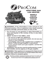
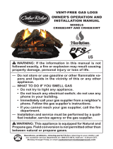
Figure 1 - Product Identication
Grate
Grate Steps
Burner
Pan
Burner
Clamp
Burner
Manifold
Burner Inlet
Fitting

www.usaprocom.com
200035-01B6
AIR FOR COMBUSTION AND VENTILATION
WARNING: If the area in which
the heater may be operated does
not meet the required volume for
indoor combustion air, combus-
tion and ventilation air shall be
provided by one of the methods
described in the National Fuel
Gas Code, ANSI Z223.1/NFPA
54, the International Fuel Gas
Code, or applicable local codes.
Today's homes are built more energy efcient
than ever. New materials, increased insula-
tion, and new construction methods help
reduce heat loss in homes. Home owners
weather strip and caulk around windows and
doors to keep the cold air out and the warm air
in. During heating months, home owners want
their homes as airtight as possible.
While it is good to make your home energy
efcient, your home needs to breathe. Fresh
air must enter your home. All fuel-burning ap-
pliances need fresh air for proper combustion
and ventilation.
Exhaust fans, replaces, clothes dryers, and
fuel burning appliances draw air from the
house to operate. You must provide adequate
fresh air for these appliances. This will en-
sure proper venting of vented fuel-burning
appliances.
WARNING: Before installing
in a solid fuel burning replace,
the chimney ue and rebox
must be cleaned of soot, creo-
sote, ashes, and loose paint by
a qualified chimney cleaner.
Creosote will ignite if highly
heated. A dirty chimney ue may
create and distribute soot within
the house. Inspect chimney ue
for damage.
NOTICE: Installation, service, and repair
of this appliance must be performed by a
qualied installer, service agency, company
or gas supplier experienced with this type of
gas appliance. Only factory authorized com-
ponents listed in these instructions may be
used in accordance with the manufacturer's
instructions and all codes and requirements
of the authority having jurisdiction. Any
modications to this kit, or use of unauthorized
components, or accessory items, will void the
manufacturer's warranty, and may result in a
hazardous condition.
CAUTION: Do not remove
the metal data plates attached to
the burner pan. The data plates
contain important warranty in-
formation.
INSTALLATION
CHECK GAS TYPE
Use only natural gas. If your gas supply is not natural gas, you must install On/Off Safety Pilot
Valve Kit (see Accessories, page 13).
If the replace does not have a gas supply shutoff valve, one must be installed.
The replace chimney ue and vent must be
drafting properly. To check the vent for proper
drafting, light a tightly rolled newspaper on
one end and place it at the inside front edge of
the replace. Observe the smoke and be sure
the vent is properly drawing it up the chimney.
If the smoke spills out into the room, extin-
guish the ame and remove any obstruction
until proper venting is achieved. The chimney
ue must remain open a minimum of 3" at
all times during the operation of this log set.
VENTING SPECIFICATIONS FOR INSTALLATION

www.usaprocom.com
7200035-01B
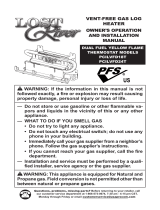
INSTALLING DAMPER CLAMP
Secure the damper stop clamp provided to
the leading edge of the damper as shown in
Figure 2. If for any reason this clamp doesn't
work on your replace, another suitable clamp
or permanent stop must be installed, or the
damper blade must be cut or removed.
INSTALLATION
Figure 2 - Attaching Damper Clamp
Masonry Fireplace
Manufactured
Fireplace
Damper
Damper
Damper
Damper
Clamp
HEARTH KIT ASSEMBLY
Note: The following instructions apply to
dual ame "U" style burners. Be sure all pipe
threaded connections are tight, and have
thread compound to prevent leaks.
1. Determine which side the gas line will be
coming into the replce.
Gas line is on the right side. This unit
is manufactured with the gas inlet on the
right side of the burner pan. See Installa-
tion and Gas Connection, page 8.
Gas line is on the left side. If your gas
line will be coming into the replace from
the left side, continue with step 2.
2. Using a screwdriver, remove cover plate
on left side of burner pan (see Figure 3).
3. Unscrew burner inlet tting from burner
manifold (see Figure 3).
4. Place burner manifold in pan with thread-
ed opening facing opening on left side.
5. Using thread sealant (resistant to the ac-
tion of natural gas) on larger end of tting,
screw the burner inlet tting through hole
and into burner manifold. Tighten using a
wrench.
6. Using burner clamp, screw, and nut pro-
vided, assemble clamp to pan. This will
hold the burner manifold in place.
7. Using screws removed in step 2, install
cover plate over opening on right side of
burner pan.
8. If using optional control system kit, follow
instructions included with kit for installa-
tion and operation.
Burner Pan
Assembly (Facing
Front of Fireplace)
Figure 3 - Installing Burner
Nut
Washer
Burner
Manifold
Burner
Clamp
Cover
Plate
Burner Inlet
Fitting
Screw

www.usaprocom.com
200035-01B8
INSTALLATION
Installation and Gas Connection
1. Place the burner pan assembly in the
center of the replace oor. Make sure
the front of pan faces forward.
2. Thread the gas supply tting to the re-
place gas supply pipe. Use thread sealant.
3. Install adapter tting onto the burner inlet
tting using thread sealant on male threads
of burner inlet tting (see Figure 4).
4. Install the gas connector tube to the gas
supply tting. Carefully shape tube to at-
tach to adapter tting.
Figure 4 - Connecting Gas to Appliance
Burner Pan Assembly
(Facing Front of
Fireplace)
Adapter Fitting
Gas
Connector
Tube
CONNECTION TO GAS SUPPLY
WARNING: A qualied ser-
vice person must connect log
set to gas supply. Follow all
local codes.
Installation Items Needed
Before installing log set, make sure you have
the items listed below.
• piping (check local codes)
• sealant (resistant to natural gas)
• equipment shutoff valve
• test gauge connection
• adjustable (crescent) wrench or pliers
• sediment trap
• tee joint
• pipe wrench
CAUTION: Only use a new,
black iron or steel pipe. Inter-
nally-tinned copper tubing may
be used in certain areas. Check
your local codes. Use pipe of
1/2" diameter or greater to allow
proper gas volume to log set. If
pipe is too small, loss of pres-
sure will occur.
Installation must include an equipment shut-
off valve, union, and plugged 1/8" NPT tap.
Locate NPT tap within reach for test gauge
hook up. NPT tap must be upstream from log
set (see Figure 5).
IMPORTANT: Install equipment shutoff valve
in an accessible location. The equipment
shutoff valve is for turning on or shutting off
the gas to the appliance.
Apply pipe joint sealant lightly to male threads.
This will prevent excess sealant from going
into pipe. Excess sealant in pipe could result
in a clogged burner injector.
Install sediment trap in supply line as shown
in Figure 5. Locate sediment trap where it is
within reach for cleaning. Locate sediment
trap where trapped matter is not likely to
freeze. A sediment trap traps moisture and
contaminants. This keeps them from going
into log set controls. If sediment trap is not
installed or is installed incorrectly, log set may
not run properly.
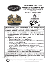
Figure 5 - Gas Connection
Approved Flexible Gas Hose
(if allowed by local codes)
CSA Design - Certied
Equipment Shutoff Valve
with 1/8" NPT Tap*
3" Minimum
From Gas Meter
(5" W. C.**
to 10.5" W. C.)
pressure
Sediment Trap
Cap Pipe Tee
Nipple Joint
* Purchase the optional
CSA design-certified
equipment shutoff valve
from dealer. See Acces-
sories page 13.
** Minimum inlet pres-
sure for purpose of input
adjustment.

www.usaprocom.com
9200035-01B
INSTALLATION
CHECKING GAS CONNECTIONS
WARNING: Test all gas piping
and connections for leaks after
installing or servicing. Correct
all leaks immediately.
WARNING: Never use an
open ame to check for a leak.
Apply a noncorrosive leak detec-
tion uid to all joints. Bubbles
forming show a leak. Correct all
leaks immediately.
PRESSURE TESTING GAS SUPPLY PIPING SYSTEM
Test Pressures In Excess Of 1/2 PSIG ( 3.5kPa )
1. Disconnect heater with its appliance main
gas valve (control valve) and equipment
shutoff valve from gas supply piping sys-
tem. Pressures in excess of 1/2 PSIG will
damage heater regulator.
2. Cap off open end of gas pipe where equip-
ment shutoff valve was connected.
3. Pressurize supply piping system by either
using compressed air or opening gas sup-
ply tank valve.
4. Check all joints of gas supply piping sys-
tem. Apply a noncorrosive leak detection
uid to gas joints. Bubbles forming show
a leak.
5. Correct all leaks immediately.
6. Reconnect log set and equipment shutoff
valve to gas supply. Check reconnected
ttings for leaks.
Test Pressures Equal To or Less Than 1/2 PSIG (3.5 kPa)
1. Close equipment shutoff valve (see Fig-
ure 6).
2. Pressure supply piping system by either
using compressed air or opening gas
supply tank valve.
3 Check all joints from gas meter to equip-
ment shutoff valve (see Figure 7). Apply
a noncorrosive leak detection uid to gas
joints. If bubbles form, there may be a
leak.
4. Correct all leaks immediately.
Figure 6 - Equipment Shutoff Valve
Open
Closed
Equipment
Shutoff Valve
Figure 7 - Checking Gas Joints
Equipment Shutoff Valve
Gas Meter

www.usaprocom.com
200035-01B10
INSTALLATION
TESTING BURNER FOR LEAKS
WARNING: Never check for
gas leaks with open ame.
1. Generously apply a noncorrosive leak
detection uid to all connections.
2. Light the burner with the shutoff valve, no
more than half open, and holding a match
slightly in front of the pan (see Lighting
Instructions, page 12).
3. Inspect all connections for bubbles,
raw gas odor, or ame from any area
other than the burner (leaks). If leaks are
detected, shut off the gas valve immedi-
ately. Tighten, or reassemble the loose
connection(s) using pipe joint compound
until burner system is leak free.
4. When the burner is tested and leak free,
observe the individual tongues of ame
on the burner.
Note: Let the burner manifold cool rst
before removing to unclog port blockages.
The burner design includes more ports
on the outside of the bar. Make sure that
all ports are clear and producing ame
evenly across the burner. If any ports
appear blocked, clear them by removing
the burner manifold and reaming the ports
with a modied paper clip or other suit
able tool.
5. When nished testing, turn the gas shutoff
valve OFF to extinguish all ames.
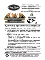
INSTALLING LOGS
WARNING: Failure to posi-
tion the parts in accordance
with these diagrams or failure
to use only parts specically
approved with this heater may
result in property damage or
personal injury.
Vermiculite and Glowing Ember
Log #1
Log #2
Log #3
Log #4
3. Place log #3 on log #1 and log #2.
4. Place log #4 on log #1 and log #2.
1. Place vermiculite into burner pan. Pull
glowing ember loosely, and sprinkle
uniformly on the surface of vermiculite
as shown on page 11. Insert log #1 into
slots in rear log bracket on grate base.
2. Insert log #2 into slots in middle grate
bracket.
It is very important to install the logs exactly
as instructed. Do not modify logs. Use only
logs supplied with heater.
Each log is marked with a number. This
number will help you to identify the logs when
installing.
After installing logs, add decorative cinders
around the grate base, do not place any
decorative cinders on logs or burner.
MODEL CRHEAV18RP

www.usaprocom.com
11200035-01B
INSTALLATION
Glowing Embers
Vermiculite
Vermiculite and Glowing Ember
Log #1
Log #3
Log #5
Log #6-3
Log #6-2
Log #6-1
Log #2
Log #4
Log #5
Log #7-1
Log #7-2
Log #7-3
Log #65. Place log #5 on log #4 and log #2.
6. Place log #6 on log #1 and log #2. And
place log #7-1, #7-2, #7-3 in front.
MODELS CRHWV24RP AND CRHWV30RP
5. Place log #5 on log #4 and log #2.
6. Place log #6-1, #6-2, #6-3 in front.
3. Place log #4 on log #2 and grate.
4. Place log #3 on log #1 and log #4.
1. Place vermiculite into burner pan. Pull
glowing ember loosely, and sprinkle uni-
formly on the surface of vermiculite as
shown below. Insert log #1 into slots in
rear log bracket on grate base.
2. Insert log #2 into slots in right log bracket
on grate base.

www.usaprocom.com
200035-01B12
OPERATION
FOR YOUR SAFETY READ BEFORE LIGHTING
WARNING: If you do not fol-
low these instructions exactly, a
re or explosion may result caus-
ing property damage, personal
injury or loss of life.
A. This appliance has a pilot which must
be lighted by hand. When lighting the
pilot, follow these instructions exactly.
B. BEFORE LIGHTING smell all around the
appliance area for gas. Be sure to smell
next to the oor because some gas is
heavier than air and will settle on the oor.
WHAT TO DO IF YOU SMELL GAS
• Do not try to light any appliance.
• Do not touch any electric switch; do
not use any phone in your building.
• Immediately call your gas supplier
from a neighbor’s phone. Follow the
gas supplier’s instructions.
• If you cannot reach your gas supplier,
call the re department.
C. Use only your hand to push in or turn
the gas control knob. Never use tools.
If the knob will not push in or turn by
hand, don’t try to repair it, call a qualied
service technician. Force or attempted
repair may result in a re or explosion.
D. Do not use this appliance if any part
has been under water. Immediately call
a qualied service technician to inspect
the appliance and to replace any part of
the control system and any gas control
which has been under water.
LIGHTING INSTRUCTIONS
1. STOP! Read the safety information above.
2. Turn the gas shutoff valve to OFF.
3. Wait ve (5) minutes to clear out any
gas. If you still smell gas, STOP! Follow
the safety information above. If you don't
smell gas, go on to the next step.
4. Light a match and lay it on top of the pan
material about 2" from the end of the sup-
ply side of the pan.
5. Slowly turn the gas shutoff valve ON until
the burner ignites. If the burner doesn't
ignite within 10 seconds with the match
burning, turn the shutoff valve OFF and
repeat steps 1 through 4 again.
GAS SHUTOFF VALVE OPERATION
Flame Adjustment
Adjust the ame ON/OFF by turning the gas
shutoff valve counterclockwise to open
or clockwise to close, as necessary.
Shutting Off Appliance
Turn gas shutoff valve clockwise to the
OFF position.
CURING LOGS
During the 2-3 hour appliance curing period,
you may detect an odor from the appliance
as the various paints and compounds used in
the manufacturing of this log set cure. This is
a normal and temporary situation that is not
cause for alarm. However, you may want to
provide extra ventilation to the room during
this time.
To ensure proper curing of the logs:
• Ignite a 2" ame and maintain it for 1 hour.
• Burn the logs in consecutive 1 hour periods
raising the ame an additional 2" to full
ame height for a total of three hours.

www.usaprocom.com
13200035-01B
CARE AND MAINTENANCE
• Keep the area around the log set clean and clear of debris.
• Occasionally, you may use a soft bristle brush to clean logs.
• Once every year a qualied agency or certied chimney sweep should examine and clean
the venting system of the replace.
ACCESSORIES
Purchase these replace accessories from your local dealer. If they can not supply these
accessories, contact customer service department for information.
EQUIPMENT SHUTOFF VALVE
For all models. Equipment shutoff valve with
1/8" NPT tap. Fits 1/2" NPT pipe.
NVDWA1 - ON/OFF SAFETY PILOT
VALVE KIT
For all models. Required for propane/LP
installation.

www.usaprocom.com
200035-01B14
TROUBLESHOOTING
WARNING: If you smell gas:
• Shut off gas supply.
• Do not try to light any appliance.
• Do not touch any electrical switch; do not use any phone in your
building.
• Immediately call your gas supplier from a neighbor’s phone. Fol-
low the gas supplier’s instructions.
• If you cannot reach your gas supplier, call the re department.
WARNING: Only a qualied service technician should service and
repair heater. Make sure that power is turned off before proceeding.
Turn off and let cool before servicing.
CAUTION: Never use a wire, needle, or similar object to clean
ODS/pilot. This can damage ODS/ pilot unit.
IMPORTANT: Operating heater where impurities in air exist may create odors. Cleaning sup-
plies, paint, paint remover, cigarette smoke, cements and glues, new carpet or textiles, etc.,
create fumes. These fumes may mix with combustion air and create odors.
Note: All troubleshooting items are listed in order of operation.
Problem Possible Cause Corrective Action
Log set is smoking/ soot-
ing excessively
Note: It is natural and
unavoidable for vented
gas log sets to produce
moderate levels of car-
bon (soot) where ames
contact the logs.
1. Poor fuel quality.
2. Fireplace venting system not
drafting properly.
3. Excessive flame impinge-
ment or blockage.
4. Improper fuel/air mixture.
5. Excessive gas supply/ pres-
sure.
1. Contact local natural gas
company.
2. Adjust damper wide open
and/or have fireplace and
venting professionally
cleaned and checked.
3. Separate the logs to allow
more ame passage.
4. Remove any foreign items
from the ame pattern.
5. Preheat flue in very cold
weather.
Burner is excessively
noisy. Note: The move-
ment and combustion of
gas will create low, un-
avoidable levels of noise.
1. Passage of air/gas across
irregular surfaces.
1. Relieve any tight bends or
kinks in gas supply line.
Burner ame is too low or
too high.
1. Incorrect gas supply or pres-
sure.
2 Blocked burner orifice or
burner manifold ports.
3. Improper burner orice size.
1. Check for proper gas supply
pressure.
2. Free burner orice and mani-
fold ports of any burrs, paint,
or other blockage.
3. Verify proper burner orice
sizing (see page 3).

www.usaprocom.com
15200035-01B
Problem Possible Cause Corrective Action
Log set produces a click-
ing/ticking noise just after
burner is lit or shut off.
1. Metal expanding while heat-
ing or contracting while cool-
ing.
1. This is common with most
log sets. If noise is exces-
sive, contact qualied ser-
vice person.
Log set produces un-
wanted odors.
1. Log Set burning vapors
from paint, hair spray, glues,
cleaners, chemicals, new
carpet, etc. (See IMPOR-
TANT statement page 14).
2. Gas leak. See Warning
statement page 14.
1. Open ue to maximum. Stop
using odor causing products
while log set is running.
2. Locate and correct all leaks
(see Checking Gas Connec-
tions, page 9).
Gas odor even when
control knob is in OFF
position.
1. Gas leak. See Warning
statement page 14.
2. Control valve defective
1. Locate and correct all leaks
(see Checking Gas Connec-
tions, page 9).
2. Replace control valve.
Gas odor during com-
bustion.
1. Gas leak. See Warning
statement at top of page 14.
1. Locate and correct all leaks
(see Checking Gas Connec-
tions, page 9).
TROUBLESHOOTING
REPLACEMENT PARTS
Contact authorized dealers of this product.
If they can’t supply original replacement
parts, call Customer Service toll free at
1-866-573-0674 for referral information.
When calling Customer Service or your
dealer, have ready:
• Your name
• Your address
• Model and serial number of your heater
• How heater was malfunctioning
• Type of gas used (Propane/LP or Natural
gas/NG)
• Purchase date
Usually, we will ask you to return the defective
part to the factory
Note: Use only original replacement parts. This will protect your warranty coverage for parts
replaced under warranty.
PARTS UNDER WARRANTY
PARTS NOT UNDER WARRANTY
Contact authorized dealers of this product.
If they can’t supply original replacement
part(s) call Customer Service toll free at
1-866-573-0674 for referral information.
When calling Customer Service have ready:
• Model number of your heater
• The replacement part number

www.usaprocom.com
200035-01B16
PARTS
MODELS CRHEAV18RP CRHWV24RP AND CRHWV30RP
4
4
1
2
3

www.usaprocom.com
17200035-01B
PARTS
MODELS CRHEAV18RP CRHWV24RP AND CRHWV30RP
This list contains replaceable parts used in your heater. When ordering parts, follow the
instructions listed under Replacement Parts on page 15 of this manual.
ITEM CRHEAV18RP DESCRIPTION QTY
1 **BL050-01 3/8" Female x 5/8" Flare Adapter
1
2 **WAL06-01 Injector Mounting 1
3 **WAL07-01N Injector 1
4 **WAB18-01 Grate Step 2
PARTS AVAILABLE - NOT SHOWN
WAL11-01 Vermiculite 1
GLEMVERM25 Glowing Embers 1
SSEAV18B Log Assembly 1
SSEAV18-1 Log 1 1
SSEAV18-2 Log 2 1
SSEAV18-3 Log 3 1
SSEAV18-4 Log 4 1
SSEAV18-5 Log 5 1
SSEAV18-6 Log 6 1
BAVIN-1 Log 7-1 1
BAVIN-2 Log 7-2 1
BAVIN-3 Log 7-3 1
WAN300B Hardware Package 1
WAB03 Damper Clamp 1
ITEM CRHWV24RP CRHWV30RP DESCRIPTION QTY
1 **BL050-01 **BL050-01 3/8" Female x 5/8" Flare Adapter
1
2 **WAL06-01 **WAL06-01 Injector Mounting 1
3 **WAL07-02N **WAL07-03N Injector 1
4 **WAB18-01 **WAB18-01 Grate Step 2
PARTS AVAILABLE - NOT SHOWN
WAL11-01 WAL11-01 Vermiculite 1
GLEMVERM25 GLEMVERM25 Glowing Embers 1
SSWV24B SSWV30B Log Assembly 1
SSWV24-1 SSWV30-1 Log 1 1
SSWV24-2 SSWV30-2 Log 2 1
SSWV24-3 SSWV30-3 Log 3 1
SSWV24-4 SSWV30-4 Log 4 1
SSWV24-5 SSWV30-5 Log 5 1
BAVIN-1 BAVIN-1 Log 6-1 1
BAVIN-2 BAVIN-2 Log 6-2 1
BAVIN-3 BAVIN-3 Log 6-3 1
WAN300B WAN300B Hardware Package 1
WAB03 WAB03 Damper Clamp 1
** Not a eld replaceable part.

www.usaprocom.com
200035-01B18
NOTES
________________________________________________________________________
________________________________________________________________________
________________________________________________________________________
________________________________________________________________________
________________________________________________________________________
________________________________________________________________________
________________________________________________________________________
________________________________________________________________________
________________________________________________________________________
________________________________________________________________________
________________________________________________________________________
________________________________________________________________________
________________________________________________________________________
________________________________________________________________________
________________________________________________________________________
________________________________________________________________________
________________________________________________________________________
________________________________________________________________________
________________________________________________________________________
________________________________________________________________________
________________________________________________________________________
________________________________________________________________________
________________________________________________________________________
________________________________________________________________________
________________________________________________________________________
________________________________________________________________________
________________________________________________________________________
________________________________________________________________________
________________________________________________________________________
________________________________________________________________________
________________________________________________________________________
________________________________________________________________________
________________________________________________________________________

www.usaprocom.com
19200035-01B
NOTES
________________________________________________________________________
________________________________________________________________________
________________________________________________________________________
________________________________________________________________________
________________________________________________________________________
________________________________________________________________________
________________________________________________________________________
________________________________________________________________________
________________________________________________________________________
________________________________________________________________________
________________________________________________________________________
________________________________________________________________________
________________________________________________________________________
________________________________________________________________________
________________________________________________________________________
________________________________________________________________________
________________________________________________________________________
________________________________________________________________________
________________________________________________________________________
________________________________________________________________________
________________________________________________________________________
________________________________________________________________________
________________________________________________________________________
________________________________________________________________________
________________________________________________________________________
________________________________________________________________________
________________________________________________________________________
________________________________________________________________________
________________________________________________________________________
________________________________________________________________________
________________________________________________________________________
________________________________________________________________________
________________________________________________________________________

200035-01
Rev. B
06/14
WARRANTY
KEEP THIS WARRANTY
Model _______________________________
Serial No. ____________________________
Date Purchased _______________________
Keep receipt for warranty verication.
ProCom Heating, Inc.
Bowling Green, KY 42101
www.usaprocom.com
1-866-573-0674
REGISTER YOUR PRODUCT AT WWW.USAPROCOM.COM
IMPORTANT: We urge you to register your product within 10 days of date of installation, complete
with entire serial number which can be found on the rating plate. Please ll out the warranty infor-
mation above for your personal records. Retain this manual for future reference.
Always specify model and serial numbers when communicating with customer service.
We reserve the right to amend these specications at any time without notice. The only warranty applicable
is our standard written warranty. We make no other warranty, expressed or implied.
LIMITED WARRANTY
ProCom Heating, Inc. warrants this product to be free from defects in materials and components for
TWO (2) years from the date of rst purchase, provided that the product has been properly installed by a
qualied installer in accordance with all local codes and instructions furnished with the unit, operated and
maintained in accordance with all applicable instructions. To make a claim under this warranty, the Bill of
Sale or canceled check must be presented.
RESPONSIBILITY OF OWNER
This warranty is extended only to the original retail purchaser. This warranty covers the cost of part(s)
required to restore this heater to proper operating condition. Warranty part(s) MUST be obtained through
ProCom Heating, Inc. who will provide original factory replacement parts. Failure to use original factory
replacement parts voids this warranty.
IMPORTANT: The heater MUST be installed by a qualied installer in accordance with all local codes
and instructions furnished with the unit or the warranty is voided.
WHAT IS NOT COVERED
This warranty does not apply to parts that are not in original condition because of normal wear and tear or
parts that fail or become damaged as a result of misuse, accidents, lack of proper maintenance or defects
caused by improper installation. Travel, diagnostic cost, labor, transportation and any and all such other
costs related to repairing a defective heater will be the responsibility of the owner.
TO THE FULL EXTENT ALLOWED BY THE LAW OF THE JURISDICTION THAT GOVERNS THE SALE
OF THE PRODUCT, THIS EXPRESS WARRANTY EXCLUDES ANY AND ALL OTHER EXPRESSED
WARRANTIES AND LIMITS THE DURATION OF ANY AND ALL IMPLIED WARRANTIES. INCLUDING
WARRANTIES OF MERCHANTABILITY AND FITNESS FOR A PARTICULAR PURPOSE TO TWO (2)
YEARS ON ALL COMPONENTS FROM THE DATE OF FIRST PURCHASE. PROCOM HEATING, INC.'S
LIABILITY IS HEREBY LIMITED TO THE PURCHASE PRICE OF THE PRODUCT AND PROCOM HEAT-
ING, INC. SHALL NOT BE LIABLE FOR ANY OTHER DAMAGES WHATSOEVER INCLUDING INDIRECT,
INCIDENTAL OR CONSEQUENTIAL DAMAGES.
Some states do not allow a limitation on how long an implied warranty lasts or an exclusion or limitation of
accidental or consequential damages, the above limitation on implied warranties, or exclusion or limitation
on damages may not apply to you.
This warranty gives you specic legal right, and you may also have other rights that vary from state to state.
/