Superior Fireplaces VRE3200 Operating instructions
- Category
- Stoves
- Type
- Operating instructions
This manual is also suitable for

42" x 24" and 36" x 24"
Universal Vent-Free Fireboxes
P/N 900853-00 REV. D 12/2020
MODELS
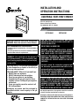
UNIVERSAL VENT-FREE FIREBOX
INSTALLATION AND
OPERATION INSTRUCTIONS
VRT2536WS VRT2542WS
Due to high temperatures, the appliance should be located out
of traffic and away from furniture or draperies.
Do not place clothing or other materials on or near this appliance.
IMPORTANT: READ AND UNDERSTAND THESE INSTRUCTIONS
COMPLETELY BEFORE INSTALLING YOUR VENT-FREE ROOM
HEATERS.
FOR USE ONLY WITH A LISTED GAS-FIRED
UNVENTED DECORATIVE ROOM HEATER NOT TO
EXCEED 40,000 BTU/H.
DO NOT BUILD A WOOD FIRE.
WARNING: IMPROPER INSTALLATION, ADJUST-
MENT, ALTERATION, SERVICE OR MAINTENANCE
CAN CAUSE INJURY OR PROPERTY DAMAGE.
REFER TO THIS MANUAL. FOR ASSISTANCE OR
ADDITIONAL INFORMATION CONSULT A QUALI-
FIED INSTALLER, SERVICE AGENCY OR THE GAS
SUPPLIER.
Carefully review the instructions supplied with
the decorative type unvented room heater for the
minimum fireplace size requirement.
DO NOT INSTALL AN APPLIANCE IN THIS FIREBOX
UNLESS THIS FIREBOX MEETS THE MINIMUM
DIMENSIONS REQUIRED FOR THE INSTALLATIONS.
THIS IS A VENT-FREE GAS-FIRED HEATER ENCLO-
SURE. IT USES AIR (OXYGEN) FROM THE ROOM
IN WHICH IT IS INSTALLED. PROVISIONS FOR
ADEQUATE COMBUSTION AND VENTILATION AIR
MUST BE PROVIDED. REFER TO COMBUSTION
AND VENTILATION AIR SECTION, PAGES 3 AND 4.
INSTALLER: Leave this manual with the appliance.
CONSUMER: Retain this manual for future reference.
FOR YOUR SAFETY: Do not store or use gasoline
or other flammables or liquids in the vicinity of
this or any other appliance.
FOR YOUR SAFETY: What to do if you smell gas:
• DO NOT light any appliance.
• DO NOT touch any electrical switches.
• Do not use any phone in your building.
• Immediately call your gas supplier from a
neighbor’s phone. Follow your gas suppliers
instructions.
• If your gas supplier cannot be reached, call
the fire department.
Installation and service must be performed by
a qualified installer, service agency or the gas
supplier.
WARNING: If the information in this manual is
not followed exactly, a fire or explosion may
result causing property damage, personal injury
or loss of life.
In the Commonwealth of Massachusetts:
• Installation must be performed by a licensed plumber or
gas fitter;
• See Table of Contents for location of additional Common-
wealth of Massachusetts requirements.
CUS
Report No. F14-168
P900853-00

2
IMPORTANT SAFETY
INFORMATION
INSTALLER: PLEASE LEAVE THESE INSTRUC-
TIONS WITH THE OWNER.
OWNER: PLEASE RETAIN THESE INSTRUC-
TIONS FOR FUTURE REFERENCE.
WARNING
If the information in this
manual is not followed
exactly, a fire or explosion
may result causing prop-
erty damage, personal
injury or loss of life.
IMPORTANT
Before starting your firebox instal-
lation, read these installation
instructions carefully to be sure you
understand them completely and
in entirety. Failure to follow these
instructions could cause a heater
malfunction resulting in serious
injury and/or property damage.
IMPORTANT
The fireplace screens on the appli-
ance must be closed prior to operat-
ing the fireplace.
WARNING
These built-in vent-free fireboxes
have only been tested and approved
for use with ANSI Z21.11.2 Vent-
free gas logs.
WARNING
Any change to this Vent-Free room
heater can be dangerous. Improper
installation or use of this heater can
cause serious injury or death from
fire, burns, explosion or carbon
monoxide poisoning.
WARNING
Do not attempt to burn solid wood
fuels, other gas log sets or any
other combustible materials in
this vent-free firebox.
WARNING
Carbon Monoxide Poisoning: Early
signs of carbon monoxide poisoning
are similar to the flu with head-
aches, dizziness and/or nausea. If
you have these signs, obtain fresh
air immediately. Have the Vent-Free
Gas Heater serviced as it may not
be operating correctly.
WARNINGS
• Due to high temperatures, the
firebox should be located out of
traffic and away from furniture
and draperies.
• Do not place clothing or other
flammable material on or near
the heater.
• Any safety screen or guard re-
moved for servicing the firebox
must be replaced and/or closed
prior to operating the heater.
• Installation and repair should
be done by a qualified service
person. The heater should be
inspected before use and at
least annually by a professional
service person. More frequent
cleaning may be required due
to excessive lint from carpet-
ing, bedding material, etc. It is
important that control compart-
ments, burners and circulating
air passageways of the heater
be kept clean.
• Allow the heater to cool before
servicing. Always shut off any
electricity or gas to the heater
while performing service work.
• Do not install the firebox in a
sleeping room or bathroom.
• The appliance and its individual
shut-off valve must be discon-
nected from the gas supply piping
system while performing any
tests of the gas supply piping
system at test pressures equal
to or less than 1/2 psig.
WARNING
• The heater must be isolated from
the gas supply piping system by
closing its individual manual
shut-off valve during any pres-
sure testing of the gas supply
piping system at test pressures
equal to or less than 1/2 psig.
• Keep heater area clear and free
from combustible materials,
gasoline and other flammable
vapors and liquids.
• Do not use this heater if any
part has been under water. Im-
mediately call a qualified service
technician to inspect the heater
and to replace any part of the con-
trol system and any gas control
which has been under water.
• Ensure that the heater is clean
when operating. Excessive dust
accumulation on the burner and
logs will increase the amount of
carbon monoxide formation and
could lead to carbon monoxide
poisoning and death.
WARNING
Do not install in the vicinity where
gasoline or other flammable liq-
uids may be stored. The Vent-Free
firebox must be kept clear and free
from these combustible materials.
WARNING
Maintain minimum clearances.
WARNING
Do not allow fans to blow directly
into the fireplace. Avoid any drafts
that alter burner flame patterns.

3
Misc. Codes / Standards -
The Installation must conform to local codes
or, in the absence of local codes, with the
National Fuel Gas Code, ANSI Z223.1/NFPA
54 - latest edition.
The appliance, when installed, must be electri-
cally grounded in accordance with local codes or,
in the absence of local codes, with the National
Electrical Code, ANSI/NFPA 70 - latest edition.
Check the packaging list to be sure that you
have all the necessary parts in usable condition.
Also check for concealed damage.
Tools and Building Supplies
Normally Required
Tools Should Include:
• Phillips screwdriver
• Hammer
• Saw and/or sabersaw
• Level
• Measuring tape
• Electric drill and bits
• Pliers
• Square
• Piping complying with local codes
• Pipe wrench
• Tee joint
• Pipe compound
Building Supplies Should Include:
• Framing materials
• Wall finishing materials
• Caulking materials
(noncombustible)
• Fireplace surround materials
(noncombustible)
• Insulation
(for packing around gas-line penetration holes)
Codes
Adhere to all local codes or in their absence
the latest edition of The National Fuel Gas Code
ANSI Z223.1 or NFPA 54 - latest edition which
can be obtained from The American National
Standards Institute, Inc. (25 West 43rd Street,
4th floor New York, NY 10036) or National Fire
Protection Association, Inc. (1 Batterymarch
Park Quincy, MA 02169-7471).
TABLE OF CONTENTS
Important Safety Information ........... Page 2
Packaging List .................................. Page 3
General Information ......................... Page 3
Burn-in Period .................................. Page 3
Tools/Building Supplies .................... Page 3
Codes ............................................... Page 3
Combustion And Ventilation Air ....... Page 3
Cold Climate Insulation .................... Page 4
Requirements for the
Commonwealth of Massachusetts Page 5
Location Of Firebox .......................... Page 6
Clearances ....................................... Page 6
Assembly Steps ............................... Page 8
Gas Line Installation ......................... Page 8
Firebox Framing ............................... Page 9
Firebox Installation ........................... Page 9
Specifications ................................... Page 10
Framing Specifications ..................... Page 11
Hood Installation .............................. Page 11
Optional Equipment / Blower Kit
Installation .................................. Page 12
Firebox Finishes ............................... Page 15
Accessories/components ................. Page 15
Replacement Parts List .................... Page 17
Warranty .......................................... Page 19
This installation manual will help you obtain
a safe, efficient, dependable installation for
your appliance and vent system.
PLEASE READ AND UNDERSTAND
THESE INSTRUCTIONS BEFORE BEGIN-
NING YOUR INSTALLATION.
Packaging List
Vent-Free Gas Firebox
Hood
Installation and Operation Instructions
GENERAL INFORMATION
These Vent-Free firebox enclosures are designed
to accept all ANSI Z21.11.2 approved Decorative
Type Vent-Free Gas Log Room Heaters. For the
appropriate Vent-Free Gas Log Room Heater
model, refer to Page 16 (see
Vent-Free Gas Log
Sets)
. Refer to the installation instructions pro-
vided with the log sets for detailed instructions.
This installation manual along with the vent-free
gas log installation manual will enable you to
obtain a safe, efficient and dependable instal-
lation of your room heater system.
Do not alter or modify the firebox or its
com ponents under any circumstances. Any
modification or alteration of the firebox system,
including but not limited to the firebox and ac-
cessories, may void the warranty, listings and
approvals of this system and could result in an
unsafe and potentially dangerous installation.
These Built-In Vent-Free Fireboxes have been
tested and approved as Ventless Firebox Enclo-
sures for Gas-Fired Unvented Decorative Room
Heaters to ANSI Z21.91.
Burn-in Period
During the first few times of operation of this
appliance there will be some odor due to the
curing of the paint and burning off of lubricants
used in the manufacturing process. We recom-
mend that you open windows and ventilate the
house during the initial burns. The paint emits
non-toxic odors during this process.
Depending on your use, the burn-in period may
take a few hours or a few days.
KEEP YOUR HOUSE WELL VENTILATED
DURING THE BURN-IN PERIOD. THE ODOR
AND HAZE EMITTED DURING THE BURN-IN
PERIOD CAN BE QUITE NOTICEABLE AND MAY
SET OFF A SMOKE DETECTOR.
If an optional blower is installed, Do not turn it
on during the Burn-In period.
CONGRATULATIONS!
In selecting this Superior
®
Vent-Free Gas Firebox you have chosen the finest and most
dependable fireplace to be found anywhere. A beautiful, prestigious, alternative to a
wood burning fireplace. Welcome to a family of tens of thousands of satisfied Superior
Fireplace Owners.
Please read and carefully follow all of the instructions found in this manual. Please pay
special attention to the safety instructions provided in this manual. The Homeowner's
Care and Operation Instructions included here will assure that you have many years of
dependable and enjoyable service from your Superior product.

NOTE: DIAGRAMS & ILLUSTRATION ARE NOT TO SCALE.
4
WARNING
If the area in which the heater may be
operated does not meet the required
volume for indoor combustion air,
combustion and ventilation air shall
be provided by one of the methods
described in the National Fuel gas
Code, ANSI Z223.1/NFPA 54, the Inter-
national Fuel gas Code, or applicable
local codes.
Today’s homes are built more energy efficient
than ever. New materials, increased insulation
and new construction methods help reduce
heat loss in homes. Homeowners apply weather
strip and caulk around windows and doors to
keep the cold air out and the warm air in. During
heating months, homeowners want their homes
as airtight as possible.
While it is good to make your home energy
efficient, your home needs to breathe. Fresh
air must enter your home. All fuel-burning ap-
pliances need fresh air for proper combustion
and ventilation.
Exhaust fans, some fireplaces, clothes dryers
and some fuel-burning appliances draw air
from the house to operate. You must provide
adequate fresh air for these appliances. This will
ensure proper venting of vented fuel-burning
appliances.
PROVIDING ADEQUATE VENTILATION
The following are excerpts from National Fuel
Gas Code, ANSI Z223.1/NFPA 54, Air for Com-
bustion and Ventilation.
All spaces in homes fall into one of the three
following ventilation classifications:
1. Unusually Tight Construction
2. Unconfined Space
3. Confined Space
The information on Pages 8 through 10 will help
you classify your space and provide adequate
ventilation.
Unusually Tight Construction
The air that leaks around doors and windows
may provide enough fresh air for combustion
and ventilation. However, in buildings of un-
usually tight construction, you must provide
additional fresh air.
Unusually tight construction is defined as
construction where:
a. walls and ceilings exposed to the outside
atmosphere have a continuous water
vapor retarder with a rating of one perm
(6 x 10
-11
kg per pa-sec-m
2
) or less with
openings gasketed or sealed and
b. weather stripping has been added on
openable windows and doors and
WARNING
Heaters installed in these appli-
ances shall not be installed in a
room or space unless the required
volume of indoor combustion air is
provided by the method described
in the National Fuel Gas Code, ANSI
Z223.1/NFPA 54, the International
Fuel Gas Code, or applicable local
codes. Read the following instruc-
tions to ensure proper fresh air for
this and other fuel-burning appli-
ances in your home.
c. caulking or sealants are applied to areas
such as joints around window and door
frames, between sole plates and floors,
between wall-ceiling joints, between
wall panels, at penetrations for plumb-
ing, electrical and gas lines and at other
openings.
If your home meets all of the three criteria
above, you must provide additional fresh air.
See Ventilation Air From Outdoors, in the In
-
stallation and Operation manual for the heater.
If your home does not meet all of the three
criteria above, proceed to Determining
Fresh-Air Flow For Firebox Location.
Confined and Unconfined Space
The National Fuel Gas Code, ANSI Z223.1/
NFPA54 allows two methods for determining
whether the space in which the heater is being
installed is confined or unconfined space. The
standard method defines a confined space as
a space whose volume is less than 50 cubic
feet per 1,000 Btu per hour (4.8 m
3
per kw)
of the aggregate input rating of all appliances
installed in that space and an unconfined
space as a space whose volume is not less
than 50 cubic feet per 1,000 Btu per hour (4.8
m
3
per kw) of the aggregate input rating of all
appliances installed in that space. Rooms com-
municating directly with the space in which the
appliances are installed*, through openings
not furnished with doors, are considered a
part of the unconfined space.
Where the air infiltration rate of a structure
is known, the Known Air Infiltration Rate
Method may be used. Follow The National Fuel
Gas Code, ANSI Z223.1/NFPA 54 to use this
method to determine if the space is confined
or unconfined.
* Adjoining rooms are communicating only if
there are doorless passageways or ventilation
grills between them.
DETERMINING FRESH-AIR FLOW FOR
Heater LOCATION
Determining if You Have a Confined or
Unconfined Space Using the Standard
Method
Use this work sheet to determine if you have
a confined or unconfined space.
Space: Includes the room in which you will
install heater plus any adjoining rooms with
doorless passageways or ventilation grills
between the rooms.
1. Determine the volume of the space (length
x width x height).
Length x Width x Height =__________cu.
ft. (volume of space)
Example
: Space size 22 ft. (length) x 18
ft. (width) x 8 ft. (ceiling height) = 3,168
cu. ft. (volume of space)
If additional ventilation to adjoining room
is supplied with grills or openings, add the
volume of these rooms to the total volume
of the space.
2. Multiply the space volume by 20 to determine
the maximum BTU/Hr the space can support.
________ (volume of space) x 20 = (Maxi-
mum BTU/Hr the space can support)
Example
: 3,168 cu. ft. (volume of space) x
20 = 63,360 (maximum BTU/Hr space can
support)
3. Add the BTU/Hr of all fuel burning appli
-
ances in the space.
Vent-free fireplace ________ BTU/Hr
Gas water heater* ________ BTU/Hr
Gas furnace ________ BTU/Hr
Vented gas heater ________ BTU/Hr
Gas fireplace logs ________ BTU/Hr
Other gas appliances* + _______ BTU/Hr
Total = ________ BTU/Hr
* Do not include direct-vent gas appli
-
ances. Direct-vent draws combustion
air from the outdoors and vents to the
outdoors.
Example:
Gas water heater
40,000
BTU/Hr
Vent-free fireplace +
39,000
BTU/Hr
Total =
79,000
BTU/Hr
4. Compare the maximum BTU/Hr the space
can support with the actual amount of BTU/
Hr used.
_______ BTU/Hr (maximum the space can
support)
_______ BTU/Hr (actual amount of BTU/Hr
used)
Example
: 63,360 BTU/Hr (maximum the
space can support)
79,000 BTU/Hr (actual amount
of BTU/Hr used)
The space in the example is a confined space
because the actual BTU/Hr used is more than
the maximum BTU/Hr the space can support.
You must provide additional fresh air. Your
options are as follows:
A. Rework worksheet, adding the space
of an adjoining room. If the extra space
provides an unconfined space, remove
door to adjoining room or add ventilation
grills between rooms. See Ventilation Air
From Inside Building
,
in the Installation and
Operation manual for the heater
.
B. Vent room directly to the outdoors. See
Ventilation Air From Outdoors,
in the Instal-
lation and Operation manual for the heater
.
C. Install a lower BTU/Hr appliance, if lower
BTU/Hr size makes room unconfined.
If the actual BTU/Hr used is less than the
maximum BTU/Hr the space can support, the
space is an unconfined space. You will need no
additional fresh air ventilation.
COMBUSTION AND VENTILATION AIR

NOTE: DIAGRAMS & ILLUSTRATION ARE NOT TO SCALE.
5
COLD CLIMATE INSULATION
For cold climate installations, seal all cracks
around the appliance with noncombustible
material and wherever cold air could enter
the room. It is especially important to insulate
outside cavities between studs and under floor
on which the appliance rests, if floor is above
ground level. Gas line holes and other openings
should be caulked with high temperature caulk
or stuffed with unfaced fiberglass insulation. If
the fireplace is being installed on a cement slab,
in cold climates, a sheet of plywood or other
raised platform can be placed underneath to
prevent conducting cold up into the room. It
also helps to
sheetrock inside surfaces and tape
for maximum air tightness and caulk firestops.
NOTE: The following requirements reference
various Massachusetts and national codes
not contained in this document.
Requirements for the Commonwealth
of Massachusetts
These appliances are approved for installation
in the US state of Massachusetts if the following
additional requirements are met:
• Un-vented Room Heaters shall be installed
in accordance with 527 CMR 30.
• Installation and repair must be done by a
plumber or gas fitter licensed in the Com-
monwealth of Massachusetts.
• The flexible gas line connector used shall
not exceed 36 inches (92 centimeters) in
length.
• The individual manual shut-off must be a
T-handle type valve.
• Unvented appliances may NOT be installed
in bedrooms or bathrooms.
• A working smoke detector must be installed
in the area where vent-free appliances are
installed.
Seller of unvented propane or natural gas-fired
supplemental room heaters shall provide to
each purchaser a copy of 527 CMR 30 upon
sale of the unit.
Not to Scale
Figure 1
CAUTION
Do not install in the vicinity where
gasoline or other flammable liq-
uids may be stored. The Vent-Free
firebox must be kept clear and free
from these combustible materials.
WARNING
Do not use a blower insert, heat
exchanger insert or other acces-
sory not approved for use with this
appliance.
WARNING
Do not install these built-in Vent-
Free fireboxes in sleeping quarters,
or in recreational vehicles.
WARNINGS
Do not install these appliances:
•
Where curtains, furniture, cloth-
ing or other flammable objects
are less than 42" from the front
of the Vent-Free room heater.
•
In high traffic areas.
•
In windy or drafty areas.
LOCATION OF FIREBOX
Carefully select the best location for installation
of your built-in Vent-Free firebox. The following
factors should be taken into consideration:
• Clearance to side wall, ceiling, woodwork
and windows.
• Location must not be affected by drafts
caused by kitchen exhaust fans, return air
registers for forced air furnaces/air condi-
tioners, windows or doors.
• Installation must provide adequate ventila-
tion and combustion air.
• Do not install this firebox in a sleeping room
or bathroom.
• Location should be out of high traffic areas
and away from furniture and draperies due
to heat from firebox.
• Never obstruct the front opening of the
Vent-Free firebox or restrict the flow of
combustion and ventilation air.
• Minimize modifications to existing construc-
tion. See Figure 1 for location suggestions.
WARNING
FIRE, EXPLOSION, AND ASPHYXI-
ATION HAZARD
Improper adjustment, alteration,
service, maintenance, or instal-
lation of this heater or its controls
can cause death or serious injury.
Read and follow instructions and
precautions in User’s Information
Manual provided with this heater.

NOTE: DIAGRAMS & ILLUSTRATION ARE NOT TO SCALE.
6
40"
16"
Optional
Hearth
Extension
Fireplace
Openin
g
Top Stand-
Off Spacer
(on appliance)
Top of Appliance
Finished Wall
Header
Non-Combustible
Material
3" Min.
(shaded area)
Shown with hood Installed
(required on VRT2536WS and
VRT2542WS)
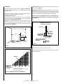
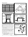
Figure 2a - Minimum Side Clearances to Combustibles
Ceiling clearance: The ceiling must be at least 40" from the top of the
firebox opening (Figure 2).
Noncombustible material: Noncombustible materials, such as slate and
marble, must be at least 1/2" thick and may be used without restriction
above the firebox opening, to the sides or as a hearth extension, so long
as they do not obstruct vent openings for heat circulating models.
NOTE: To avoid heat-related finish damage, we recommend the use
of high temperature paint (rated 175° F or higher) on the underside
of the mantel.
Clearances
Ensure the minimum clearances shown in Figures 2 through 4 are
maintained. Left and right clearances are determined when facing the
front of the firebox.
Follow these instructions carefully to ensure safe installation. Failure to
follow these requirements may create a fire hazard.
Combustible Side Clearances:
Clearances from the side of the firebox opening to any combustible
material (e.g. side wall, mantel leg, bookshelf, etc.), must comply with
the requirements shown in Figures 2 and 2a.
Example: If the mantel leg, bookshelf or other combustible material
protrudes 5" from the plane of the wall where the firebox is installed,
the combustible material must be a minimum of 6" from the side of the
firebox opening (see Figure 2a).
Figure 2
Combustible Wall Clearance
Above Appliance (all models)
Figure 3
Top View
13”
45°
11”
9”
7”
6”
5”
4”
3”
2”
4”
3”**
5”
6”
7”
8”
10”
12”
14”
16”*
Example
* Minimum 16” from Side Wall
**No combustible material may be closer than 3”
from the fireplace opening.
Maintain adequate clearances around air openings.
Maintain adequate clearances for accessibility for purposes of servicing
and proper operation.

NOTE: DIAGRAMS & ILLUSTRATION ARE NOT TO SCALE.
7
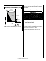
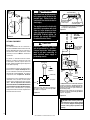
Noncombustible material (minimum requirements) with wood mantel
or other combustible projections: To install the firebox with a wood
mantel, shelf or other combustible projection above firebox opening.
Refer to Figure 4.
Minimum clearence requirements include any projections such as
shelves, window sills, mantels, etc., above the appliance.
If your mantel profile is unsafe, you may either:
• Raise the mantel to an acceptable
height, or
• Remove the mantel.
Floor clearance: These fireplaces may sit directly on a combustible surface.
The appliance should be mounted on a fully supported base extending
the full width and depth of the unit. The appliance may be located on or
near conventional construction materials. However,
if installed on combustible materials, such as carpeting, vinyl tile, etc., a metal
or wood barrier covering the entire bottom surface must be used.
Combustible Mantel and Trim Clearance
Models VRT2536WS and VRT2542WS WITH Hood Installed
Hood is required on all installations for this model only.
s
EXAMPLE: If you choose to install a mantel that projects 5", you will need to
install it so that the bottom of the mantel and trim is approximately 13" or more
above Firebox opening (see coordinate in shaded area above).
Figure 4
16”
17”
18”
9”
3”
4”
5”
6”
7“
8”
10”
11”
12”
13”
14”
15”
Top of Firebox Opening
Screen
Top of Appliance
Combustible
Material (wall)
Combustible Mantel
and Trim
Header
Top Spacer
on Appliance
Safe Zone
Non-Combustible
Material 3” Min.
sExample
s
Example
Coordinate
in (s)Example
s
Hood
WARNING
The hood must be in place to be in compliance with
the clearances specified in Figure 4. Do not remove
or replace hood, only use hood supplied or offered for
these fireboxes (see Pages 16 and 17). Do not use any
hood which may be provided with the decorative type
Vent-Free room heater.

NOTE: DIAGRAMS & ILLUSTRATION ARE NOT TO SCALE.
8
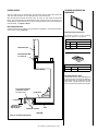
Consult all local codes.
Properly size and route the gas supply line
from the supply regulator to the area where the
appliance is to be installed per requirements
outlined in the National Fuel Gas Code, NFPA
54 - latest edition (USA) or B149 - latest edition
(Canada). Never use galvanized or plastic pipe.
Gas lines must be routed, constructed and made
of materials that are in strict accordance with
local codes and regulations. We recommend
that a qualified individual such as a plumber
or gas fitter be hired to correctly size and route
the gas supply line to the appliance. Installing
a gas supply line from the fuel supply to the
appliance involves numerous considerations of
materials, protection, sizing, locations, controls,
pressure, sediment, and more. Certainly no one
unfamiliar and unqualified should attempt sizing
or installing gas piping.
Remove the gas line access cover plate on either
the left or right side of the fireplace (see Figure
6 showing locations).
Install 1/2" min. to 1-1/2" max. inside diameter
approved gas line through the firebox wall for
connection to the Vent-Free room heater inside
the firebox. Connect the gas line before the
firebox is enclosed in the finished wall. Gas line
holes and other openings should be caulked with
high temperature caulk or stuffed with unfaced
fiberglass insulation.
Ensure that a sediment trap is installed in the
existing gas line, if not, install a sediment trap
upstream of the heater to prevent moisture and
contaminants from passing through trap to the
heater controls and burners. Failure to do so
could prevent the heater from operating reliably.
An external regulator must be used on all pro-
pane (L.P.G). heaters, in addition to the regulator
fitted to the heater, to reduce the supply tank
pressure to 13" W.C. (maximum). Any copper
tubing used to supply propane (L.P.G). from
the tank must be internally tinned.
INSTALLATION
Gas Line Installation
ASSEMBLY STEPS
NOTES:
• Illustrations shown in this manual reflect
“typical” installations with nominal dimen-
sions and are for design and framing refer-
ence only. Actual installations may vary due
to individual design preferences. However,
always maintain minimum clearances to
combustible materials and do not violate any
specific installation requirements. Refer to
the Framing Specifications Figures on Page
11.
• The following steps represent the normal
sequence of installation. Each installation
is unique, however, and might require a
different sequence.
Step 1. Position firebox prior to framing or
into prepared framing.
Step 2. Field wire the main power supply to
the appliance if a blower kit is to be installed
(at the time of installation or a later date).
An optional junction box kit and blower kit is re-
quired (see Page 15
for ordering information).
Follow the installation and wiring instructions on
Pages 12 through 14). Electrical connections
should only be performed by an experienced,
licensed/certified tradesman.
Step 3. Plumb gas line. (Gas connections
should only be performed by an experienced,
licensed/certified tradesman).
Step 4. Install decorative type Vent-Free room
heater per the instructions provided with the
Vent-Free room heater.
Step 5. Complete finish wall material, sur
-
round and optional hearth extension to your
individual taste.
TEST ALL CONNECTIONS FOR GAS LEAKS
(FACTORY AND FIELD)
Test all gas joints from the gas meter to the gas
heater regulator for leaks using a gas leak test
solution (also referred to as bubble leak solution).
NOTE: Using a soapy water solution as a leak
detection solution is not recommended because
the soap residue that is left on the pipes/fittings
can result in a false-positive leak detection reading
if a gas leak sniffer is used. Soap residue can also
result in corrosion over time.
DO NOT USE AN OPEN FLAME TO CHECK
FOR LEAKS.
Leak Test Procedure:
Turn on gas supply and test for gas leaks using
a gas leak test solution.
A. Light the appliance (refer to the lighting
instructions label provided with gas logs).
B. Brush all joints and connections with the gas
leak detection solution. If bubbles are formed,
or gas odor is detected, turn the gas control
knob (off/pilot/on) to the “OFF” position. Either
tighten or refasten the leaking connection, then
retest as described above.
C. When the gas lines are tested and found to
be leak free, rinse off the leak testing solution
from gas line fittings.
WARNING
Connecting directly to an unregu-
lated propane (L.P.G.) tank can
cause an explosion.
CAUTION
Plumbing connections should
only be performed by a qualified,
licensed plumber. Main gas supply
must be off when plumbing gas line
to fireplace or performing service.
IMPORTANT
Hold heater regulator with a wrench
to prevent movement when connect-
ing to inlet piping.
WARNING
Check Gas Type: The gas supply
must be the same as stated on the
heater’s rating plate. If the gas
supply is different, DO NOT INSTALL
the heater. Contact your dealer for
the correct model.
IMPORTANT
Pack unfaced fiberglass insulation
material (not provided) around the
gas line access hole on appliance
and all exterior gas line penetra-
tion holes.

NOTE: DIAGRAMS & ILLUSTRATION ARE NOT TO SCALE.
Figure 5
8d Nail or equivalent
nail or screw
Top Spacer
9
The firebox may be positioned and then the
framing built around it, or the framing may
be constructed and the firebox positioned into
the opening.
Usually, no special floor support is needed for
the firebox, however, to be certain:
1. Estimate the total weight of the firebox
system and surround materials such as
marble, brick, stone, etc., to be installed
(see Product Referance Table on Page 10
for appliance weight).
2. Measure the square footage of the floor
space to be occupied by the system and
surrounds.
3. Note the floor construction, i.e. 2" x 6", 2" x
8" or 2" x 10", single or double joists, type
and thickness of floor boards.
4. Use this information and consult your lo-
cal building code to determine if you need
additional support.
If you plan to raise the firebox, build the plat-
form assembly then position firebox on top.
Secure the platform to the floor to prevent
possible shifting.
Firebox Installation
Step 1. Frame these appliances as illustrated in
Figures 7 through 9. All framing details must
allow for a minimum clearance to combustible
framing members as shown in Figures 2
through 4. Also refer to appliance specifications
on Page 10 . Headers may be in direct contact
with the appliance top spacers but must not
be supported by them or notched to fit around
them. All construction above the appliance
must be self supporting, DO NOT USE THE
APPLIANCE FOR STRUCTURAL SUPPORT.
NOTE: The framed depth from a framed wall,
must always be measured from a finished
surface. If a wall covering such as drywall is
to be attached to the rear wall, then the depth
must be measured from the drywall surface.
It is important that this dimension be exact.
Step 2. Level the firebox by checking the top
edge of the firebox. Shim if necessary.
Step 3. Fireplace should be secured to side
framing members using the full length nailing
tabs at the top and bottom of the fireplace front
face. Use 8d nails (see Figure 5).
Firebox Framing
Construct firebox framing following Figures 7
through 9 and Table 1 on Page 11 for your
specific installation requirements. Refer to
Figure 6 on Page 10 for firebox dimensions.
The firebox may be installed directly on a
combustible floor or raised on a platform of
an appropriate height. When the appliance is
installed directly on carpeting, vinyl tile (other
than ceramic) or other combustible material,
other than wood flooring, the appliance shall
be installed on a metal or wood panel extending
the full width and depth of the appliance. Be
sure firebox rests on a solid continuous floor or
platform with appropriate framing for support
and so that no cold air can enter room from
under the firebox.
NOTE: The nailing flange and the area directly
behind the nailing flange is exempt from the
clearances described on the firebox clearance
label.
Step 4. To safely operate the heater with con-
sideration of the mantel clearances the hood
must be installed (Models VRT2536WS and
VRT2542WS Only).
CAUTION
Do not block the heat-circulating
air inlets and outlets on these
fireboxes. Doing so may create a
potential fire hazard.
IMPORTANT
Under no circumstances shall the
firebox top spacers be removed or
modified (see Figure 6). The header
may be in direct contact with the top
spacers but must not be supported
by them, notched or altered to fit
around them.

NOTE: DIAGRAMS & ILLUSTRATION ARE NOT TO SCALE.
10
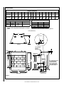
Figure 6
SPECIFICATIONS
Gas Line
Access -
Both Sides
Access Opening for Junction
Box - Right Side Only
(remove the knock-out
before installing J-Box).
J-Box / Electrical Kit is not
provided with appliance.
Junction Box
Top View
A
E
C
D
P
*Q
F
H
J
M
N
1 (26)
7-1/8
(181)
Front View
B
G
Right Side View
L
K
Top Stand-Off
Spacers
(4 places)
5-3/4
(146)
3-5/8
(94)
Bottom of
Firebox
Opening
Top of Firebox
Opening
* Hood
Product Reference Information
Cat. No. Model Ship. Weight (lbs) Shipping Volume
F0322 VRT2536WS 150 lbs
20 Cu. Ft.
F3304 VRT2542WS 130 lbs
24 Cu. Ft.
Fireplace Dimensions
Model No. A B C D E F G H J K L M N P *Q
VRT2536WS
36
(914)
24
(610)
41-3/4
(1061)
37-1/4
(946)
23-1/2
(597)
20
(508)
3
(76)
7-3/8
(187)
15-7/8
(403)
7-1/2
(190)
12
(305)
1-3/8
(35)
5-1/2
(140)
30-3/8
(772)
29-5/8
(753)
VRT2542WS
42
(1067)
24
(610)
47-3/4
(1213)
37-1/4
(947)
29-1/2
(749)
20
(508)
3
(77)
7-3/8
(188)
15-7/8
(404)
7-1/2
(191)
12
(305)
1-3/8
(35)
5-1/2
(140)
30-3/8
(772)
29-5/8
(753)
* *Dimensions are to assist you in selecting a log set that is a compatible size.
* The factory-supplied hood must be installed on the firebox for safe
operation for models VRT2536WS and VRT2542WS in ALL INSTAL-
LATIONS.
Interior Firebox Dimensions**
Firebox Model 36” 42”
Front Width 35 (889) 41 (1042)
Rear Width 23-1/4 (591) 29-1/4 (743)
Depth 17-3/8 (441) 17-3/8 (441)
Height 24 (610) 24 (610)
Inches (millimeters)

NOTE: DIAGRAMS & ILLUSTRATION ARE NOT TO SCALE.
11
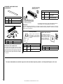
FRAMING SPECIFICATIONS
Figure 7
Hood Kit Installation (see ordering information on Page 16)
The firebox canopy (hood) shall not be modified or replaced with a
canopy that may be provided with the unvented decorative room
heater.
NOTE: A hood comes standard and is required for models VRT2536WS
and VRT2542WS. The factory-supplied hood must be installed on the
firebox for safe operation for models VRT2536WS and VRT2542WS in
all installations. See
Figure 11.
These hood kits are design to be fitted to the face of the appliance directly
above the firebox opening. In addition to providing an aesthetically pleasing
appearance to your appliance, the hood reduces heat effects to decora-
tive mantels and finish materials located directly above the fireplace and
reduces the Mantel / Trim clearances (see Figure 4 on Page 7).
Please read this entire manual and understood thoroughly before proceeding
with the installation of these kits.
Step 1. Using a 5/16" nut driver or socket, remove the screen and rod
assemblies as shown in Figure 10.
Step 2. Align the hood with the holes in the side frames as shown in
Figure 11. Install three screws as shown in Figure 11. Make
sure hood is level and secure.
Step 3. Reinstall screen and rod assemblies (see Figure 10).
Framing Dimensions
Opening VRT2536WS VRT2542WS
A 42-1/4" (1073) 48-1/4" (1226)
B 40-1/4" (1022) 40-1/4" (1124)
C 23-5/8" (600) 29-5/8" (753)
D 11-1/4" (286) 15-1/4 (387)
E 63-1/2" (1613) 69-3/4 (1772)
F 31-3/4" (807) 34-7/8 (886)
G * 20-1/2"( 521) 20-1/2"( 521)
H 44-1/4" (1124) 49-3/8 (1254)
Table 1 - This Table corresponds to Figures 7, 8 and 9
Rough Framing Face
(Unfinished Shown)
Back Wall Of Chase/Enclosure
Including Finishing Materials If Any
Rough Framing Face
(Unfinished Shown)
A
C
G
Parallel Installation
Figure 8
Figure 9
This Figure cor-
responds to Table 1
This Figure corresponds
to Table 1
WARNING: Do not fill
spaces around the
firebox with insulation
or other materials.
A
B
Header
Figure 10
Removing Screens and Rods:
Remove screws (see dotted
lines). Pull out rods from
locating holes on side of firebox
opening.
Reinstalling Screens and Rods:
Insert rods into corresponding
locating holes on sides of firebox
opening, then reinstall screws
as shown.
A
C
D
H
F
G
E
Back Wall Of Chase/Enclosure
Including Finishing Materials If Any
Rough Framing Face
(Unfinished Shown)
Corner Installation
This Figure corresponds to Table 1
* Back wall of chase/enclosure including finishing materials, if any.

NOTE: DIAGRAMS & ILLUSTRATION ARE NOT TO SCALE.
12
OPTIONAL EQUIPMENT
Blower Kits
The FBK-100 Blower Kits are used when a
wall-mounted ON/OFF blower switch is desired,
and the FBK-200 Blower Kits are used when a
wall-mounted variable speed blower control
(rheostat) is desired. NOTE: A Junction Box
is provided.
The blower is installed beneath the firebox.
Room air is drawn in through the side slots
of the fireplace, heated as it passes across the
firebox, and discharged through the upper area
of the firebox opening.
The installation instructions for installing these
blower kits are on Pages 12 through 14. Also
see the installation instructions provided with
the blower kits (Form #750028M). For electrical
requirements, refer to Figures 12, 13 and 14.
If the blower kit is to be installed at the time of
installation or at a later date, the main power
supply must be installed at the time of instal-
lation. This will require that the electrical
connections must be made BEFORE the firebox
is framed and enclosed in the finished walls.
Route a 3-wire, 120 VAC, 60 Hz, 1 ph power
supply and connect to electrical receptacle wires
and wall switch or rheostat.
Grounded
to Appliance
Blower Motor
Motor Plug
Receptacle
120V
Appliance Junction Box
NOTE: If any of the original wire as supplied
must be replaced, it must be replaced with type
AWM 105°c – 18Ga. wire
120V, 60HZ,
1PH BLOWER
CONTROL CIRCUIT
WIRING
Junction
Box
Factory Wired
Blower
Tab
Intact
Plug blower
into this
receptacle
Ground - Green
* Wall-mounted ON/
OFF Blower Switch
or Variable Speed
Control Switch.
Ground
HOT SIDE OF
RECEPTACLE
*An ON/OFF Wall Switch is used with the FBK-100 kit (field
provided or sold separately - order P/N 85L87); A Variable
Speed Control (provided) is used with the FBK-200 kit. The
installation of these kits also require a Junction Box /
Electrical Kit (provided).
NOTE: If any of the original wire as supplied must
be replaced, it must be replaced with type AWM 105
degree C - 14 gage wire.
Neutral - White
120 VAC Black
Green
Ground
Screw
NEUTRAL
SIDE OF
RECEPTACLE
Black
Field Wired
Figure 14
Blower
* Junction Box
Bend blower mounting
tabs up to secure
blower in place
* Electrical Outlet
Tie a loose knot in power
cord to take up slack
Top View
Figure 13
Figure 12
NOTE: If any of the original wire as supplied must
be replaced, it must be replaced with type AWM
105 degree C - 14 gage wire.
* The Junction Box / Electrical Kit is not included.
See Page 15 for ordering information.
Figure 11
Hood
Side View
IMPORTANT
The Ground Lead must be connected
to the green screw (located on the
junction box). Failure to do this
could result in an electrical short or
shock injury.
The appliance must be electrically
grounded in accordance with local
codes or, in the absence of local
codes, the national electrical code,
ANSI/NFPA 70-latest edition. (In
Canada, the current CSA C22.1
Canadian Electrical Code).
CAUTION
Electrical connections should
only be performed by a qualified,
licensed electrician. Main power
must be off when connecting to
main electrical power supply or
performing service.
CAUTION: Label all wires prior to dis-
connection when servicing controls. Wiring
errors can cause improper and dangerous
operation. Verify proper operation after
servicing.

NOTE: DIAGRAMS & ILLUSTRATION ARE NOT TO SCALE.
13
Step 1. Follow the instructions below for the model you are installing:
Models VRT2536WS and VRT2542WS:
Using a screwdriver remove the screw from the blower access panel
as shown in Figure 15. Slide the panel to the right until the flange
clears the opening. Remove the panel and set aside.
Step 2. Remove the rectangular knock-out (for J-Box) on the right side
of unit (see Figure 6 for location). Install the Junction Box and Electrical
outlet below the firebox floor into the rectangular opening on the right
side cabinet panel where you removed the knock-out (see Figures 16
and 17). The Junction Box / Electrical Kit is sold separately (see Page
15 for ordering information).
• Squeeze the J-Box flanges together to fit into the opening shown in
Figures 17 and 18.
• Wires will need to be passed through the hole shown in Figure 16.
• An approved strain relief bushing (not supplied with the kit), is required
to restrain the wires (see Figure 16).
Step 3. Loosely tie a knot in the power cord to take up slack (see Figure 19).
Step 4. Locate the tabs shown in Figure 20. Position the blower assembly
so that the tabs (located on the cabinet base) are seated in the notches of
the blower bracket. Bend the tabs over to secure the blower assembly (see
Figure 21).
Step 5. Plug power cord into the electrical outlet as illustrated in Figure 13.
J-Box Flanges
J-Box and
Electrical
Outlet
Right Outside Cabinet Panel
Wires
Figure 17
Figure 15 -
Models VRT2536WS and VRT2542WS
Figure 18
IMPORTANT
All electrical wiring must be performed by licensed Elec-
tricians. Electrical wiring must comply with the National
Electrical Code ANSI/ NFPA 70 - latest edition
Installation Instructions -
FBK-100 or FBK 200 Blower Kits and JBK Junction Box Kit
Firebox
floor
Blower
Access
Panel
Remove screw, then lift out blower access panel.
J-Box Flange
Install into side wall rectanular opening
Firebox
floor
Screw
Figure 16 - Junction Box Kit (all models)
J-Box and
Receptacle
J-Box and Electrical Outlet
Screw
Remove knock-out
(strain relief bush-
ing [not supplied]
presses into this
hole around romex
wires - see Step 8 on
Page 14).
Cover Plate

NOTE: DIAGRAMS & ILLUSTRATION ARE NOT TO SCALE.
14
Step 8. Ensure that power supply wires are NOT "live" before making
these connections). Install J-Box Cover Plate as follows:
Feed the * Romex wires (or other equivalent plastic insulated
wire - Refer ANSI/NFPA 70 - National Electrical Code - Latest
Edition) through the J-Box Cover rectangular opening, then con-
nect to the J-box wires. The strain relief bushing (not supplied)
should be pressed into the knock-out on J-box cover around the
Romex (this will provide protection to the wires and prevents strain
against connections from J-box). See Wiring Diagram - Figure
14. Install the cover plate over J-Box opening on appliance as
shown in Figure 22.
NOTE: Wire connections should be positioned inside of the ap-
pliance.
* Romex is a plastic insulated wire from power supply - sometimes called
non-metallic sheath.
Cabinet Base
Figure 19
Figure 20
Figure 21
Loose knot in power
cord to take up slack
Firebox
floor
Locating Tabs
Bend Locating Tabs Over
(into notches)
Use screw provided and
secure in place as shown
The notched side of
cover plates goes inside
firebox panel
Screw
Cover Plate
Right Side Panel of Firebox
Figure 22 - Installing J-box Cover Plate - All Models
Step 9. Follow the instructions below for the kit you are installing:
FBK-100 Kits - Install a field-provided (or P/N 85L87) ON/OFF wall
switch in a convenient location on a wall, near the fireplace.
FBK-200 Kits - Install the kit-provided variable speed control
(rheostat) in a convenient location on a wall, near the fireplace.
Step 10. Follow the instructions below for the model you are installing:
Models VRT2536WS and VRT2542WS:
Reinstall the blower access panel that was removed on Step 1 (see
Figure 15).
J-Box opening
on appliance
Step 6. Route a 3-wire, 120 VAC, 60 Hz, 1 ph power supply to the right
side of appliance.
Step 7. Locate the J-Box cover (provided in J-Box Kit). Remove the round
knock-out (see Figure 16).

NOTE: DIAGRAMS & ILLUSTRATION ARE NOT TO SCALE.
15
FIREBOX FINISHES
There are a wide variety of “finished looks” for your built-in Vent-Free firebox from formal wall
decor with elaborate mantels to rustic wood paneling or warm brick facings.
Only noncombustible materials like marble, stone, tile, brick, etc. may overlap the black front
facing. Seal all joints between the black facing and wall surrounds to prevent air intrusion. Use
noncombustible caulking material only to seal the black metal facing to the surround material on
the finished wall. See Figures 3 and 23.
Raised Hearth Extension
A hearth extension may be used but is not required for these appliances. A raised hearth extension
may be used as shown in Figure 23.
Raised Hearth Extension
(combustibles allowed.
No carpet or vinyl)
Combustible Platform
SIDE VIEW
Firebox Floor
Combustible Wall
Figure 23 - Raised Hearth Extension
Non-Combustible Wall
(see Figure 4)
Fireplace Opening
* From Base to
Bottom of Firebox
Opening (floor)
5-3/4" Max.*
Base
APPROVED ACCESSORIES AND
COMPONENTS
Decorative Volcanic Stone
The decorative volcanic stone, Model FDVS, can
be used to enhance the look of your appliance.
Order model FDVS for replacement of stone
when needed. Spread the decorative volcanic
stone evenly around the bottom of the firebox.
(ref. Form #750010M)
Decorative Volcanic Stone
Cat. No. Model No. Description
80L42 FDVS Bag of Volcanic Stone
Decorative Screen Door Panel Kit
Cat. No. Model Where Used
H1959 ASD3624-TI VRT2536WS
F3362 ASD4224-TI VRT2542WS
Decorative Arch Screen Panel Kit
This attractive screen door is easy to install and
enhances the appearance of the appliance.
(ref. Form #750209M)

NOTE: DIAGRAMS & ILLUSTRATION ARE NOT TO SCALE.
16
Outside Air Gate and Duct Kit
Cat. No. Model No. Description
H3991 OAK-UVFRC Outside Air Gate and Duct Kit
Outside Air Gate and Duct Kit
These kits have an air gate assembly, 4" diam-
eter duct and a termination hood. The air gate
allows adjustment of the amount of outside air
delivered to the fire for combustion. Only one
kit, located on the right side of the fireplace,
is required.
(ref. Form #750206M)
Blower Kit
The FBK-100 blower provides for a constant velocity forced air circulation feature for your ap-
pliance. The FBK-200 assembly with variable speed wall switch provides a forced air circulation
feature for your appliance.
Black Hood
Cat. # Model Models Where Used
H1989 FC36
VRT2536WS (standard part)
H1990 FC42
VRT2542WS (standard part)
* Forced Air Blower Kits
Cat.
No.
Model No. Description
80L84 FBK-100
Blower, Standard
(single speed)
80L85 FBK-200
Blower, Variable Speed
(w/wall-mounted switch)
Touch-Up Paint Kit
Repair of minor scratches and
discoloration of the appliance
black painted surfaces may be
accomplished with the touch-up
paint kit.
P
A
I
N
T
The variable speed control
rheostat is included with
FBK-200 models only
An ON/OFF wall switch can be used
with the FBK-100 models (field
supplied or order P/N 85L87 Wall
Switch Kit, shown below)
ON/OFF Wall Switch Kit
The ON/OFF wall switch kit
may be used to control the
blower operation, if FBK-
100 blower kit is installed.
Install the ON/OFF wall
switch in a convenient
location near the fireplace.
White Wall Switch Kit
Cat. No. Model No. Description
85L87 FWSK ON/OFF Wall Switch Kit
* The installation of these kits also require a Junction Box / Receptacle
Kit, not included. See ordering information on this Page.
(ref. Form #750195M)
APPROVED ACCESSORIES AND
COMPONENTS
For more information on available log sets for this and other Superior products, visit SuperiorFireplaces.Us.com.
Touch-Up Paint Kit
Cat. No. Model No. Description
F1882 SCTPSAB
Black touch-up paint, powder
coat (for firebox face and hood)
F3373 ---
Black touch-up paint, Firebox
Interior

NOTE: DIAGRAMS & ILLUSTRATION ARE NOT TO SCALE.
17
No. Description
VRT2536WS
Cat. No. F0322
VRT2542WS
Cat. No. F3304
Cat. No. Qty. Cat. No. Qty.
1 Firescreen H2325 2 H2699 2
2 Rod, Screen H3919 2 H2700 2
3 Refractory Panel Set, 3 pc. F3378 1 F3380 1
3a Refractory, Left (order set) -- 1 -- 1
3b Refractory, Right (order set) -- 1 -- 1
3c Refractory, Rear (order set) -- 1 -- 1
4 Hood H1989 1 H1990 1
5 Junction Box Assembly H6048 1 H6048 1
REPLACEMENT PARTS
3
4
5
2
1
6
3
4
5
WARNING
Failure to position the parts in accordance with these
diagrams or failure to use only parts specifically
approved with this appliance may result in property
damage or personal injury.
An exploded view of the firebox with numbered parts and a replacement
parts list can be found on the Page. Normally, all parts should be ordered
through your distributor or dealer. Parts will be shipped at prevailing
prices at time of order.
NEVER USE SUBSTITUTE MATERIALS. USE OF NON-APPROVED PARTS
CAN RESULT IN POOR PERFORMANCE AND SAFETY HAZARDS.
When ordering repair parts, always give the following information:
1. The *model number of the firebox.
2. The *serial number of the firebox.
3. The part number.
4. The description of the part.
5. The quantity required.
6. The installation date of the firebox.
* NOTE: The model and serial number can be found on the rating label
located on the bottom left front corner of the appliance.
If you encounter any problems or have any questions concerning the
installation of a Vent-Free heater in this system, please contact your dis-
tributor or dealer or visit our website at IHP.us.com for referral information.
3b
3a
3c
3
WARNING
REFRACTORY PANELS
LIFTING HAZARD
SINGLE - PERSON LIFT
COULD CAUSE INJURY.
USE ASSISTANCE WHEN
MOVING OR LIFTING.
3
4
5
2
1
6
3
4
5
4
5

18
______________________________________________________
______________________________________________________
______________________________________________________
______________________________________________________
______________________________________________________
______________________________________________________
______________________________________________________
______________________________________________________
______________________________________________________
______________________________________________________
______________________________________________________
______________________________________________________
______________________________________________________
______________________________________________________
______________________________________________________
______________________________________________________
______________________________________________________
______________________________________________________
______________________________________________________
______________________________________________________
______________________________________________________
______________________________________________________
______________________________________________________
______________________________________________________
______________________________________________________
______________________________________________________
______________________________________________________
______________________________________________________
______________________________________________________
______________________________________________________
______________________________________________________
______________________________________________________
______________________________________________________
______________________________________________________
______________________________________________________
______________________________________________________
______________________________________________________
NOTES

19
Printed in U.S.A. © 2013 Innovative Hearth Products
P/N 900223-00, Rev. C 02/2018
Innovative Hearth Products
1769 East Lawrence Street • Russellville, AL 35654
Innovative Hearth Products
Superior
®
Brand Gas Fireplaces, Stoves and Inserts
20 Year Limited Warranty
THE WARRANTY
Innovative Hearth Products ("IHP") 20 Year Limited Warranty warrants your Superior
®
Brand gas fireplace, Stove or Insert ("Product") to be free from defects in materials
and workmanship at the time of manufacture. The product body, firebox and barrier carry the 20 Year Limited Warranty. Ceramic glass carries the 20 Year Limited Warranty
against thermal breakage only. After installation, if covered components manufactured by IHP are found to be defective in materials or workmanship during the 20 Year
Limited Warranty period and while the Product remains at the site of the original installation, IHP will, at its option, repair or replace the covered components. If repair or
replacement is not commercially practical, IHP will, at its option, refund the purchase price or wholesale price of the IHP product, whichever is applicable. IHP will also
pay IHP prevailing labor rates, as determined in its sole discretion, incurred in repairing or replacing such components for up to five years. THERE ARE EXCLUSIONS AND
LIMITATIONS to this 20 Year Limited Warranty as described herein.
COVERAGE COMMENCEMENT DATE
Warranty coverage begins on the date of purchase. In the case of new home construction, warranty coverage begins on the date of first occupancy of the dwelling or six
months after the sale of the Product by an independent IHP dealer/distributor, whichever occurs earlier. The warranty shall commence no later than 24 months following
the date of product shipment from IHP, regardless of the installation or occupancy date.
EXCLUSIONS AND LIMITATIONS
This 20 Year Limited Warranty applies only if the Product is installed in the United States or Canada and only if operated and maintained in accordance with the printed
instructions accompanying the Product and in compliance with all applicable installation and building codes and good trade practices.
This warranty is non-transferable and extends to the original owner only. The Product must be purchased through a listed supplier of IHP and proof of purchase must be
provided. The product body, firebox and barrier carry the 20 Year Limited Warranty from the date of installation. Vent components, trim components and paint are excluded
from this 20 Year Limited Warranty. The following do not carry the 20 Year Limited Warranty but are warranted as follows:
Burner – Repair or replacement for one year from the date of installation
Gas components – Repair or replacement for one year from the date of installation
Gaskets – Repair or replacement for one year from the date of installation
Logs – Replacement for one year from the date of installation against thermal breakage only
Optional blowers & remote controls – Repair or replacement for one year from the date of installation
Optional glass doors – Repair or replacement for 90 days from the date of installation
Tempered glass - Replacement for one year from the date of installation
Labor coverage – Prevailing IHP labor rates apply for the warranty period of the component
Parts not otherwise listed carry a 90 day warranty from the date of installation.
Whenever practicable, IHP will provide replacement parts, if available, for a period of 10 years from the last date of manufacture of the Product.
IHP will not be responsible for: (a) damages caused by normal wear and tear, accident, riot, fire, flood or acts of God; (b) damages caused by abuse, negligence, misuse, or
unauthorized alteration or repair of the Product affecting its stability or performance (The Product must be subjected to normal use. The Product is designed to burn either
natural or propane gas only. Burning conventional fuels such as wood, coal or any other solid fuel will cause damage to the Product, will produce excessive temperatures
and could result in a fire hazard.); (c) damages caused by failing to provide proper maintenance and service in accordance with the instructions provided with the Product;
(d) damages, repairs or inefficiency resulting from faulty installation or application of the Product.
IHP is not responsible for inadequate fireplace system draft caused by air conditioning and heating systems, mechanical ventilation systems, or general construction condi-
tions which may generate negative pressure in the room in which the appliance is installed. Additionally IHP assumes no responsibility for drafting conditions caused by
venting configurations, adjoining trees or buildings, adverse wind conditions or unusual environmental factors and conditions that affect the operation of the unit.
This 20 Year Limited Warranty covers only parts and labor as provided herein. In no case shall IHP be responsible for materials, components or construction, which are not
manufactured or supplied by IHP or for the labor necessary to install, repair or remove such materials, components or construction. Additional utility bills incurred due to
any malfunction or defect in equipment are not covered by this warranty. All replacement or repair components will be shipped F.O.B. from the nearest stocking IHP factory.
LIMITATION ON LIABILITY
It is expressly agreed and understood that IHP’s sole obligation and the purchaser’s exclusive remedy under this warranty, under any other warranty, expressed or implied,
or in contract, tort or otherwise, shall be limited to replacement, repair, or refund, as specified herein.
In no event shall IHP be liable for any incidental or consequential damages caused by defects in the Product, whether such damage occurs or is discovered before or
after repair or replacement, and whether such damage is caused by IHP’s negligence. IHP has not made and does not make any representation or warranty of fitness for a
particular use or purpose, and there is no implied condition of fitness for a particular use or purpose.
IHP makes no expressed warranties except as stated in this 20 Year Limited Warranty. The duration of any implied warranty is limited to the duration of this expressed warranty.
No one is authorized to change this 20 Year Limited Warranty or to create for IHP any other obligation or liability in connection with the Product. Some states and provinces
do not allow the exclusion or limitation of incidental or consequential damages, so the above limitations or exclusions may not apply to you. The provisions of this 20 Year
Limited Warranty are in addition to and not a modification of or subtraction from any statutory warranties and other rights and remedies provided by law.
INVESTIGATION OF CLAIMS AGAINST WARRANTY
IHP reserves the right to investigate any and all claims against this 20 Year Limited Warranty and to decide, in its sole discretion, upon the method of settlement.
To receive the benefits and advantages described in this 20 Year Limited Warranty, the appliance must be installed and repaired by a licensed contractor approved by IHP.
Contact IHP at the address provided herein to obtain a listing of approved dealers/distributors. IHP shall in no event be responsible for any warranty work done by a
contractor that is not approved without first obtaining IHP's prior written consent.
HOW TO REGISTER A CLAIM AGAINST WARRANTY
In order for any claim under this warranty to be valid, you must contact the IHP dealer/distributor from which you purchased the product. If you cannot locate the dealer/
distributor, then you must notify IHP in writing. IHP must be notified of the claimed defect in writing within 90 days of the date of failure. Notices should be directed to the
IHP Warranty Department at 1769 East Lawrence Street; Russellville, AL 35654 or visit our website at WWW.SUPERIORFIREPLACES.US.COM.
10/14/2015

Printed in U.S.A. © 2017 Innovative Hearth Products
P/N 900853-00 REV. D 12/2020
Innovative Hearth Products (IHP) reserves the right to make changes at any time, without
notice, in design, materials, specifications, prices and the discontinuance of colors, styles and
products. Consult your local distributor for fireplace code information.
1769 East Lawrence Street • Russellville, AL 35654
P900853-00
-
 1
1
-
 2
2
-
 3
3
-
 4
4
-
 5
5
-
 6
6
-
 7
7
-
 8
8
-
 9
9
-
 10
10
-
 11
11
-
 12
12
-
 13
13
-
 14
14
-
 15
15
-
 16
16
-
 17
17
-
 18
18
-
 19
19
-
 20
20


Superior Fireplaces VRE3200 Operating instructions
- Category
- Stoves
- Type
- Operating instructions
- This manual is also suitable for
Ask a question and I''ll find the answer in the document
Finding information in a document is now easier with AI
Related papers
-
Superior Fireplaces VRT3100 Operating instructions
-
Superior VRT2500 Operating instructions
-
-
-
Superior VRT6042RH Operating instructions
-
-
-
-
-
