Sharp XV-Z17000 Owner's manual
- Category
- Data projectors
- Type
- Owner's manual

XV-Z17000
XV-Z17000
PROJECTOR
PROJECTEUR
PROYECTOR
PROJETOR
Printed in China
Imprimé en Chine
Impreso en China
Impresso na China
TINS-E929WJZZ
11P01-CH-NM
ENGLISH
FRANÇAIS ESPAÑOL PORTUGUÊS
OPERATION MANUAL
MODE D’EMPLOI
MANUAL DE MANEJO
MANUAL DE OPERAÇÃO
SHARP CORPORATION

SPECIAL NOTE FOR USERS IN THE U.K.
The mains lead of this product is fi tted with a non-rewireable (moulded) plug incorporating a 10A fuse.
Should the fuse need to be replaced, a BSI or ASTA approved BS 1362 fuse marked
or and of the
same rating as above, which is also indicated on the pin face of the plug, must be used.
Always refi t the fuse cover after replacing the fuse. Never use the plug without the fuse cover fi tted.
In the unlikely event of the socket outlet in your home not being compatible with the plug supplied, cut
off the mains plug and fi t an appropriate type.
DANGER:
The fuse from the cut-off plug should be removed and the cut-off plug destroyed immediately and dis-
posed of in a safe manner.
Under no circumstances should the cut-off plug be inserted elsewhere into a 13A socket outlet, as a
serious electric shock may occur.
To fi t an appropriate plug to the mains lead, follow the instructions below:
WARNING:
THIS APPARATUS MUST BE EARTHED.
IMPORTANT:
The wires in this mains lead are coloured in accordance with the following code:
Green-and-yellow : Earth
Blue : Neutral
Brown : Live
As the colours of the wires in the mains lead of this apparatus may not correspond with the coloured
markings identifying the terminals in your plug proceed as follows:
• The wire which is coloured green-and-yellow must be connected to the terminal in the plug which is
marked by the letter E or by the safety earth symbol
or coloured green or green-and-yellow.
• The wire which is coloured blue must be connected to the terminal which is marked with the letter N
or coloured black.
• The wire which is coloured brown must be connected to the terminal which is marked with the letter L
or coloured red.
IF YOU HAVE ANY DOUBT, CONSULT A QUALIFIED ELECTRICIAN.

ENGLISH
-1
Before using the projector, please read this operation manual carefully.
WARNING:
To reduce the risk of fi re or electric shock, do not expose this product to rain
or mois ture.
WARNING:
High brightness light source. Do not stare into the beam of light, or view directly. Be especially
careful that children do not stare directly into the beam of light.
CAUTION: TO REDUCE THE RISK OF ELECTRIC SHOCK,
DO NOT REMOVE COVER.
NO USER-SERVICEABLE PARTS EXCEPT LAMP UNIT.
REFER SERVICING TO QUALIFIED SERVICE PERSONNEL.
The lightning fl ash with arrowhead sym bol,
within an equilateral triangle, is in tended to
alert the user to the presence of uninsulated
“dangerous voltage” within the product’s
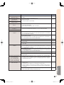
enclosure that may be of suffi cient magnitude
to constitute a risk or electric shock to
persons.
The exclamation point within a triangle is
intended to alert the user to the presence of
important operating and maintenance (servicing)
instructions in the literature accompanying the
product.
Introduction
CAUTION
See bottom of projector.
IMPORTANT
• For your assistance in reporting the loss or theft of
your Projector, please record the Serial Number lo-
cated on the bottom of the projector and retain this
information.
• Before recycling the packag ing, please ensure that
you have checked the con tents of the carton thor-
oughly against the list of “Supplied accessories” on
page 9.
Model No.: XV-Z17000
Serial No.:
RISK OF ELECTRIC SHOCK.
DO NOT REMOVE SCREWS
EXCEPT SPECIFIED USER
SERVICE SCREW.
WARNING:
FCC Regulations state that any unauthorized changes or modifi cations to this equipment not ex-
pressly approved by the manufacturer could void the user’s authority to operate this equip ment.
U.S.A. ONLYU.S.A. ONLY
PRODUCT DISPOSAL
This product utilizes tin-lead solder, and lamp containing a small amount of mercury. Disposal
of these materials may be regulated due to environmental considerations. For disposal or
recycling information, please contact your local authorities, the Electronics Industries Al-
liance: www.eiae.org, the lamp recycling organization www.lamprecycle.org, or Sharp at
1-800-BE-SHARP.
U.S.A. ONLYU.S.A. ONLY
This product contains a CR Coin Lithium Battery which contains Perchlorate Material – special handling may apply,
California residents, See www.dtsc.ca.gov/hazardouswaste/perchlorate/
U.S.A. ONLY
WARNING:
This is a Class A product. In a domestic environment this product may cause radio interference in
which case the user may be required to take adequate measures.

-2
Caution Concerning Lamp Replacement
This projector utilizes a pressurized mercury lamp. A loud sound may indicate lamp failure. Lamp failure can be attributed
to numerous sources such as: excessive shock, improper cooling, surface scratches or deterioration of the lamp due to a
lapse of usage time.
The period of time up to failure largely varies depending on the individual lamp and/or the condition and the frequency of
use. It is important to note that failure can often result in the bulb cracking.
When the lamp replacement indicator and on-screen display icon are illuminated, it is recommended that the lamp be
replaced with a new one immediately, even if the lamp appears to be operating normally.
Should the lamp break, there is also a possibility that glass particles may spread inside of the projector. In such a case, it
is recommended you contact your nearest Sharp Authorized Projector Dealer or Service Center to assure safe operation.
Should the lamp break, the glass particles may spread inside the lamp cage or gas contained in the lamp may be vented
into the room from the exhaust vent. Because the gas in this lamp includes mercury, ventilate the room well if the lamp
breaks and avoid all exposure to the released gas. In case of exposure to the gas, consult a doctor as soon as possible.
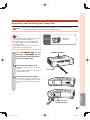
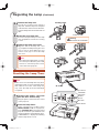
Caution
• Do not remove the lamp unit from the projector right after use. The lamp will be very hot and may cause burns or
injury.
• Wait at least one hour after the power cord is disconnected to allow the surface of the lamp unit to fully cool before
removing the lamp unit.
• Do not touch the glass surface of the lamp unit or the inside of the projector.
• Do not loosen other screws except for the lamp unit cover and lamp unit.
• Make sure to reset the lamp timer only when replacing the lamp. If you reset the lamp timer and continue to use
the same lamp, this may cause the lamp to become damaged or explode.
Carefully change the lamp by following the instructions described on pages 62 to 64.
* If you wish, you may have the lamp replaced at your nearest Sharp Authorized Projector Dealer or Service
Center.
* If the new lamp does not light after replacement, take your projector to the nearest Sharp Authorized Projector
Dealer or Service Center for repair.
INFORMATION
This equipment has been tested and found to comply with the limits for a Class B digital device, pursuant to Part 15
of the FCC Rules. These limits are designed to provide reasonable protection against harmful interference in a resi-
dential installation. This equipment generates, uses, and can radiate radio frequency energy and, if not installed and
used in accordance with the operation manual, may cause harmful interference to radio communications. However,
there is no guarantee that interference will not occur in a particular installation. If this equipment does cause harmful
interference to radio or television reception, which can be determined by turning the equipment off and on, the user
is encouraged to try to correct the interference by one or more of the following measures:
• Reorient or relocate the receiving antenna.
• Increase the separation between the equipment and the receiver.
• Connect the equipment into an outlet on a circuit different from that to which the receiver is connected.
• Consult the dealer or an experienced radio/TV technician for help.
Declaration of conformity
SHARP PROJECTOR, MODEL XV-Z17000
This device complies with Part 15 of the FCC rules. Operation is subject to the following conditions: (1) This device
may not cause harmful interference, and (2) this device must accept any interference received, including interference
that may cause undesired operation.
Responsible Party:
SHARP ELECTRONICS CORPORATION
Sharp Plaza, Mahwah, New Jersey 07495-1163
TEL: 1-800-BE-SHARP (1-800-237-4277)
U.S.A. ONLY
Authorized representative responsible for the European Union Community Market
SHARP ELECTRONICS (Europe) GmbH
Sonninstraße 3, D-20097 Hamburg
E.U. ONLY

Introduction
-3
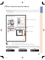
How to Read this Operation Manual
The specifi cations are slightly different, depending on the model. However, you can connect and operate all models
in the same manner.
In this operation manual, the illustration and the screen display are simplifi ed for explanation, and may differ slightly
from the actual display.
•
For Future Reference
Maintenance
P. 59
Troubleshooting
PP. 72 to 74
Index
P. 78
Buttons used in this operation
Info
............ Indicates safeguards for using the projector.
Note
............ Indicates additional information for setting up and operating the projector.
Useful Features
-35
Picture
Picture Mode Standard
High Brightness
On
Off
Contrast
Bright
Color
Tint
Sharp
Red
Blue
CLR Temp
IRIS1 (Manual)
IRIS2 (Auto)
Eco+Quiet
Advanced
Reset
SEL./ADJ.
RETURN
ENTER
END
SIG-ADJ
SCR-ADJ
PRJ-ADJ
0
0
0
0
0
0
0
0
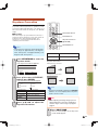
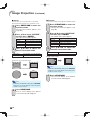
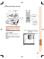
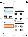
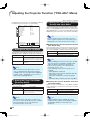
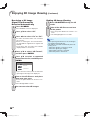
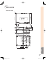
Using the Menu Screen
Menu Selections (Adjust-
ments)
• This operation can also e performed using
the uttons on the pro ector.
1
Press MENU.
• The Picture menu screen for the se-
lected input mode is displa ed.
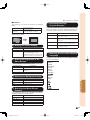
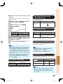
2
Press or to select the menu
screen to adjust on the menu
bar.
1
2
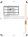
Example: “Picture” menu screen when
COMPONENT is selected for
input mode
RETURN utton
Ad ustment uttons
(///)
ENTER utton
MENU utton
Ad ustment uttons
(///)
Menu bar
ENTER utton
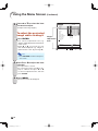
RETURN utton
MENU utton
• Press RETURN
to return to the
previous screen
hen the menu is
displa ed.
_?
?_
?_
Button used in this step
On-screen display

-4
Contents
Preparing
Setup
Setting Up the Projector ...............................16
Setting Up the Projector ...................................... 16
Standard Setup (Front Projection) ........................ 16
Projection (PRJ) Mode ......................................... 17
Ceiling-mount Setup ........................................... 17
Screen Size and Projection Distance ................... 18
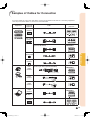
Connections
Samples of Cables for Connection ..............19
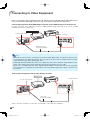
Connecting to Video Equipment ..................20
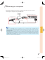
Connecting to a Computer ...........................21
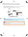
Controlling the Projector by a Computer ....22
Introduction
How to Read this Operation Manual .............3
Contents ...........................................................4
IMPORTANT SAFEGUARDS............................6
Accessories .....................................................9
Part Names and Functions ...........................10
Using the Remote Control ............................13
Inserting the Batteries.......................................... 13
Usable Range ..................................................... 13
Quick Start
Quick Start .....................................................14
Using
Basic Operation
Turning the Projector On/Off ........................23
Connecting the Power Cord ................................ 23
Turning the Projector On ..................................... 23
Turning the Power Off
(Putting the Projector into Standby Mode) ..... 23
Image Projection ...........................................24
Adjusting the Projected Image ............................. 24
Keystone Correction ............................................ 25
Switching the Input Mode.................................... 27
Adjusting the Vertical and Horizontal Position of the Image
... 27
Displaying the Black Screen Temporarily ............. 28
Freezing a Moving Image..................................... 28
Auto Sync (Auto Sync Adjustment) ...................... 28
Selecting the Picture Mode ................................. 28
Displaying an Enlarged Portion of an Image ......... 29
Switching the Iris Setting ..................................... 29
Hiding the Menu Temporarily (Menu Hide) ........... 29
Switching the Eco+Quiet Mode ........................... 29
Resize Mode ....................................................... 30
Useful Features
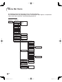
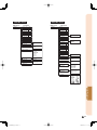
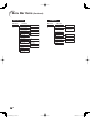
Menu Bar Items .............................................32
Using the Menu Screen .................................35
Menu Selections (Adjustments) ........................... 35
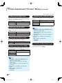
Picture Adjustment (“Picture” Menu) ..........37
Selecting the Picture Mode ................................. 37
Adjusting the Image ............................................ 37
Switching the Iris Setting ..................................... 38
Eco+Quiet ........................................................... 38
Using the Advanced ............................................ 38
Correcting Gradation of Video (Gamma Correction)
... 38
Adjusting the Colors ............................................ 38
Adjusting the Bright Boost ................................... 40
Selecting the Film Mode ...................................... 40
Setting Detail Enhancement ................................ 40
Reducing Image Noise (DNR) .............................. 40
Mosquito Noise Reduction (MNR) ....................... 40
Resetting All Adjustment Items ............................ 40
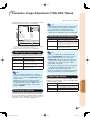
Computer Image Adjustment (“SIG-ADJ” Menu)
...41
Adjusting the Computer Image ............................ 41
Setting the Resolution ......................................... 41
Auto Sync (Auto Sync Adjustment) ...................... 41
Signal Type Setting .............................................. 41
Setting the Video System .................................... 42
Setting the Video Setup....................................... 42
Adjusting the Dynamic Range ............................. 42
Signal Info ........................................................... 42
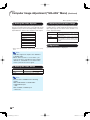
Adjusting the Projected Image (“SCR-ADJ” Menu)
...43
Setting the Resize Mode ..................................... 43
Adjusting the Image Position ............................... 43
Adjusting the Overscan ....................................... 43
Auto V-Keystone Correction ................................ 44
Keystone Mode Correction .................................. 44
Setting On-screen Display ................................... 45
Setting the Brightness of the Menu Screen .......... 45
Selecting the Background Image ......................... 45
Selecting the Menu Screen Position .................... 45
Reversing/Inverting Projected Images .................. 45
Selecting the On-screen Display Language ......... 45
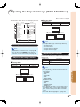
Adjusting the Projector Function (“PRJ-ADJ” Menu)
...46
Setting Auto Power Off Mode .............................. 46
Setting the Power Save Mode (Economy Mode)
... 46
Setting One Touch Play, System Standby
and Input Name ............................................ 46
Setting the Demo Mode
....................................... 47
Selecting the Transmission Speed (RS-232C) ...... 47
Fan Mode Setting ................................................ 47
Returning to the Default Settings ......................... 47
Lamp Timer (Life) ................................................ 47
Enjoying 3D Image Viewing……………….… 48
Precautions on using 3D Glasses ........................ 48
Precautions on viewing 3D images ...................... 48
Supplied Accessories for 3D Glasses .................. 50
Part Names ......................................................... 50
Before Using the 3D Glasses ............................... 51
Replacing the Button Cell Battery ........................ 51
Attaching the Nose Pad ...................................... 52
Attaching the 3D Glasses Band ........................... 52
Using the 3D Glasses .......................................... 52
Usage Range of the 3D Glasses .......................... 52
Viewing 3D Images ............................................. 53
3D Settings (“3D MENU”) .................................... 55
Setting the 3D Format Menu ............................... 56
Specifi cations – 3D Glasses ................................ 58

Introduction
-5
Reference
Appendix
Maintenance ..................................................59
Maintenance Indicators ................................60
Regarding the Lamp ......................................62
Lamp .................................................................. 62
Caution Concerning the Lamp............................. 62
Replacing the Lamp ............................................ 62
Removing and Installing the Lamp Unit ................ 63
Resetting the Lamp Timer ................................... 64
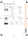
Connecting Pin Assignments .......................65
RS-232C Specifi cations and Commands ....66
Compatibility Chart .......................................70
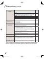
Troubleshooting .............................................72
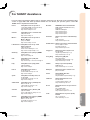
For SHARP Assistance ..................................75
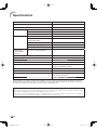
Specifi cations ................................................76
Dimensions ....................................................77
Index ...............................................................78
DLP
®
and the DLP logo are registered trade marks of Texas Instruments.
Microsoft
®
and Windows
®
are registered trade marks of Microsoft Corporation in the Unit ed States and/or other
countries.
PC/AT is a registered trademark of In ter na tion al Business Ma chines Cor po ra tion in the United States.
Macintosh
®
is a registered trademark of Apple Computer, Inc. in the United States and/or other countries.
HDMI, the HDMI logo and High-Defi nition Multimedia Interface are trademarks or reg is tered trademarks of
HDMI Licensing LLC.
All other company or product names are trademarks or registered trademarks of their re spec tive companies.
Some IC chips in this product include confi dential and/or trade secret property belonging to Texas Instru-
ments. Therefore you may not copy, modify, adapt, translate, distribute, reverse engineer, reverse assemble or
discompile the contents thereof.
•
•
•
•
•
•
•

-6
1. Read Instructions
All the safety and operating instructions should be read before
the product is operated.
2. Retain Instructions
The safety and operating instructions should be retained for
future reference.
3. Heed Warnings
All warnings on the product and in the operating instructions
should be adhered to.
4. Follow Instructions
All operating and use instructions should be followed.
5. Cleaning
Unplug this product from the wall outlet before cleaning. Do
not use liquid cleaners or aerosol cleaners. Use a damp cloth
for cleaning.
6. Attachments
Do not use attachments not recommended by the product
manufacturer as they may cause hazards.
7. Water and Moisture
Do not use this product near water–for example, near a bath
tub, wash bowl, kitchen sink, or laundry tub; in a wet basement;
or near a swimming pool; and the like.
8. Accessories
Do not place this product on an unstable cart, stand, tripod,
bracket, or table. The product may fall, causing serious injury
to a child or adult, and serious damage to the product. Use
only with a cart, stand, tripod, bracket, or table recommended
by the manufacturer, or sold with the product. Any mounting
of the product should follow the manufacturer’s instructions,
and should use a mounting accessory recom mended by the
manufacturer.
9. Transportation
A product and cart combination should
be moved with care. Quick stops, exces-
sive force, and uneven surfaces may
cause the product and cart combination
to overturn.
10. Ventilation
Slots and openings in the cabinet are provided for ventilation
to ensure reliable operation of the product and to protect it
from overheating, and these openings must not be blocked
or covered. The open ings should never be blocked by placing
the product on a bed, sofa, rug, or other similar surface. This
prod uct should not be placed in a built-in installation such as
a book case or rack unless proper ventilation is provided or the
manufacturer’s in struc tions have been adhered to.
11. Power Sources
This product should be operated only from the type of power
source indicated on the marking label. If you are not sure of
the type of power supply to your home, consult your product
dealer or local power com pany. For products intended to
operate from battery power, or other sources, refer to the
operating instructions.
12. Grounding or Polarization
This product is provided with one of the following types of plugs.
If the plug should fail to fi t into the power outlet,
please contact your electrician.
Do not defeat the safety purpose of the plug.
a. Two-wire type (mains) plug.
b. Three-wire grounding type (mains) plug with a
grounding terminal.
This plug will only fi t into a grounding type power
outlet.
IMPORTANT SAFEGUARDS
13. Power-Cord Protection
Power-supply cords should be routed so that they are not likely
to be walked on or pinched by items placed upon or against
them, paying particular attention to cords at plugs, convenience
receptacles, and the point where they exit from the product.
14. Lightning
For added protection for this product during a lightning storm, or
when it is left unattended and unused for long periods of time,
unplug it from the wall outlet and disconnect the cable system.
This will pre vent damage to the product due to lightning and
power-line surges.
15. Overloading
Do not overload wall outlets, extension cords, or integral
convenience receptacles as this can result in a risk of fi re or
electric shock.
16. Object and Liquid Entry
Never push objects of any kind into this product through
openings as they may touch dangerous voltage points or
short-out parts that could result in a fi re or electric shock. Never
spill liquid of any kind on the product.
17. Servicing
Do not attempt to service this product yourself as opening or
removing covers may expose you to dan ger ous voltage or other
hazards. Refer all servicing to qualifi ed service personnel.
18. Damage Requiring Service
Unplug this product from the wall outlet and refer servicing to
qualifi ed service person nel under the following conditions:
a. When the power-supply cord or plug is damaged.
b. If liquid has been spilled, or objects have fallen into the
product.
c. If the product has been exposed to rain or water.
d. If the product does not operate normally by following the
operating instructions. Adjust only those con trols that are
covered by the operating instructions, as an improper
adjustment of other controls may result in damage and
will often require extensive work by a qualifi ed technician
to restore the product to normal operation.
e. If the product has been dropped or damaged in any
way.
f. When the product exhibits a distinct change in
performance, this indicates a need for service.
19. Replacement Parts
When replacement parts are required, be sure the service
technician has used replace ment parts specified by the
manufacturer or have the same characteristics as the original
part. Unauthorized substitutions may result in fi re, electric shock,
or other hazards.
20. Safety Check
Upon completion of any service or repairs to this product, ask
the service technician to per form safety checks to determine
that the product is in proper operating condition.
21
.
Wall or Ceiling Mounting
This product should be mounted to a wall or ceiling only as
recommended by the manu facturer.
22. Heat
This product should be situated away from heat sources such
as radiators, heat registers, stoves, or other products (including
amplifi ers) that produce heat.
CAUTION: Please read all of these instructions before you operate this product and save these
instructions for later use.
Electrical energy can perform many useful functions. This product has been engineered and manufactured to as-
sure your personal safety. BUT IMPROPER USE CAN RESULT IN POTENTIAL ELECTRICAL SHOCK OR FIRE
HAZARDS. In order not to defeat the safeguards incorporated in this product, observe the following basic rules for
its installation, use and servicing.

Introduction
-7
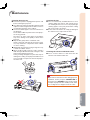
Caution concerning the lamp unit
Potential hazard of glass particles
if lamp ruptures. In case of lamp
rupture, contact your nearest Sharp
Authorized Projector Dealer or Service
Center for replacement.
See “Regarding the Lamp” on page
62.
Caution concerning the setup of the projector
For minimal servicing and to maintain high image quality,
SHARP recommends that this projector be installed in
an area free from humidity, dust and cigarette smoke.
When the projector is subjected to these environments,
the vents and lens must be cleaned more often. As
long as the projector is regularly cleaned, use in these
environments will not reduce the overall operation life of
the unit. Internal cleaning should only be performed by
a Sharp Authorized Projector Dealer or Service Center.
Do not set up the projector in places exposed to
direct sunlight or bright light.
Position the screen so that it is not in direct sunlight or
room light. Light falling directly on the screen washes out
the colors, making viewing diffi cult. Close the curtains
and dim the lights when setting up the screen in a sunny
or bright room.
Caution regarding placing of the projector
Place the projector on a level site within the adjustment
range (9 degrees) of the adjustment foot.
After the projector is purchased, a faint smell from the
vent may appear when the power is fi rst turned on. This
is normal and is not a malfunction. It will disappear after
the projector is used for a while.
When using the projector in high-altitude areas
such as mountains (at altitudes of approximate-
ly 4,900 feet (1,500 meters) or more)
When you use the projector in high-altitude areas with
thin air, set “Fan Mode” to “High”. Neglecting this can
affect the longevity of the optical system.
Use the projector at altitudes of 7,500 feet (2,300 meters)
or less.
Warning about placing the projector in a high
position
When placing the projector in a high position, make cer-
tain it is carefully secure to avoid personal injury caused
by the projector falling down.
Do not subject the projector to hard impact
and/or vibration.
Protect the lens so as not to hit or damage the surface
of the lens.
Rest your eyes occasionally.
Continuously watching the screen for long hours will
cause eye strain. Take regular breaks to rest your eyes.
Avoid locations with extremes of temperature.
The operating temperature of the projector is from 41°F
to 95°F (+5°C to +35°C).
The storage temperature of the projector is from –4°F
to 140°F (–20°C to +60°C).
Do not block the exhaust and intake vents.
Allow at least 11
13
/16 inches (30 cm) of space between
the exhaust vent and the nearest wall or obstruction.
Ensure that the intake vent and the exhaust vent are not
obstructed.
If the cooling fan becomes obstructed, a protection
circuit will automatically put the projector into standby
mode to prevent overheat damage. This does not indi-
cate a malfunction. (See page 60.) Remove the projector
power cord from the wall outlet and wait at least 10 min-
utes. Place the projector where the intake and exhaust
vents are not blocked, plug the power cord back in and
turn on the projector. This will return the projector to the
normal operating condition.
Caution regarding usage of the projector
If you are not to use the projector for a long time or
before moving the projector, make certain you unplug
the power cord from the wall outlet, and disconnect any
other cables connected to it.
Do not carry the projector by holding the lens.
When storing the projector, ensure that you close the
lens shutter.
Do not expose the projector to direct sunlight or place
next to heat sources. Doing so may affect the cabinet
color or cause deformation of the plastic cover.
Observe the following safeguards when setting up your projector.

-8
Other connected equipment
When connecting a computer or other audio-visual
equipment to the projector, make the connections
AFTER unplugging the power cord of the projector
from the AC outlet and turning off the equipment to be
connected.
Please read the operation manuals of the projector and
the equipment to be connected for instructions on how
to make the connections.
Using the projector in other countries
The power supply voltage and the shape of the plug may
vary depending on the region or country you are using the
projector in. When using the projector overseas, make
sure you use an appropriate power cord for the country
you are in.
Temperature monitor function
If the temperature inside the projector increases, due
to blockage of the air vents, or the setting location,
the temperature warning indicator will blink. And if the
temperature keeps on rising, “ ” will illuminate in
the lower left corner of the picture with the temperature
warning indicator blinking. If this state continues, the
lamp will turn off, the cooling fan will run and then the
projector will enter standby mode. Refer to “Maintenance
Indicators” on pages 60 and 61 for details.
Info
• The cooling fan regulates the internal temperature,
and its performance is automatically controlled.
The sound of the fan may change during projector
operation due to changes in the fan speed. This
does not indicate malfunction.
Prevention of accidental ingestion
Keep the batteries and band accessory out of the
reach of small children. Small children can accidentally
swallow these parts.
– If a child accidentally swallows any of these parts,
seek immediate medical attention.
Do not disassemble
Do not disassemble or modify the 3D Glasses.
Caution for lithium battery
Batteries must not be exposed to excessive heat such
as direct sunlight or fi re.
Replace only with the same or equivalent type of battery.
The battery may explode if improperly replaced.
Take care not to reverse the battery poles (+ and –)
when loading the battery. Follow the correct procedure
when loading the battery. (See page 51.) Loading the
battery incorrectly may damage the battery or cause it
to leak battery fl uid, which could result in a fi re, injury or
damage.
Handling the 3D Glasses
Do not drop, exert pressure on, or step on the 3D
Glasses. Doing so may damage the glass section, which
may result in injury.
Be careful not to trap your fi nger in the hinge section of
the 3D Glasses. Doing so may result in injury.
– Pay special attention when children are using this
product.
Using the 3D Glasses
Parents/guardians should monitor children’s view-
ing habits to avoid their prolonged use without rest
periods.
Use only the 3D Glasses recommended for this product.
Use the 3D Glasses only for the specifi ed purpose.
Do not move around while wearing the 3D Glasses. The
surrounding area appears dark, which may result in
falling or other accidents that may cause injury.
Caring for the 3D Glasses
Use only the cloth provided with the 3D Glasses to clean
the lenses. Remove dust and soil from the cloth. Any
dust or other soiling on the cloth may result in scratches
on the product. Do not use solvents such as benzene
or thinners as doing so may cause the coating to peel
off.
When cleaning the 3D Glasses, take care not to allow
water or other fl uids to come into contact with the
glasses.
Always store the 3D Glasses in the case provided when
not in use.
When storing the 3D Glasses, avoid very humid or hot
locations.
Viewing 3D images
If you experience dizziness, nausea, or other discomfort
while viewing 3D images, discontinue use and rest your
eyes.
Do not use the 3D Glasses if they are cracked or bro-
ken.
Observe the following safeguards when using the 3D Glasses.

Introduction
-9
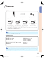
Accessories
Supplied accessories
Lamp unit AN-K15LP
Ceiling-mount adaptor AN-60KT
Ceiling-mount bracket AN-XRCM30 (for U.S.A. only)
Ceiling-mount unit AN-TK201 <for AN-60KT>
AN-TK202 <for AN-60KT>
Ceiling-mount extension tube AN-EP101B <for AN-XRCM30>
(for U.S.A. only)
3 RCA to mini D-sub 15 pin cable (10' (3.0 m)) AN-C3CP2
3D Glasses AN-3DG10-S
AN-3DG10-R
AN-3DG10-A
Two AA size batteries
<UBATUA020WJZZ>
Remote control
<RRMCGA929WJSA>
Note
• Some of the optional accessories may not be available depending on the region. Please check with your
nearest Sharp Authorized Projector Dealer or Service Center.
Note
• Codes in “< >” are Replacement parts codes.
Optional accessories
Power cord
*2
For U.S. and
Canada, etc.
(6' (1.8 m))
<QACCDA007WJPZ>
(1)
*1 See pages 50 to 52 for details of the 3D Glasses and their accessories.
*2 Which power cords are supplied along with your projector depends on the region. Use the power cord that
corresponds to the wall outlet in your country.
• Operation manual <TINS-E929WJZZ>
(2)
For Europe,
except U.K.
(6' (1.8 m))
<QACCVA011WJPZ>
(3)
For U.K. and
Singapore
(6' (1.8 m))
<QACCBA036WJPZ>
(4)
For Australia,
New Zealand and Oceania
(6' (1.8 m))
<QACCLA018WJPZ>
Two pairs of 3D Glasses
*1
<KOPTLA002WJN1>

-10
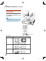
Numbers in refer to the main pages in this operation manual where the topic is explained.
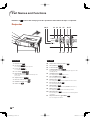
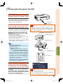
Projector
Part Names and Functions
Front View
1 Exhaust vent
59
2 Zoom ring
15, 24
For enlarging/reducing the picture.
3 Focus ring
15, 24
For adjusting the focus.
4 Lens shutter
23, 28, 63
5 IR (infrared) emitter
52
Emits an infrared signal when 3D image s are
projected.
6 Adjustment foot
15, 24
7 Remote control sensor
13
8 HEIGHT ADJUST lever
24
9 Intake vent
59
Top View
10 Temperature warning indicator
60
11 Lamp indicator
23, 60
12 Power indicator
23, 60
13 STANDBY/ON button
14, 23
For turning the power on and putting the projector into
standby mode.
14 3D MENU button
53
For displaying the 3D MENU screen.
15 PICTURE MODE button
28
For selecting the appropriate picture.
16 ENTER button
35
For setting items selected or adjusted on the menu.
17 INPUT buttons (P/R)
27
For switching input mode.
18 RESIZE button
30
For switching the picture size (NORMAL, 16:9, etc.).
19 MENU button
35
For displaying adjustment and setting screens.
20 RETURN button
35
For returning to the previous menu screen during menu
operations.
21 Adjustment buttons (P/R/O/Q)
35
For selecting menu items.
2
4
5
6
3
8 9
1
7
121110 13 14
18
19 20 21
15 1716

Introduction
-11
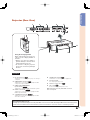
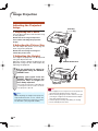
Projector (Rear View)
Using the Kensington Lock
This projector has a Kensington Security Standard connector for use with a Kensington MicroSaver Security System.
Refer to the information that came with the system for instructions on how to use it to secure the projector.
•
Terminals
11
79 108
123 5
4
6
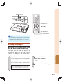
Using the Carrying Handle
When transporting the projector,
carry it by the carrying handle on
the side.
Always close the lens shutter to
prevent damage to the lens when
transporting the projector.
Do not lift or carry the projector
by the lens as this may damage
the lens.
•
•
1 RS-232C terminal
22
Terminal for controlling the projector using a
computer.
2 COMPONENT terminals
19
Terminal for connecting video equipment with
component output terminal.
3 COMPUTER/COMPONENT
input terminal
19, 21
Terminal for computer RGB and YPbPr signals.
4 HDMI1, 2 terminals
19, 20
Terminal for connecting video equipment with
HDMI output terminal.
5 S-VIDEO input terminal
19, 20
Terminal for connecting video equipment with
an S-video terminal.
6 VIDEO input terminal
19
Terminal for connecting video equipment.
7 Carrying handle
For carrying the projector.
8 Remote control sensor
13
9 AC socket
23
Connect the supplied power cord.
10 Kensington Security Standard connector
11 Security bar

-12
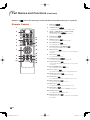
Numbers in refer to the main pages in this operation manual where the topic is explained.
Remote Control
2
3
4
7
9
6
1
8
10
20
11
12
5 13
14
15
17
18
19
16
1 ON button
14, 23
For turning the power on.
2 STANDBY button
15, 23
For putting the projector into the standby mode.
3 HDMI1, 2, COMPONENT, S-VIDEO, VIDEO,
COMPUTER buttons
15, 27
For switching to the respective input modes.
4 FREEZE button
28
For freezing images.
5 MAGNIFY buttons
29
For enlarging/reducing part of the image.
6 KEYSTONE button
25
For entering the Keystone mode.
7 Adjustment buttons (P/R/O/Q)
35
For selecting and adjusting menu items.
8 RETURN button
35
For returning to the previous me nu scre en during menu
operations.
9 INPUT button
27
For switching input mode.
10 3D ON/OFF button
53, 54
For switching between 2D and 3D modes.
11 AUTO SYNC button
28
For automatically adjusting images when connected to
a computer.
12 PICTURE MODE button
28
For selecting the appropriate picture.
13 IRIS 1, 2 buttons
29
For switching “High Brightness” and “High Contrast”.
14 IMAGE SH IFT but ton
27
For shifting images horizontally and vertically.
15 ENTER button
35
For setting items selected or adjusted on the menu.
16 MENU HIDE button
29
For temporarily hiding menu screen.
17 MENU button
35
For displaying adjustment and setting screens.
18 RESIZE button
30
For switching the picture size (NORMAL, 16:9, etc.).
19 3D MENU button
53
For displaying the 3D MENU screen.
20 ECO+QUIET button
29
For lowering the noise of the cooling fan and extending
the lamp life.
Part Names and Functions (Continued)

Introduction
-13
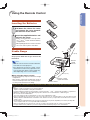
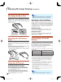
Using the Remote Control
Inserting the Batteries
1
Pull down the tab on the cover
and remove the cover towards
the direction of the arrow.
2
Insert the supplied batteries and
put back the cover.
• Make sure the polarities correctly match
the
m and n marks inside the battery
compartment.
• When putting back the cover, be sure that
the cover clicks in place and settles.
Usable Range
The remote control can be used to control
the projector within the ranges shown in the
illustration.
Note
• Remote control sensor is located on both the
front and rear of the projector.
• The signal from the remote control can be
refl ected off a screen for easy operation. How-
ever, the effective distance of the signal may
differ depending on the screen material.
When using the remote control:
• Be sure not to drop, expose to moisture or high
temperature.
• The remote control may malfunction under a
fl uorescent lamp. In this case, move the projec-
tor away from the fl uorescent lamp.
1
2
Remote
control
sensors
30°
30°
23' (7 m)
Remote control
signal transmitter
Remote control
23' (7 m)
30°
30°
Incorrect use of the batteries may cause them to leak or explode. Please follow the precautions below
Caution
Danger of explosion if battery is incorrectly replaced.
Replace only with alkaline or manganese batteries.
Insert the batteries making sure the polarities correctly match the
m
and
n
marks inside the battery compartment.
Batteries of different types have different properties, therefore do not mix batteries of different types.
Do not mix new and old batteries.
This may shorten the life of new batteries or may cause old batteries to leak.
Remove the batteries from the remote control once they have run out, as leaving them in can cause them to leak.
Battery fl uid from leaked batteries is harmful to skin, therefore ensure you wipe them fi rst and then remove them
using a cloth.
The batteries included with this projector may run down in a short period, depending on how they are kept. Be
sure to replace them as soon as possible with new batteries.
Remove the batteries from the remote control if you will not be using the remote control for a long time.
Comply with the rules (ordinance) of each local government when disposing of worn-out batteries.
•
•
•
•
•
•
•
•

-14
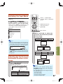
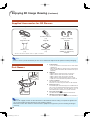
Quick Start
This section provides an example showing how to connect the projector to video equipment that has an HDMI
output terminal with a brief explanation of the steps from connection through to image projection.
For details, see the pages suggested in each step.
1. Place the projector facing a screen
Page 16
2.
Connect the projector to the video equipment and plug
the power cord into the AC socket of the projector
Pages 19-23
3.
Open the lens shutter fully and then turn the projector on
Page 23
Press STANDBY/ON on the projector or ON on the
remote control pointing the remote control towards
the projector.
6 Adjustment feet
6 Focus ring
6 Zoom ring
7 STANDBY button
3 ON button
5 Input Mode
Select buttons
3, 7 STANDBY/ON
button
5 INPUT button
1
2
STANDBY/ON button
On the projector
2
ON button
On the remote control

Quick Start
-15
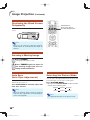
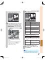
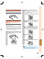
4. Turn the video equipment on and start playback
5. Select the input mode
Page 27
Press HDMI1 on the remote control to select “HDMI1” for the Input mode.
• Press HDMI1, HDMI2, COMPONENT, S-VIDEO, VIDEO and COMPUTER on the remote control to
switch the Input mode.
• Press P or R to select your desired input mode when you press INPUT on the remote control or on the
projector.
6. Adjust the projector angle, focus and zoom
Page 24
1. The focus is adjusted by
rotating the focus ring.
2. Zooming is adjusted by
rotating the zoom ring.
3. The projector angle is
adjusted by using the
adjustment feet.
Focus ring Zoom ring
Adjustment feet
7. Turn the power off
Page 23
Press STANDBY/ON on the projector or STANDBY on the remote control, then press that button again
while the confi rmation message is displayed, to put the projector into standby mode.
HDMI1 button
Playback
On-screen display
• When the image is distorted
trapezoidally, the keystone
correction is needed.
(See page 25.)
1
STANDBY
button
On the remote control
HDMI1
YPbPr
1080P
On the projector
2
1
STANDBY/ON button

-16
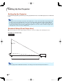
Setting Up the Projector
Setting Up the Projector
For optimal image quality, position the projector perpendicular to the screen with the projector’s feet fl at and
level.
Note
• The projector lens should be centered in the middle of the screen. If the horizontal line passing through
the lens center is not perpendicular to the screen, the image will be distorted, making viewing diffi cult.
• For optimal image, position the screen so that it is not in direct sunlight or room light. Light falling directly
on the screen washes out the colors, making viewing diffi cult. Close the curtains and dim the lights when
setting up the screen in a sunny or bright room.
Standard Setup (Front Projection)
Place the projector at the required distance from the screen according to the desired picture size.
Example of standard setup
Side View
Note
• Refer to page 18 for additional information concerning “Screen Size and Projection Distance”.
H
L
90°
Screen
Lens center

Setup
-17
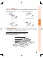
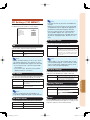
Projection (PRJ) Mode
The projector can use any of the 4 projection modes, shown in the diagram below. Select the mode most ap-
propriate for the projection setting in use. (You can set the PRJ Mode in “SCR-ADJ” menu. See page 45.)
Table mounted, front projection
Ceiling mounted, front projection
Menu item “Front”
Table mounted, rear projection
(with a translucent screen)
Menu item “Rear”
Menu item “Ceiling + Front”
Ceiling mounted, rear projection
(with a translucent screen)
For details, refer to “Screen Size and Projection Distance” on page 18.
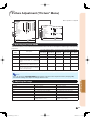
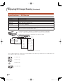
Example : When using a wide screen (16:9)
Indication of the Projection Image Size and Projection Distance
4'1" ~ 4'9"
(1.3 m ~ 1.4 m)
8'3" ~ 9'6"
(2.5 m ~ 2.9 m)
10'4" ~ 11'11"
(3.1 m ~ 3.6 m)
20'7" ~ 23'9"
(6.3 m ~ 7.2 m)
51'6"
(15.7 m)
500" (1270 cm)
200" (508 cm)
100" (254 cm)
80" (203 cm)
40" (102 cm)
35"×20"
(89 c
m × 50 cm)
70"×39"
(177 cm × 100 cm)
87"×49"
(221 cm × 125 cm)
174"×98"
(443 cm
×
249 cm)
436
"
×245
"
(1107 cm
×
623
cm )
Picture Size
Projection
Distance
Ceiling-mount Setup
It is recommended that you use the optional Sharp ceiling-mount adaptor and unit for this installation. Before
mounting the projector, contact your nearest Sharp Authorized Projector Dealer or Service Center to obtain
the recommended ceiling-mount adaptor and unit (sold separately).
Menu item “Ceiling + Rear”

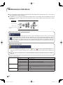
-18
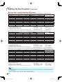
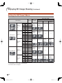
Screen Size and Projection Distance
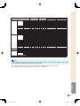
When using a wide screen (16:9): In case of displaying the 16:9 picture on the whole of the 16:9 screen.
x : Picture (Screen) diagonal size: 40" – 500"
L : Projection distance (ft/m)
L1 : Minimum projection distance (ft/m)
L2 : Maximum projection distance (ft/m)
H : Distance from the lens center to the bottom of the image (in/cm)
Note
• Refer to page 16 concerning “Projection distance [L]” and “Distance from the lens center to the bottom of
the image [H]”.
• Allow a margin of error in the value in the diagrams above.
The formula for picture size and projection distance
Picture (Screen) size Projection distance [L]
Distance from the lens center to
the bottom of the image [H]
Diag. (x) Width Height Minimum [L1] Maximum [L2]
500" (1270 cm) 436" (1107 cm) 245" (623 cm) 51'6" (15.7 m)
—
39
3
/
8
" (100 cm)
400" (1016 cm) 349" (886 cm) 196" (498 cm) 41'2" (12.6 m) 47'6" (14.5 m) 31
1
/
2
" (80 cm)
300" (762 cm) 261" (664 cm) 147" (374 cm) 30'11" (9.4 m) 35'8" (10.9 m) 23
5
/
8
" (60 cm)
250" (635 cm) 218" (553 cm) 123" (311 cm) 25'9" (7.9 m) 29'8" (9.1 m) 19
11
/
16
" (50 cm)
200" (508 cm) 174" (443 cm) 98" (249 cm) 20'7" (6.3 m) 23'9" (7.2 m) 15
3
/
4
" (40 cm)
150" (381 cm) 131" (332 cm) 74" (187 cm) 15'5" (4.7 m) 17'10" (5.4 m) 11
13
/
16
" (30 cm)
120" (305 cm) 105" (266 cm) 59" (149 cm) 12'4" (3.8 m) 14'3" (4.3 m) 9
29
/
64
" (24 cm)
100" (254 cm) 87" (221 cm) 49" (125 cm) 10'4" (3.1 m) 11'11" (3.6 m) 7
7
/
8
" (20 cm)
80" (203 cm) 70" (177 cm) 39" (100 cm) 8'3" (2.5 m) 9'6" (2.9 m) 6
19
/
64
" (16 cm)
60" (152 cm) 52" (133 cm) 29" (75 cm) 6'2" (1.9 m) 7'2" (2.2 m) 4
23
/
32
" (12 cm)
40" (102 cm) 35" (89 cm) 20" (50 cm) 4'1" (1.3 m) 4'9" (1.4 m) 3
5
/
32
" (8 cm)
[Feet/inches]
L1 (ft) = 0.0314 x / 0.3048
L2 (ft) = 0.0362 x / 0.3048
H (in) = 0.2 x / 2.54
[m/cm]
L1 (m) = 0.0314 x
L2 (m) = 0.0362 x
H (cm) = 0.2 x
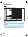
When using a normal screen (4:3): In case of displaying the 4:3 picture on the whole of the 4:3 screen.
x : Picture (Screen) diagonal size: 40" – 400"
L : Projection distance (ft/m)
L1 : Minimum projection distance (ft/m)
L2 : Maximum projection distance (ft/m)
H : Distance from the lens center to the bottom of the image (in/cm)
The formula for picture size and projection distance
Picture (Screen) size Projection distance [L]
Distance from the lens center to
the bottom of the image [H]
Diag. (x) Width Height Minimum [L1] Maximum [L2]
400" (1016 cm) 320" (813 cm) 240" (610 cm) 50'5" (15.4 m)
—
38
35
/
64
" (98 cm)
300" (762 cm) 240" (610 cm) 180" (457 cm) 37'10" (11.5 m) 43'7" (13.3 m) 28
29
/
32
" (73 cm)
250" (635 cm) 200" (508 cm) 150" (381 cm) 31'6" (9.6 m) 36'4" (11.1 m) 24
3
/
32
" (61 cm)
200" (508 cm) 160" (406 cm) 120" (305 cm) 25'3" (7.7 m) 29'1" (8.9 m) 19
17
/
64
" (49 cm)
150" (381 cm) 120" (305 cm) 90" (229 cm) 18'11" (5.8 m) 21'10" (6.6 m) 14
29
/
64
" (37 cm)
120" (305 cm) 96" (244 cm) 72" (183 cm) 15'2" (4.6 m) 17'5" (5.3 m) 11
9
/
16
" (29 cm)
100" (254 cm) 80" (203 cm) 60" (152 cm) 12'7" (3.8 m) 14'6" (4.4 m) 9
41
/
64
" (24 cm)
80" (203 cm) 64" (163 cm) 48" (122 cm) 10'1" (3.1 m) 11'8" (3.5 m) 7
45
/
64
" (20 cm)
70" (178 cm) 56" (142 cm) 42" (107 cm) 8'10" (2.7 m) 10'2" (3.1 m) 6
3
/
4
" (17 cm)
60" (152 cm) 48" (122 cm) 36" (91 cm) 7'7" (2.3 m) 8'9" (2.7 m) 5
25
/
32
" (15 cm)
40" (102 cm) 32" (81 cm) 24" (61 cm) 5'1" (1.5 m) 5'10" (1.8 m) 3
55
/
64
" (10 cm)
[Feet/inches]
L1 (ft) = 0.03843 x / 0.3048
L2 (ft) = 0.0443 x / 0.3048
H (in) = 0.24477 x / 2.54
[m/cm]
L1 (m) = 0.03843 x
L2 (m) = 0.0443 x
H (cm) = 0.24477 x
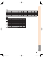
When using a normal screen (4:3): In case of setting the 16:9 picture to the full horizontal width of the 4:3 screen.
x : Screen diagonal size: 40" – 500"
L : Projection distance (ft/m)
L1 : Minimum projection distance (ft/m)
L2 : Maximum projection distance (ft/m)
H : Distance from the lens center to the bottom of the image (in/cm)
The formula for screen size and projection distance
Screen size Projection distance [L]
Distance from the lens center to
the bottom of the image [H]
Diag. (x) Width Height Minimum [L1] Maximum [L2]
500" (1270 cm) 400" (1016 cm) 300" (762 cm) 47'3" (14.4 m)
—
36
9
/
64
" (92 cm)
400" (1016 cm) 320" (813 cm) 240" (610 cm) 37'10" (11.5 m) 43'7" (13.3 m) 28
29
/
32
" (73 cm)
300" (762 cm) 240" (610 cm) 180" (457 cm) 28'4" (8.6 m) 32'8" (10.0 m) 21
11
/
16
" (55 cm)
250" (635 cm) 200" (508 cm) 150" (381 cm) 23'8" (7.2 m) 27'3" (8.3 m) 18
1
/
16
" (46 cm)
200" (508 cm) 160" (406 cm) 120" (305 cm) 18'11" (5.8 m) 21'10" (6.6 m) 14
29
/
64
" (37 cm)
150" (381 cm) 120" (305 cm) 90" (229 cm) 14'2" (4.3 m) 16'4" (5.0 m) 10
27
/
32
" (28 cm)
120" (305 cm) 96" (244 cm) 72" (183 cm) 11'4" (3.5 m) 13'1" (4.0 m) 8
43
/
64
" (22 cm)
100" (254 cm) 80" (203 cm) 60" (152 cm) 9'5" (2.9 m) 10'11" (3.3 m) 7
15
/
64
" (18 cm)
80" (203 cm) 64" (163 cm) 48" (122 cm) 7'7" (2.3 m) 8'9" (2.7 m) 5
25
/
32
" (15 cm)
70" (178 cm) 56" (142 cm) 42" (107 cm) 6'7" (2.0 m) 7'8" (2.3 m) 5
1
/
16
" (13 cm)
60" (152 cm) 48" (122 cm) 36" (91 cm) 5'8" (1.7 m) 6'6" (2.0 m) 4
11
/
32
" (11 cm)
40" (102 cm) 32" (81 cm) 24" (61 cm) 3'9" (1.2 m) 4'4" (1.3 m) 2
57
/
64
" (7 cm)
[Feet/inches]
L1 (ft) = 0.02882 x / 0.3048
L2 (ft) = 0.03323 x / 0.3048
H (in) = 0.18358 x / 2.54
[m/cm]
L1 (m) = 0.02882 x
L2 (m) = 0.03323 x
H (cm) = 0.18358 x
Setting Up the Projector (Continued)
Page is loading ...
Page is loading ...
Page is loading ...
Page is loading ...
Page is loading ...
Page is loading ...
Page is loading ...
Page is loading ...
Page is loading ...
Page is loading ...
Page is loading ...
Page is loading ...
Page is loading ...
Page is loading ...
Page is loading ...
Page is loading ...
Page is loading ...
Page is loading ...
Page is loading ...
Page is loading ...
Page is loading ...
Page is loading ...
Page is loading ...
Page is loading ...
Page is loading ...
Page is loading ...
Page is loading ...
Page is loading ...
Page is loading ...
Page is loading ...
Page is loading ...
Page is loading ...
Page is loading ...
Page is loading ...
Page is loading ...
Page is loading ...
Page is loading ...
Page is loading ...
Page is loading ...
Page is loading ...
Page is loading ...
Page is loading ...
Page is loading ...
Page is loading ...
Page is loading ...
Page is loading ...
Page is loading ...
Page is loading ...
Page is loading ...
Page is loading ...
Page is loading ...
Page is loading ...
Page is loading ...
Page is loading ...
Page is loading ...
Page is loading ...
Page is loading ...
Page is loading ...
Page is loading ...
Page is loading ...
Page is loading ...
Page is loading ...
-
 1
1
-
 2
2
-
 3
3
-
 4
4
-
 5
5
-
 6
6
-
 7
7
-
 8
8
-
 9
9
-
 10
10
-
 11
11
-
 12
12
-
 13
13
-
 14
14
-
 15
15
-
 16
16
-
 17
17
-
 18
18
-
 19
19
-
 20
20
-
 21
21
-
 22
22
-
 23
23
-
 24
24
-
 25
25
-
 26
26
-
 27
27
-
 28
28
-
 29
29
-
 30
30
-
 31
31
-
 32
32
-
 33
33
-
 34
34
-
 35
35
-
 36
36
-
 37
37
-
 38
38
-
 39
39
-
 40
40
-
 41
41
-
 42
42
-
 43
43
-
 44
44
-
 45
45
-
 46
46
-
 47
47
-
 48
48
-
 49
49
-
 50
50
-
 51
51
-
 52
52
-
 53
53
-
 54
54
-
 55
55
-
 56
56
-
 57
57
-
 58
58
-
 59
59
-
 60
60
-
 61
61
-
 62
62
-
 63
63
-
 64
64
-
 65
65
-
 66
66
-
 67
67
-
 68
68
-
 69
69
-
 70
70
-
 71
71
-
 72
72
-
 73
73
-
 74
74
-
 75
75
-
 76
76
-
 77
77
-
 78
78
-
 79
79
-
 80
80
-
 81
81
-
 82
82


Sharp XV-Z17000 Owner's manual
- Category
- Data projectors
- Type
- Owner's manual
Ask a question and I''ll find the answer in the document
Finding information in a document is now easier with AI
Related papers
-
Sharp XV-Z17000 User manual
-
Sharp Projector DT-100 User manual
-
-
-
-
Sharp PG-D4010X User manual
-
-
-
Sharp Notevision PG-D3050W User manual
-