Page is loading ...

Nest Learning Thermostat
Pro Installation & Configuration Guide
Last updated: November 2017
Version: 1.1

Table of Contents
General Information 2
Nest Learning Thermostat Installation Features 2
HVAC System Compatibility 3
Technical Specifications 3
How to use Pro Setup 4
Installation Overview 5
Supported Wiring 7
Nest Thermostat Connectors 7
Wiring Diagrams: Conventional Heating/Cooling Systems 8
Wiring Diagrams: Heat Pump Systems 12
Wiring Diagrams: Multi-Speed Fans 17
Wiring Diagrams: Humidifiers and Dehumidifiers 18
Configuring Nest Thermostat with Pro Setup 19
How to use Pro Setup 19
How to Configure Complex Systems 20
Troubleshooting 23
Handling Unusual Thermostat Wiring 23
Reference Materials 26
How To Quick Reference Guide 26
Wiring Error Quick Reference Guide 29
Troubleshooting Quick Reference Guide 32
Humidifier/Dehumidifier Configurations 34
Where to Find Additional Help 36
1

General Information
Nest Learning Thermostat Installation Features
No jumper wires needed
The Nest Thermostat does not use jumper wires, it will automatically jump terminals for you. Do not connect
jumper wires to the Nest Thermostat. Before removing any wires from the old thermostat, including jumper
wires, take a picture of the existing wiring configuration in case you or the homeowner need to reinstall it.
System Match
When you first install the Nest Thermostat, it checks to see what wires you’ve inserted into the base’s
connectors and prompts you for additional information where needed.
Pro Setup
Pro Setup lets Nest Pros configure advanced settings in order to set up complex systems, including dual-fuel
systems, humidifiers/dehumidifiers and multi-speed fans. Pro Setup also activates a customer’s extended
warranty if the Nest Thermostat is purchased from and installed by a Pro.
Silent relays
Nest Thermostats use solid state switching instead of relays so there’s no noise when it switches on or off.
You will not hear any “clicking” during system testing and activation.
Press connectors
Connecting the HVAC system wiring to the Nest Thermostat base is easy using the press connectors. Simply
insert the wire into the connector as far as it will go until the press connector stays in the down position.
Multifunctional Star connector
The Star connector on the Nest Thermostat can control a number of different applications. If you insert a wire
into this terminal, the Nest Thermostat will ask you to select the application and will control it based on your
selection. For a list of compatible applications that can be inserted into the Star connector, see the wiring
diagrams below.
2

HVAC System Compatibility
System Compatibility:
● Works with 95% of 24V systems: gas,
electric, oil, forced air, heat pump & radiant
● Heating: 1, 2 and 3 stages (W1, W2, W3)
● Cooling: 1 and 2 stages (Y1, Y2)
● Power (C, Rh, Rc)
● Fan (including multi-speed) (G or G1,G2,G3)
● Humidifier or dehumidifier (HUM, DEHUM)
● Heat pump: with auxiliary/alternate and emergency
heat (O/B, AUX, ALT, E)
Connectors:
Networking requirements:
● Y1
● Y2
● G
● O/B
● Rc
● W1
● W2/AUX
● C
●
● Rh
● Wi-Fi is required for software updates and remote
control with the Nest App
● Wi-Fi 802.11 b/g/n, 2.4 GHz
● Secure: AES-128, SSL/TLS, WEP, WPA/WPA2
Technical Specifications
Power:
- No external power required
- No common wire required with
most installations
- Built in lithium-ion battery
- Uses less than 1 kWh/month
- Voltage requirement: 20-30V AC
Display:
- 24-bit color LCD
- 480x480 resolution at 229 pixels
per inch (PPI)
- 5.3 cm (2.08 in) diameter
Sensors:
- Temperature (10 sensors) +/-
.5°F Humidity +/- 3%RH
- Near-field activity
- Far-field activity
- Ambient light
- Nest utilizes local weather data
over Wi-Fi instead of outdoor
temperature sensors
Green:
- Energy Star
- CEC Title 20
- CEC Title 24 Residential
- CEC Title 24 Nonresidential
- Recyclable packaging
Box contents:
- Display
- Base
- Trim kit
- Mounting screws
- Wire labels
- Installation guide
- Welcome guide
Size and weight:
Display:
- Mass = 205.4 g / 7.25 oz
- Diameter = 8.4 cm / 3.30”
- Height = 2.69 / 1.06”
Base:
- Mass = 38.3 g / 1.35 oz
- Diameter = 7.6 cm / 3”
- Height = 1.1 cm / 0.42”
3

How to use Pro Setup
When going through setup on the Nest Thermostat, the first question in the Equipment section asks if you’re a
Homeowner or Pro. Selecting Pro will take you through Pro Setup, which has additional options to help
professional installers setup more complex systems. In Pro Setup, you can configure advanced settings such
as alternate and primary heating sources, lockout temperatures, fan activation and more. Pro Setup is required
to set up dual-fuel systems as well as whole-home humidifiers and dehumidifiers.
How to give your customer an extended Pro Warranty
Customers who purchase a Nest Thermostat from a Nest Pro and have it installed can get an extended Pro
Warranty. The Pro Warranty adds an additional 3 years of coverage for a total of 5 years. Entering your Pro ID
in Pro Setup will automatically activate your customer’s extended warranty as long as all of the following are
true:
● You must sell and install the thermostat for your customer
● You must enter your Pro ID during the setup installation
● The thermostat must be connected to Wi-Fi and added to the customer’s Nest Account
If all of the above are completed your customer will get the extended warranty automatically.
4

Installation Overview
1. Confirm system compatibility
Before opening the Nest Thermostat package, check all of the wires connected to the current thermostat
against the list of available connectors on the Nest Thermostat box, or use the Compatibility Checker at
http://nest.com/works to show you exactly where to connect each wire.
2. Briefly test the HVAC system
Test the heating, cooling, fan and other system features with the current thermostat before installing the
Nest thermostat so you can address any existing issues.
At times, outdoor weather conditions may prohibit testing of heating or cooling. In those cases, inform
the customer that you cannot test and ask the customer about the system's operation and performance.
3. Turn off power to the HVAC system
Turn off the power to the system to protect yourself and the equipment. Locate the circuit box and check
to see if the circuits are labeled or if there is a circuit directory. Turn off all HVAC system circuits.
If you cannot determine which circuits belong to the HVAC system turn off the main circuit breaker after
obtaining permission from your customer. Confirm the power is off by attempting to activate the HVAC
system using the existing thermostat.
4. Remove the old thermostat
Before removing the old thermostat, take a quick picture of the wiring with your phone in case you need
it for reference. Disconnect the wiring and remove the old thermostat. Use the wire labels included in
Nest Thermostat Installation Guide if needed. Be sure to leave the original thermostat, hardware and any
jumper wires with the customer.
5. Offer the customer installation finishing options
You may need to cover up holes, old paint or marks left by the old thermostat. Ask your customer if they
prefer to repair the wall themselves or if they want to have the Nest trim plate installed. Let the customer
know that the trim plate can be painted to match the wall.
6. Install the Nest Thermostat
Run the wires through the center of the Nest Thermostat base and attach it to the wall using the screws
provided. Do not use a power drill on the screws. Over tightening the screws can damage the circuitry in
the Nest base. For paneling, plaster-and-lath, or if there is a stud behind the thermostat, pre-drill a hole
using a 3/32” bit first.
Use the built-in level for proper alignment. Trim or re-strip any wires as necessary and connect them to
their corresponding terminals on the base. Make sure the wire is straight and the connector button
stays down after inserting it.
5

7. Walk through the Setup Interview with your customer
Most of the Pro Setup questions are easy for a professional to answer, but your customer should
answer some of the questions like prefered temperatures and Wi-Fi passwords.
8. Allow the Nest Thermostat to update
If there’s a necessary software update, the Nest Thermostat will start downloading it as soon as it
connects to the internet. The update can take several minutes depending on the speed of the internet
connection, so take advantage of this time to explain some of Nest Thermostat’s key features to your
customer.
9. Test heating and cooling
This is vital to any installation in order to prevent a callback. After setting up the Nest Thermostat, run
each part of the system for a few minutes. This will ensure that the Nest Thermostat is installed
correctly and there aren’t any HVAC compatibility issues. See page 26 for additional details on
performing post-installation testing.
10. Help your customer pair the Nest Thermostat with the Nest App
If your customer already has a Nest product and is using the Nest App, show them how to add the
thermostat to their Nest account. If it’s your customer’s first Nest product, show them how to download
the Nest App, create an account and then add the Nest Thermostat.
6

Supported Wiring
Nest Thermostat Connectors
Conventional connectors:
Heat pump connectors:
Y1
Stage 1 compressor relay
Y1
Stage 1 compressor relay
Y2
Stage 2 compressor relay, 2nd-speed fan
relay
Y2
Stage 2 compressor relay
G
Fan relay
G
Fan relay
O/B
Not used
O/B
Changeover valve relay
Rc
24VAC power from cooling transformer*
Rc
Not used
W1
Stage 1 heat relay
W1
Stage 1 heat relay
W2/AUX
Stage 2 heat relay
W2/AUX
Auxiliary heat relay
C
24VAC common wire
C
24VAC common wire.
Star *
Stage 3 heat (W3), humidification (HUM), or
dehumidification (DEHUM), 3rd-speed fan
relay
Star *
Emergency heat (E), humidification (HUM), or
dehumidification (DEHUM)
Rh
24VAC power from heating transformer*
Rh
24VAC power from transformer*
* No jumper wires required. You don’t need to hang on to any old jumper wires going from Rh (sometimes just called R) to Rc. Nest will
automatically jump these two connectors.
7

Wiring Diagrams: Conventional Heating/Cooling Systems
Conventional 1 Stage Heating
Label:
Function:
Y1
Compressor Relay (Stage 1)
Y2
Compressor Relay (Stage 2), 2nd-speed fan
relay
G
Fan Relay*
O/B
Heat Pump Changeover Valve
Rc
24VAC power from cooling transformer
W1
Heat Relay (Stage 1)
W2/AUX
Heat Relay (Stage 2) / Auxiliary Heat Relay
C
24VAC Common Wire †
*
Star: W3, E, HUM/DHUM, 3rd-speed fan relay
Rh
24VAC power from heating transformer ‡
Conventional 2 Stage Heating
Label:
Function:
Y1
Compressor Relay (Stage 1)
Y2
Compressor Relay (Stage 2), 2nd-speed fan
relay
G
Fan Relay*
O/B
Heat Pump Changeover Valve
Rc
24VAC power from cooling transformer
W1
Heat Relay (Stage 1)
W2/AUX
Heat Relay (Stage 2) / Auxiliary Heat Relay
C
24VAC Common Wire †
*
Star: W3, E, HUM/DHUM, 3rd-speed fan relay
Rh
24VAC power from heating transformer ‡
* Fan relay (G) is optional. However, without a G wire, Nest will not be able to control the fan independent of heating.
† Common wire (C) not required in most cases, but strongly recommended.
‡ Use Rh or Rc in single transformer systems; no jumper wire required. For dual transformer systems, use Rh for the heating
transformer and Rc for the cooling transformer
8

Conventional 3 Stage Heating
Label:
Function:
Y1
Compressor Relay (Stage 1)
Y2
Compressor Relay (Stage 2), 2nd-speed fan
relay
G
Fan Relay*
O/B
Heat Pump Changeover Valve
Rc
24VAC power from cooling transformer
W1
Heat Relay (Stage 1)
W2/AUX
Heat Relay (Stage 2) / Auxiliary Heat Relay
C
24VAC Common Wire †
*
Star: W3, E, HUM/DHUM, 3rd-speed fan relay
Rh
24VAC power from heating transformer ‡
Conventional 1 Stage Heating, 1 Stage Cooling
Label:
Function:
Y1
Compressor Relay (Stage 1)
Y2
Compressor Relay (Stage 2), 2nd-speed fan
relay
G
Fan Relay*
O/B
Heat Pump Changeover Valve
Rc
24VAC power from cooling transformer
W1
Heat Relay (Stage 1)
W2/AUX
Heat Relay (Stage 2) / Auxiliary Heat Relay
C
24VAC Common Wire †
*
Star: W3, E, HUM/DHUM, 3rd-speed fan relay
Rh
24VAC power from heating transformer ‡
9

Conventional 2 Stage Heating, 1 Stage Cooling
Label:
Function:
Y1
Compressor Relay (Stage 1)
Y2
Compressor Relay (Stage 2), 2nd-speed fan
relay
G
Fan Relay*
O/B
Heat Pump Changeover Valve
Rc
24VAC power from cooling transformer
W1
Heat Relay (Stage 1)
W2/AUX
Heat Relay (Stage 2) / Auxiliary Heat Relay
C
24VAC Common Wire †
*
Star: W3, E, HUM/DHUM, 3rd-speed fan relay
Rh
24VAC power from heating transformer ‡
Conventional 2 Stage Heating, 2 Stage Cooling
Label:
Function:
Y1
Compressor Relay (Stage 1)
Y2
Compressor Relay (Stage 2), 2nd-speed fan
relay
G
Fan Relay*
O/B
Heat Pump Changeover Valve
Rc
24VAC power from cooling transformer
W1
Heat Relay (Stage 1)
W2/AUX
Heat Relay (Stage 2) / Auxiliary Heat Relay
C
24VAC Common Wire †
*
Star: W3, E, HUM/DHUM, 3rd-speed fan relay
Rh
24VAC power from heating transformer ‡
10

Conventional 3 Stage Heating, 2 Stage Cooling
Label:
Function:
Y1
Compressor Relay (Stage 1)
Y2
Compressor Relay (Stage 2), 2nd-speed fan
relay
G
Fan Relay*
O/B
Heat Pump Changeover Valve
Rc
24VAC power from cooling transformer
W1
Heat Relay (Stage 1)
W2/AUX
Heat Relay (Stage 2) / Auxiliary Heat Relay
C
24VAC Common Wire †
*
Star: W3, E, HUM/DHUM, 3rd-speed fan relay
Rh
24VAC power from heating transformer ‡
Conventional 1 Stage Heating, 2 Stage Cooling
Label:
Function:
Y1
Compressor Relay (Stage 1)
Y2
Compressor Relay (Stage 2), 2nd-speed fan
relay
G
Fan Relay*
O/B
Heat Pump Changeover Valve
Rc
24VAC power from cooling transformer
W1
Heat Relay (Stage 1)
W2/AUX
Heat Relay (Stage 2) / Auxiliary Heat Relay
C
24VAC Common Wire †
*
Star: W3, E, HUM/DHUM, 3rd-speed fan relay
Rh
24VAC power from heating transformer ‡
11

Wiring Diagrams: Heat Pump Systems
1 Stage Heat Pump
Label:
Function:
Y1
Compressor Relay (Stage 1)
Y2
Compressor Relay (Stage 2), 2nd-speed fan
relay
G
Fan Relay*
O/B
Heat Pump Changeover Valve
Rc
24VAC power from cooling transformer
W1
Heat Relay (Stage 1)
W2/AUX
Heat Relay (Stage 2) / Auxiliary Heat Relay
C
24VAC Common Wire †
*
Star: W3, E, HUM/DHUM, 3rd-speed fan relay
Rh
24VAC power from heating transformer ‡
1 Stage Heat Pump with Aux Heat
Label:
Function:
Y1
Compressor Relay (Stage 1)
Y2
Compressor Relay (Stage 2), 2nd-speed fan
relay
G
Fan Relay*
O/B
Heat Pump Changeover Valve
Rc
24VAC power from cooling transformer
W1
Heat Relay (Stage 1)
W2/AUX
Heat Relay (Stage 2) / Auxiliary Heat Relay
C
24VAC Common Wire †
*
Star: W3, E, HUM/DHUM, 3rd-speed fan relay
Rh
24VAC power from heating transformer ‡
12

1 Stage Heat Pump with Aux heat and Emergency Heat
Label:
Function:
Y1
Compressor Relay (Stage 1)
Y2
Compressor Relay (Stage 2), 2nd-speed fan
relay
G
Fan Relay*
O/B
Heat Pump Changeover Valve
Rc
24VAC power from cooling transformer
W1
Heat Relay (Stage 1)
W2/AUX
Heat Relay (Stage 2) / Auxiliary Heat Relay
C
24VAC Common Wire †
*
Star: W3, E, HUM/DHUM, 3rd-speed fan relay
Rh
24VAC power from heating transformer ‡
2 Stage Heat Pump
Label:
Function:
Y1
Compressor Relay (Stage 1)
Y2
Compressor Relay (Stage 2), 2nd-speed fan
relay
G
Fan Relay*
O/B
Heat Pump Changeover Valve
Rc
24VAC power from cooling transformer
W1
Heat Relay (Stage 1)
W2/AUX
Heat Relay (Stage 2) / Auxiliary Heat Relay
C
24VAC Common Wire †
*
Star: W3, E, HUM/DHUM, 3rd-speed fan relay
Rh
24VAC power from heating transformer ‡
13

2 Stage Heat Pump with Aux Heat
Label:
Function:
Y1
Compressor Relay (Stage 1)
Y2
Compressor Relay (Stage 2), 2nd-speed fan
relay
G
Fan Relay*
O/B
Heat Pump Changeover Valve
Rc
24VAC power from cooling transformer
W1
Heat Relay (Stage 1)
W2/AUX
Heat Relay (Stage 2) / Auxiliary Heat Relay
C
24VAC Common Wire †
*
Star: W3, E, HUM/DHUM, 3rd-speed fan relay
Rh
24VAC power from heating transformer ‡
Dual Fuel - 1 Stage Heat Pump, 1 Stage Heat
Label:
Function:
Y1
Compressor Relay (Stage 1)
Y2
Compressor Relay (Stage 2), 2nd-speed fan
relay
G
Fan Relay*
O/B
Heat Pump Changeover Valve
Rc
24VAC power from cooling transformer
W1
Heat Relay (Stage 1)
W2/AUX
Heat Relay (Stage 2) / Auxiliary Heat Relay
C
24VAC Common Wire †
*
Star: W3, E, HUM/DHUM, 3rd-speed fan relay
Rh
24VAC power from heating transformer ‡
14

Dual Fuel - 2 Stage Heat Pump, 1 Stage Heat
Label:
Function:
Y1
Compressor Relay (Stage 1)
Y2
Compressor Relay (Stage 2), 2nd-speed fan
relay
G
Fan Relay*
O/B
Heat Pump Changeover Valve
Rc
24VAC power from cooling transformer
W1
Heat Relay (Stage 1)
W2/AUX
Heat Relay (Stage 2) / Auxiliary Heat Relay
C
24VAC Common Wire †
*
Star: W3, E, HUM/DHUM, 3rd-speed fan relay
Rh
24VAC power from heating transformer ‡
Dual Fuel - 1 Stage Heat Pump, 2 Stage Heat
Label:
Function:
Y1
Compressor Relay (Stage 1)
Y2
Compressor Relay (Stage 2), 2nd-speed fan
relay
G
Fan Relay*
O/B
Heat Pump Changeover Valve
Rc
24VAC power from cooling transformer
W1
Heat Relay (Stage 1)
W2/AUX
Heat Relay (Stage 2) / Auxiliary Heat Relay
C
24VAC Common Wire †
*
Star: W3, E, HUM/DHUM, 3rd-speed fan relay
Rh
24VAC power from heating transformer ‡
15

Dual Fuel - 2 Stage Heat pump, 2 Stage Heat
Label:
Function:
Y1
Compressor Relay (Stage 1)
Y2
Compressor Relay (Stage 2), 2nd-speed fan
relay
G
Fan Relay*
O/B
Heat Pump Changeover Valve
Rc
24VAC power from cooling transformer
W1
Heat Relay (Stage 1)
W2/AUX
Heat Relay (Stage 2 ) / Auxiliary Heat Relay
C
24VAC Common Wire †
*
Star: W3, E, HUM/DHUM, 3rd-speed fan relay
Rh
24VAC power from heating transformer ‡
16

Wiring Diagrams: Multi-Speed Fans
2 Speed
Label:
Function:
Y1
Compressor Relay (Stage 1)
Y2
Compressor Relay (Stage 2), 2nd-speed fan
relay
G
Fan Relay*
O/B
Heat Pump Changeover Valve
Rc
24VAC power from cooling transformer
W1
Heat Relay (Stage 1)
W2/AUX
Heat Relay (Stage 2 ) / Auxiliary Heat Relay
C
24VAC Common Wire †
*
Star: W3, E, HUM/DHUM, 3rd-speed fan relay
Rh
24VAC power from heating transformer ‡
3 Speed
Label:
Function:
Y1
Compressor Relay (Stage 1)
Y2
Compressor Relay (Stage 2), 2nd-speed fan
relay
G
Fan Relay*
O/B
Heat Pump Changeover Valve
Rc
24VAC power from cooling transformer
W1
Heat Relay (Stage 1)
W2/AUX
Heat Relay (Stage 2 ) / Auxiliary Heat Relay
C
24VAC Common Wire †
*
Star: W3, E, HUM/DHUM, 3rd-speed fan relay
Rh
24VAC power from heating transformer ‡
17

Wiring Diagrams: Humidifiers/Dehumidifiers
Label:
Function:
Y1
Compressor Relay (Stage 1)
Y2
Compressor Relay (Stage 2), 2nd-speed fan
relay
G
Fan Relay*
O/B
Heat Pump Changeover Valve
Rc
24VAC power from cooling transformer
W1
Heat Relay (Stage 1)
W2/AUX
Heat Relay (Stage 2 ) / Auxiliary Heat Relay
C
24VAC Common Wire †
*
Star: W3, E, HUM/DHUM, 3rd-speed fan relay
Rh
24VAC power from heating transformer ‡
18

Configuring Nest with Pro Setup
How to use Pro Setup
When you set up the Nest Thermostat for the first time, you'll be asked if you're a professional installer. If you
answer "PRO," you'll receive Pro Setup options. Pro Setup can also be accessed at any time after the Nest
Thermostat is installed through the SETTINGS menu. To enter Pro Setup on the Nest Thermostat after the
initial setup go to SETTINGS > EQUIPMENT > CONTINUE > CONTINUE > PRO SETUP. In both cases you will
need to enter your Pro ID which can be found next to your username on the
Nest Pro website.
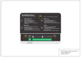
Pro Setup lets you configure how the Nest Thermostat controls each
wire connected to it. When you first enter Pro Setup, you’ll see an image
of the connectors on the Nest base. Connectors with wires will be
highlighted in green or yellow. Green indicates that the wire has only one
setting. Connectors highlighted yellow have multiple options. The Nest
Thermostat selects default settings for these connectors, but you’ll want
to verify or modify these settings to make sure it is controlling each wire
appropriately.
To configure a wire, just turn the thermostat ring to highlight a connector
and press to select it. Each wire will show Type, which describes the function of that wire. In most cases the
Type cannot be changed - it’s dictated by the wiring configuration and by whether or not the system is dual
fuel. The Type for the Star connector is always customizable.
Connectors that control a heating or cooling function will also have a Source setting (to identify the type of
fuel used to heat or cool), a Delivery setting (to describe how heating or cooling is distributed throughout the
home) and a Fan setting (to activate the fan if required). Depending on the wire configuration, the Source or
Delivery settings may have only one default option.
The Fan default is Don’t activate. This means that the Nest Thermostat will rely on the system to activate the
fan when the furnace (W1) is running. If you test the furnace and notice that the fan is not activating, change
this option to Activate. The Fan setting will only change fan activation when the furnace (W1) is running, the
fan will continue to activate normally during other functions.
Source options:
• Gas
• Electric
• Oil
• Propane (LP)
• Geothermal
Delivery options:
• Forced air
• In-floor radiant
• Radiators
• Electric baseboard
(electric source only)
Fan options:
• Activate
• Don’t activate
It's recommended that all connectors highlighted in yellow be reviewed to ensure that the options chosen are
right for that system. After selecting the yellow-highlighted connector, any fields needing attention will be
outlined in blue. Press the Thermostat face to enter that field (the entire field will turn blue). Then turn the ring
to select the correct option for your installation. You must complete this process for every yellow-highlighted
connector and every field outlined in blue within those connectors. If there are no connectors highlighted in
yellow you can turn the ring and select DONE at any time to exit Pro Setup.
19
/