Notas importantes para e[ insta[ador
1. Lea todas las instrucciones contenidas en este manual
antes de instalar el homo,
2, Saque todo el material usado en el embalaje del
compartimiento del horno antes de conectar el suministro
electrico o de gas a la estufa,
3, Observe todos loscodigos y reglamentos pertinentes,
4, Deje estas instrucciones con el consumidor,
5, La puerta del horno se puede quitar para facilitar la
instalaciOn.
6. ESTEHORNO NO ESTA APROBADO PARA LA
INSTALACION DE RIMERO O DA LADO A LADO.
Nota importante al consumidor
Conserve estas instrucciones y el manual del usuario para
referencia futura.
IMPORTANTES DE SEGUR[DAD
• Asegurese de que su homo a pared sea instalada y
puesta a Nerra de forma apropiada pot un
instaJador ca[ificado o pot un tecnico de servicio.
° Este homo de pared debe set electricamente
puesta a tierra de acuerdo con Jos cddigos Joca[es
o, en su ausencia, con et Cddigo E[ectrico National
ANSI/NFPA No. 70-Qltima edicidn en los Estados
Unidos, o e[ Codigo EJectrico Canadiense CSA
Standard C22.1, Part 1, en Canad4.
Pisar, apoyarse, o sentarse sobre ta
puerta de este homo a pared puede resu[tar en
serias Jesiones y tambien puede causar daffos a[
homo a pared.
° Nunca use su homo a pared para calentar et
cuarto. El uso prolongado de la estufa sin la
ventilacion adecuada puede ser peligroso,
La corriente electrica a[ homo debe
estar apagada mientras se hacen las conexiones de
tineas, Si no se apaga, daffos serios o ta muerte
podrian resuItar.
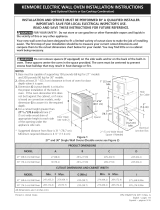
1. CarpinterJa
Consulte lasFiguras 1 y 2 para conocer lasdimensiones
pertinentes al modelo de su horno y al espacio necesario
en el que poner el homo. La superficie donde se va a
apoyar el homo debe de ser de madera contrachapada
solida u otro material similar y. sobre todo, la superficie
tiene que estar a nivel, de lado a lado, y de arras hacia
adelante,
2. Requisitos El6ctricos
Este artefacto debe ser suministrado con el voltaje y la
frecuencia adecuados, y conectado a un circuito
individual correctamente puesto a tierra, protegido por
un cortacircuito o un fusible con el amperio anotado en
la plata de calificaciOn (la plata se encuentra en el
armazon del homo),
Cumpla con todos los cddigos en vigor y todos los re-
gJamentos JocaJes.
1, Parael suministro electrico solamente se necesita
corriente con frecuencia de 60 Hz AC y fase 0nica de
120/208 o 120/240 voltios suministrada por cable de 3 o
de 4 alambres en un circuito separado con fusibles en
ambos lados de la linea (serecomienda un fusible de
tiempo retardado o un cortacircuito), NO ponga un
fusible en el hilo neutro, Eltamarlo del fusible no tiene
que exceder la capacidad del circuito necesario para el
electrodomesticos y la cual se especifica en la placa,
2. Elhorno simple de pared puede consumir un maximo de
4000W a 240Vac, Use un disyuntor de 30 amperes con
un cable #8 AWG, El homo doble de pared puede
consumir un maximo de 8000W a 240Vac, Use un
disyuntor de 40 amperes con un cable #8 AWG,
NOTA: Eltamano de loscables y de las conexiones debe
de estar en conformidad con el tamano del fusible y con la
capacidad del electrodomesticos y de acuerdo con el
Codigo Electrico Nacional ANSI/NFPANo. 70 - t]ltima
edicion, o el Codigo Electrico Canadiense CSA Standard
C22,1, Part 1, y los codigos y reglamentos locales.
No se debe usar una alargadora para
enchufar este e[ectrodomestico. Esto podria
resultar en un incendio, un choque electrico u otto
tipo de daho personal.
3, Esteelectrodomestico debe conectarse a la caja de
fusibles (o de cortacircuito), por medio de un cable
blindado flexible o un cable con forro no metalico, El
cable blindado flexible que va desde el electrodome,stico
debe de estar conectado directamente a la caja de
empalme, La caja de empalme debe de estar Iocalizada
en el lugar que se indica en la Figura 1 o 2, dejando
tanto exceso de cable como sea posiMe entre la caja y
el electrodomestico, de forma que asi el electrodomesti-
co se pueda mover facilmente, si fuera necesario para
hacer una reparaciOn,
4, Se debe de usar un conectador que reduzca latirantez
de una forma adecuada para unir el cable blindado
flexible a la ca]a de empalme,
11