TC Electronic Digital Vintage Reverb Plug User manual
- Category
- Supplementary music equipment
- Type
- User manual
This manual is also suitable for

User Manual
DVR250 NATIVE / DVR250-DT
Digital Vintage Reverb Plug-In with Optional Hardware
Interface and Signature Presets
Rev 2.0

2 DVR250 User Manual
Table of Contents
1. Introduction ............................................................... 4
2. Plug-in Installation .................................................... 5
2.1 Installation on a PC ............................................................. 5
2.2 Installation on a Mac ......................................................... 6
3. Activate your DVR250 iLok License ......................... 7
3.1 Activation when you have
purchased the NATIVE version ............................................... 7
3.2 Get a Free Demo License ................................................. 7
4. Connection and Setup .............................................. 8
4.1 Connecting the DVR250-DT
Desktop Controller (when you have
purchased the DT Desktop Controller version) ............... 8
4.2 Operating the DVR250 ..................................................... 8
4.3 Insert vs Aux Eect............................................................. 8
4.4 Mono/Stereo Operation ................................................... 8
4.5 Travel Period and Module Connection
(when you have purchased the DT version):..................... 9
4.6 Primary and Secondary Controls .................................. 9
4.7 Connection Status to the Hardware Unit ................. 10
5. Plug-in and Hardware Controls .............................. 11
5.1 Primary Plug-in and Hardware Controls ................... 11
5.2 Plug-in Controls - Secondary Parameters ................ 11
5.3 Parameter Details ............................................................. 12
6. Presets ...................................................................... 15
7. Software Updates .................................................... 17
7.1 Hardware Unit Software Updates (optional) ........... 17
8. Specications ........................................................... 17
9. Signal Flow Diagrams .............................................. 18

3 DVR250 User Manual
Important Safety
Instructions
LEGAL DISCLAIMER
LIMITED WARRANTY
Terminals marked with this symbol carry
electrical current of sucient magnitude
to constitute risk of electric shock.
Use only high-quality professional speaker cables with
¼" TS or twist-locking plugs pre-installed. Allother
installation or modication should be performed only
by qualiedpersonnel.
This symbol, wherever it appears,
alertsyou to the presence of uninsulated
dangerous voltage inside the
enclosure-voltage that may be sucient to constitute a
risk ofshock.
This symbol, wherever it appears,
alertsyou to important operating and
maintenance instructions in the
accompanying literature. Please read the manual.
Caution
To reduce the risk of electric shock, donot
remove the top cover (or the rear section).
No user serviceable parts inside. Refer servicing to
qualied personnel.
Caution
To reduce the risk of re or electric shock,
do not expose this appliance to rain and
moisture. The apparatus shall not be exposed to dripping
or splashing liquids and no objects lled with liquids,
suchas vases, shall be placed on the apparatus.
Caution
These service instructions are for use
by qualied service personnel only.
Toreduce the risk of electric shock do not perform any
servicing other than that contained in the operation
instructions. Repairs have to be performed by qualied
servicepersonnel.
1. Read these instructions.
2. Keep these instructions.
3. Heed all warnings.
4. Follow all instructions.
5. Do not use this apparatus near water.
6. Clean only with dry cloth.
7. Do not block any ventilation openings. Install in
accordance with the manufacturer’s instructions.
8. Do not install near any heat sources such as
radiators, heat registers, stoves, or other apparatus
(including ampliers) that produce heat.
9. Do not defeat the safety purpose of the polarized
or grounding-type plug. A polarized plug has two blades
with one wider than the other. A grounding-type plug
has two blades and a third grounding prong. The wide
blade or the third prong are provided for your safety. Ifthe
provided plug does not t into your outlet, consult an
electrician for replacement of the obsolete outlet.
10. Protect the power cord from being walked on or
pinched particularly at plugs, convenience receptacles,
and the point where they exit from the apparatus.
11. Use only attachments/accessories specied by
themanufacturer.
12. Use only with the
cart, stand, tripod, bracket,
or table specied by the
manufacturer, orsold with
the apparatus. When a cart
is used, use caution when
moving the cart/apparatus
combination to avoid
injury from tip-over.
13. Unplug this apparatus during lightning storms or
when unused for long periods of time.
14. Refer all servicing to qualied service personnel.
Servicing is required when the apparatus has been
damaged in any way, such as power supply cord or plug
is damaged, liquid has been spilled or objects have fallen
into the apparatus, the apparatus has been exposed
to rain or moisture, does not operate normally, or has
beendropped.
15. The apparatus shall be connected to a MAINS socket
outlet with a protective earthing connection.
16. Where the MAINS plug or an appliance coupler is
used as the disconnect device, the disconnect device shall
remain readily operable.
17. Correct disposal of this
product: This symbol indicates
that this product must not be
disposed of with household
waste, according to the WEEE
Directive (2012/19/EU) and
your national law. This product
should be taken to a collection center licensed for the
recycling of waste electrical and electronic equipment
(EEE). The mishandling of this type of waste could have
a possible negative impact on the environment and
human health due to potentially hazardous substances
that are generally associated with EEE. At the same time,
your cooperation in the correct disposal of this product
will contribute to the ecient use of natural resources.
For more information about where you can take your
waste equipment for recycling, please contact your local
city oce, or your household waste collection service.
18. Do not install in a conned space, such as a book
case or similar unit.
19. Do not place naked ame sources, such as lighted
candles, on the apparatus.
20. Please keep the environmental aspects of battery
disposal in mind. Batteries must be disposed-of at a
battery collection point.
21. Use this apparatus in tropical and/or
moderate climates.
Music Tribe accepts no liability for any loss which
may be suered by any person who relies either
wholly or in part upon any description, photograph,
or statement contained herein. Technical specications,
appearances and other information are subject to
change without notice. All trademarks are the property
of their respective owners. Midas, Klark Teknik,
Lab Gruppen, Lake, Tannoy, Turbosound, TC Electronic,
TC Helicon, Behringer, Bugera, Auratone and Coolaudio
are trademarks or registered trademarks of Music
Tribe Global Brands Ltd. © Music Tribe Global Brands
Ltd. 2020 All rights reserved.
For the applicable warranty terms and conditions
and additional information regarding Music Tribe’s
Limited Warranty, please see complete details online at
musictribe.com/warranty.

4 DVR250 User Manual
1. Introduction
DVR250 is a groundbreaking reverb unit that brings the iconic EMT 250 Electronic
Reverberator to your DAW. With its original fusion of hardware and software
features, it captures the amazing vintage sound and unique tactile controls of
one of the best-sounding reverb eects ever designed.
The algorithm hails from our celebrated high-end processor platform, the triple
TEC Award-winning System 6000, and oers a sound quality second to none.
For nearly 20 years its sonic magic and depth has been put to the test by brilliant
mixing engineers and musicians around the world, and has shone its vintage
light on countless music, TV and lm projects.
The DVR250 is available both as a pure Native plug-in and with the optional
Desktop Controller as part of the TC ICON series. With their superior algorithms,
fun and intuitive hardware controls and seamless DAW integration, the TC ICON
modules are great additions to any modern studio environment.
Recreating the classic
The development of our emulation has been a process extending several years,
with the goal of recreating the EMT 250. As part of our extensive research,
we tracked down two of the few original units that have survived years of wear
and tear. Fortunately they were both particularly great-sounding units!
After refurbishing and measuring the two units, our cross-disciplinary team
rened and polished the algorithm to make sure the DVR250 captures all
the nuances that made the original stand out, down to the most minute
spectral characteristics.
On top of recreating the legendary reverb sound, we also included the ve
additional eects that the original boasted, namely chorus, echo, delay, phasing
and space.
Making the DVR250 involved engineers and specialists within a multitude of
design disciplines:
Hardware technical:
What was the precision of the converters and how were they implemented in
the 80s with regard to emphasis, block scaling, linearity, lters et cetera? How
much processing and RAM was available in the original unit? What was the
sample rate?
Software technical:
Which kind of processing was done in the discrete circuitry, and what type of
truncation and noise oor artifacts would result? How could the low sample
rate be mimicked precisely, and how could all of this be transferred to a modern
native processing platform?
Perceptual:
Making sure the qualities of the original processor was preserved. Sweet
modulation, spectral characteristics, spaciousness, distortion, saturation etc.
Hundreds of hours spent listening and measuring!
User:
The four basic parameters of the EMT 250 were carefully laid out, oering a
remarkably simple user interface with complex, yet optimized interactions under
the hood. DVR250-DT is a resemblance of that including range and coarseness
of parameters.
About this manual
Read this manual to learn how to install and use your TC Electronic DVR250 reverb
unit. This manual is only available in PDF format from the TC Electronic website.
To get the most from this manual, please read it from start to nish, or you may
miss important information.
To download the most current version of this manual, visit the web page:
www.tcelectronic.com/Categories/c/Tcelectronic/Downloads
If you still have questions about your TC Electronic product after reading its
manual, please get in touch with TC Support:
www.tcelectronic.com/brand/tcelectronic/support

5 DVR250 User Manual
2. Plug-in Installation
Visit www.tcelectronic.com/dvr250-dt/support/ to download the installer
le. The plug-in requires either an iLok license (delivered when you purchase
the NATIVE version) or the DVR250 DT Desktop Controller (when you purchase
the DT Desktop Controller version) or an iLok Trial License. All parameters are
available in the plug-in and most are available on the DT Desktop Controller.
Select the Mac or PC version and save the le to your hard drive. The latest
rmware for the DVR250 Desktop Controller will be included in the software
as well.
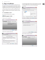
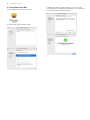
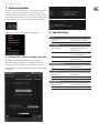
2.1 Installation on a PC
Open the zip le and double click the executable le.
Follow the steps in the Setup Wizard.
Accept the license agreement and click ‘Next’.
Select which VST and/or AAX components you want to install. Pro Tools uses AAX
and most other DAW programs use VST. The installer will oer a default location
to save the le, but you can choose another location by clicking the
‘Browse’ button.
Click ‘Next’ to begin the installation.
When installation is complete, click ‘Finish’.

6 DVR250 User Manual
2.2 Installation on a Mac
Open the zip folder and double click the installer icon.
Proceed through the prompts to begin installation.
A default location will be selected for installation, or you can select another
folder manually. If you have administrator authorization in place, you will need to
enter your password before beginning installation.

7 DVR250 User Manual
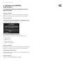
3. Activate your DVR250
iLok License
3.1 Activation when you have purchased the
NATIVE version
Step 1: Install iLok
The rst step is to create an iLok user account at www.iLok.com and install the
PACE iLok License Manager on your computer if it’s your rst time using iLok.
Step 2: Activation
In the received mail (when buying the NATIVE version) you will nd your personal
Activation Code. To activate your software, please use the Redeem an Activation
Code feature in the PACE iLok License Manager.
3.2 Get a Free Demo License
Make use of this hassle-free oer to try out our plug-ins before you buy.
• • 14-Day Trial Period
• • Fully Functional
• • No Feature Limitations
• • No Physical iLok Key Needed
Step 1: Install iLok
The rst step is to create a free iLok user account at www.iLok.com and install the
PACE iLok License Manager on your computer if it’s your rst time using iLok.
Step 2: Get your free license
Go to http://www.tcelectronic.com/brand/tcelectronic/free-trial-DVR250-native
and enter your iLok User ID.
Step 3: Activation
Activate your software in the PACE iLok License Manager.

8 DVR250 User Manual
4. Connection and Setup
4.1 Connecting the DVR250-DT Desktop
Controller (when you have purchased the DT
Desktop Controller version)
Getting the Desktop Controller up and running couldn’t get any easier. Plug the
included USB cable into the unit’s rear micro-USB port, and connect the other end
to a free USB port on your computer. The Desktop Controller is bus powered so no
other power cables are necessary, and no additional drivers need to be
manually installed.
The Desktop Controller will light up upon successful connection. You can now
apply the plug-in to a channel in your DAW to begin using the eect. This process
may vary slightly depending on your software, but generally should require
these steps:
• • Select a channel or bus in your DAW to which you would like to add the
eect Access the mixer page where you should see a section dedicated to
eect slots
• • Open the menu where you can select from a list of eect types, which
probably includes many stock plugins that are included with the DAW.
There should be submenu to view general VST/AU/AAX options.
• • The plug-in will likely be found in a dedicated TC Electronic folder. Select the
DVR250 and it will now be added to the signal chain.
Double click on the eect slot that contains the DVR250 to view the plug-in UI.
There should be a green link icon at the bottom, and text that indicates successful
connection between the plug-in and the Desktop Controller.
Note: The iLok License Manager needs to be installed on your computer also if
you have purchased the DT Desktop Controller version. In this case you don’t need
to create an iLok account or activate any license.
4.2 Operating the DVR250
After you have installed the plug-in, and either activated the iLok license or
connected the DVR250-DT Desktop Controller via USB, you can begin inserting
the plug-in to your tracks.
Adjustments to the eect are done in two ways. Either by using the plug-in user
interface or via the physical Desktop Controller.
4.3 Insert vs Aux Eect
The DVR250 can be inserted directly into an eect slot on a single channel,
as described above, which passes the entire signal through the eect.
However, the DVR250 can also be added to an auxiliary bus, and one or more
channels can send a portion of their signal to this bus to be processed by the eect.
The output of the eect is then mixed back in with the rest of the tracks. This
diers from an insert eect in that the DVR250 isn’t aecting the track’s entire
signal, so modulation eects like the Chrous and static Phase in DVR250 generally
shouldn’t be used this way. In this setup, the Mix parameter should always be set
to 100%.
4.4 Mono/Stereo Operation
The DVR250 can be used both as a mono instance on mono tracks and a stereo
instance on stereo tracks. Depending on the specic DAW, a mono in/stereo out
may also be available.
In the case of a mono out instance, the output signal is made by outputting the
left plug-in channel only.
DVR250
Laptop

9 DVR250 User Manual
4.5 Travel Period and Module Connection (when you have purchased the DT version):
You can try out the plug-in before purchasing or receiving your purchased Desktop Controller by requesting a Free iLok Trial License, which will enable full functionality
for 14 days. When you receive and connect your purchased Desktop Controller you will no longer need an iLok License to have full functionality in the plug-in or via the
Desktop Controller.
60-day Travel Period
If the Desktop Controller is disconnected, full plug-in functionality will be available for 60 days, after which the plug-in requests re-connection to the hardware unit.
Once the hardware unit is re-connected, all controls become available.
Download and install the
plug-in and connect
the module
Disconnect Module 60 days... Reconnect Module
Full Fuctionality
Processing, controls
available for 60 days
countdown
Processing Only Full Fuctionality Restored
60 day count downLink to product page
with store nder
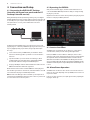
4.6 Primary and Secondary Controls
After you have installed the plug-in and activated the iLok license or connected
the DVR250 via USB, you can begin adding the eect to your tracks.
The plug-in is divided into two sections, which are both visible when the “I+II”
button at the top left is selected. The left section is identical to the hardware unit
and could be considered Primary parameters. These include common items such
as delay time and feedback.
The right side contains the Secondary parameters.
To reduce plug-in size on your screen you can select “I” or “II” in the top left of
the plug-in. “I” will show the left section of the plug-in only and “II” will show
the right section. Setting “II” can be a complementary setting when using the
hardware unit.”
All of these parameters will be discussed in detail later in this manual.

10 DVR250 User Manual
4.7 Connection Status to the Hardware Unit
The TC Icon family all use the same method to show the connection status between
the plug-in and the hardware unit.
Connection status is indicated on the lower left side of the plug-in window.
Successful connection is indicated with a green chain icon. When using the
NATIVE version only, this chain icon will remain grey.
There are 3 conditions that will result in a “Not connected” status. If another
instance of the plug-in already exists on another track, the chain icon will
appear yellow with a yellow frame, and the text box will notify you where the
plug-in is currently active. Click the chain icon to connect the hardware unit to
the new plug-in location. The yellow icon may also appear while the connection
is being made between the DVR250 unit and the plug-in, accompanied by
“Connecting...” text.
If the hardware unit is disconnected from the computer, but the countdown has
not yet expired, a yellow chain icon without the yellow frame will appear.
See “Travel Period and Module Connection” section for details.
All other “Not connected” states are indicated by a red chain icon. This could
happen if the USB cable is disconnected, the DVR250 connection is disrupted,
or other issues.
To summarize the connection status possibilities:
Most DAWs oer the ability to move or drag plug-ins from one track/bus to
another, and DVR250 supports this as well.
Most DAWs also feature an on/o switch for plug-ins, accessible inside the
plug-in window and/or the track itself. Muting the plug-in will make the eect
inaudible, but will not shut down the connection to use the hardware unit.

11 DVR250 User Manual
5. Plug-in and Hardware Controls
Control of the DVR250 is done in the plug-in or optionally done using the
hardware unit (when you have purchased the DT version). All primary parameters
of the DVR250 are also accessible through the DT Desktop Controller. These
include parameters that control major parts of the eect, such as reverb decay,
delay time, and much more. Secondary parameters that are needed less-often
are handled in the plug-in window.
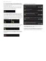
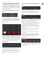
5.1 Primary Plug-in and Hardware Controls
Meters
The meter section gives feedback about the incoming and outgoing audio
signals. The input level displays the audio as it enters the plug-in, and is not
aected by adjustments to the input level control or any other parameter.
The output meter is aected by the results of the eect as well as the output
level control parameter.
Levers
Use the 4 levers to make primary parameter adjustments. The function of each
lever depends on the eect selected and the state of the SET button. A quick
reference of the active parameters can be viewed in the Lever Status section of
the plug-in, and full descriptions are detailed in chapter 5.3. In the plug-in, the
levers can be controlled either by mouse-clicking on the upper or lower part of
the Lever handle or by using the mouse wheel over the Lever handle.
Program Buttons
Activate an eect with the program buttons. The currently-selected eect will be
indicated by a lit LED. Only one eect can be activated at a time.
Pressing an already-lit button will bypass the eect and cause the LED to ash.
Pressing again or selecting a dierent eect will reactivate the eect.
The SET button accesses a 2nd tier of parameters that can be adjusted with
the levers.
5.2 Plug-in Controls - Secondary Parameters
Levels
Click and drag up or down to adjust the input and output levels from 0 to 99.
A setting of 0 is -∞, and a setting of 1 is -96 dB. The level increases in 3 dB
increments at lower settings, and by 0.5 dB increments above -40 dB.
Vintage
These parameters are emulations of the classic hardware unit on which this
plug-in is based. If desired, the sound can emulate limited bandwidth and bit
resolution to achieve a more authentic, slightly grainy sound.
Adjust the Hi Cut frequency to roll o some of the upper frequencies. The QScale
parameter emulates internal EQ adjustments found on classic reverb units,
and can be used in conjunction with the Hi Cut to tailor the high end.
The Input Trans emulates the sound of input transformers typically found in
vintage reverbs. Use it to create warm, vintage sounds, especially when using
short decay times.
The Trim Lo Frq button engages subtle attenuation of certain low frequencies.
Use the Lo Res button to simulate a lower bit resolution for a grainy,
vintage sound.
The Vintage settings that emulate the original EMT 250 are: Hi Cut 11 kHz,
QScale 1.2, Lo Res On.
The settings of the Vintage section aect all eect types selected with the
Program buttons on the hardware unit. This enables creative possibilities like
setting a Hi Cut for only the detuned part of the signal in the Chorus eect,
and hereby ensuring modulation only on low frequencies.
Lever Status
This section indicates the parameters that are adjustable with the levers for the
currently-selected eect. An additional layer of parameters can be accessed by
engaging the SET button.

12 DVR250 User Manual
Mix
Click and drag the numbers inside each eect box to adjust the mix settings. Mix
is also directly accessible from the hardware unit for all eects by engaging the
SET button and using the white (left) lever.
Lock Symbol
Some of the parameters can be locked from being recalled when a new preset
is selected. Locked parameters will always keep their values no matter which
preset you recall.
This is especially useful with the Mix parameter.
The default presets provided in the plug-in are typically created with the intent
that the eect will be inserted on the track (as an insert eects). A Mix value has
been chosen that will work for that preset.
However, if you’d like to use the DVR250 as a send/parallel eect, the Mix
parameter should typically be set to 100%. After setting the Mix to 100%, use the
lock function to make sure it stays at 100% even if you load another preset.
Preset
Use the Preset section to recall and save presets as well as assign presets as
favorites. The Preset Up/Down arrow buttons can also be used for browsing
through the available presets. See Chapter 5 for details.
Bottom Section
The bottom portion of the plug-in window displays connection status as well as
plug-in instance name, and has several options available.
The green chain icon indicates successful connection between the hardware unit
and the plug-in. Connection issues will be indicated by yellow or red icons; see
Chapter 3 for details.
The current name of the plug-in instance appears in the middle eld. If the DAW
is able to provide the name of the track where the plug-in instance is inserted,
the plug-in instance will be named after the track name. The instance can be
renamed by clicking the pencil icon.
If you install the plug-in without connecting the hardware unit to your computer,
a red dot will appear on the shopping cart icon. This will link you to more
information about buying the DVR250 unit. Once the plug-in detects a connected
hardware unit, the red dot will disappear.
The Settings icon accesses a menu with several links and options. This user
manual is available, along with links to the TC Electronic website, relevant news,
additional signature artist presets, and the user license agreement. If a red dot
appears over the Settings icon, a new version of the plug-in or rmware may be
available. Click “Check for Updates” to download and install the new le.
See Chapter 6 for details.
With the “Help” option selected, hovering the mouse over a certain item in the
plug-in window will give a brief description of the parameter’s function.
With the “Take over on focus” option selected, the currently-viewed plug-in
instance will take over control of the physical hardware unit as soon as it is
brought into focus.
When a new instance of the plug-in is inserted on a track or bus, that instance
will take over immediately if the “Take over on insert” option is checked.
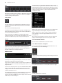
5.3 Parameter Details
All 6 of the eects in the DVR250 will be described in detail here.
5.3.1 Eect selection / navigation
Press one of the program buttons at the bottom of the hardware unit to select
the desired eect. The associated LED will light.
Looking at the plug-in window, the primary parameters will appear in the Lever
Status section.
Pressing the SET button will cause a secondary bank of parameters to appear.
Secondary parameters for the reverb eect:

13 DVR250 User Manual
The 4 parameter slots indicate the parameters that are now available for
adjustment via the 4 levers on the hardware unit.
The levers often control certain types of parameters regardless of which eect is
selected. For example, the 4th lever always controls the predelay as long as the
primary set is active (SET button o). The rst lever tends to control the primary
time parameter for each eect.
The silkscreen gives clues about the function of each lever's primary function.
Primary levers:
1. Time (t)
2. Low frequencies (>)
3. High frequencies (<)
4. Predelay (+td)
However, some of the eects deviate from this pattern. You can always check the
plug-in window if you forget the parameter mapping.
With the SET knob engaged, the rst lever will always adjust the eect’s
mix parameter.
Secondary levers:
1. Mix
2. Modulation
3. Output select
4. Not used
While the Mix is always conveniently adjustable with the 1st lever when SET is
engaged, this parameter can also be adjusted on the plug-in window. Either click
and drag the mix value up or down with the mouse, or double click and enter a
specic value.
5.3.2 Reverb
The reverb eect in the DVR250 faithfully recreates a classic algorithm that has
been used on countless hit records.
Primary parameters
1. Decay – The main reverb decay tail is controlled by the rst lever. The value
is indicated by the red LEDs on the left side of the lever scale, and range from
0.4 to 4.5 seconds.
2. Lo Decay – The low frequency decay time is controlled by lever 2.
The settings are indicated as multipliers of the main decay time set by lever
1, selectable between x 0.5, x 1.0, x 1.5, and x 2.0.
3. Hi Decay – The high frequency decay time is controlled by lever 3.
The settings are indicated as multipliers of the main decay time set by lever
1, selectable between x 0.25, x 0.33, x 0.5, and x 1.0 (max).
4. Predelay – Sets the amount of delay before processing takes eect,
selectable between 0, 20, 40 and 60 ms.
Secondary parameters (enable SET)
1. Mix – Determines how much of the processed signal is mixed with the dry
signal. A setting of 50% yields an even blend of wet and dry signals.
2. Modulation – Adjusts the amount of modulation in the reverb tail.
Available settings are 0%, 5%, 40% and 80%.
3. Out Select – Selects between the front L/R outputs and rear L/R
outputs, which have slightly dierent sounds on the original classic reverb
unit. The outputs can be used in a great way to create a de-correlated
quadraphonic surround reverb. This is done by using front and rear outputs
in 2 plug-in instances respectively to drive 4 output channels in total.
These could be feeding L/R front and L/R rear speakers in a 5.1 setup.
Note: If it is a stereo instance, the signal is mixed to mono before the
BASIC DELAY block.
5.3.3 Delay
The delay eect oers 4 individual clean digital echoes that are adjustable for the
left and right channels. The routing of each delay tap is arranged like this:
I: Left to left
II: Right to right
III: Right to approx. 75% to the left
IV: Left to approx. 75% to the right
Primary parameters
1. Tap Coarse – Sets the delay time in 20 ms increments from 0 to 300 ms for
the currently-selected tap (I-IV).
2. Tap Fine – Sets the ne delay time in addition to the setting of lever 1,
adjustable between 0, 5, 10 or 15 ms.
3. Tap Select – Selects which tap is controllable by the other
levers (I, II, III, IV).
4. Predelay – Sets the amount of delay before processing takes eect,
selectable between 0, 20, 40 and 60 ms.
Secondary parameters (enable SET)
1. Mix – Determines how much of the processed signal is mixed with the dry
signal. A setting of 50% yields an even blend of wet and dry signals. 0% mix
corresponds to setting “0.4”, 25% mix to “1.0”, 50% to “2.0”, 75% to “3.0”
and 100% to “4.5".
2. Tap Level – Adjusts the output level of the currently-selected delay tap,
selectable between -2, -8, -16, -120 dB.
3. Tap Select – Duplicate location for the Tap Select found on the primary
parameter set.
4. Lever not used.

14 DVR250 User Manual
5.3.4 Phase
Primary parameters
A classic comb ltering phase eect is available with basic parameter controls.
1. Curve – Adjusts the phase shift between the signals that create the comb
lter eect. The eect does not automatically oscillate like other phase
eects, so lever 1 can be used to manually adjust the time shift.
2. Lever not used.
3. Lever not used.
4. Predelay – Sets the amount of delay before processing takes eect,
selectable between 0, 20, 40 and 60 ms.
Secondary parameters (enable SET)
1. Mix – Determines how much of the processed signal is mixed with the dry
signal. A setting of 50% yields an even blend of wet and dry signals. 0% mix
corresponds to setting “0.4”, 25% mix to “1.0”, 50% to “2.0”, 75% to “3.0”
and 100% to “4.5".
2. Lever not used.
3. Out Select – Selects between the front L/R outputs and rear L/R outputs,
which have slightly dierent sounds on the original classic reverb unit.
4. Lever not used.
Note: If it is a stereo instance, the signal is mixed to mono before the t1 block.
(see Signal Diagrams in Chapter 8)
5.3.5 Chorus
The chorus eect adds several time-shifted duplications of the original signal,
giving a thicker texture to the sound. It is designed to be great for both chorus-
sensitive instruments like piano and strings as well as chorus-hungry instruments
like distorted guitar.
Primary parameters
1. Lever not used.
2. Modulation – Adjusts the modulation depth.
3. Tap Enable – Selects how many time-shifted voices are present, giving a
more intense eect. Settings are I, I+II, I+II+III, and I+II+III+IV.
4. Predelay – Sets the amount of delay before processing takes eect,
selectable between 0, 20, 40 and 60 ms.
Secondary parameters (enable SET)
1. Mix – Determines how much of the processed signal is mixed with the dry
signal. A setting of 50% yields an even blend of wet and dry signals. 0% mix
corresponds to setting “0.4”, 25% mix to “1.0”, 50% to “2.0”, 75% to “3.0”
and 100% to “4.5".
2-4. Levers not used.
5.3.6 Echo
This is a mono echo eect that may be easier to use than the Delay program.
It’s a unique echo eect in that Lo and Hi Mult aect the feedback as “decay
multipliers” similar to the reverb rather than applying a Lo and Hi Cut in the
feedback as typical Echo eects do.
Primary parameters
1. Time Coarse – Sets the delay time in 20 ms increments from 0 to 300 ms.
2. Time Fine – Sets the ne delay time in addition to the setting of lever 1,
adjustable between 0, 5, 10 or 15 ms.
3. Feedback – Adjusts the number of repeats.
4. Predelay – Sets the amount of delay before processing takes eect,
selectable between 0, 20, 40 and 60 ms.
Secondary parameters (enable SET)
1. Mix – Determines how much of the processed signal is mixed with the dry
signal. A setting of 50% yields an even blend of wet and dry signals. 0% mix
corresponds to setting “0.4”, 25% mix to “1.0”, 50% to “2.0”, 75% to “3.0”
and 100% to “4.5".
2. Lo Mult – Adjusts the low frequency damping of the repeats.
3. Hi Mult – Adjusts the high frequency damping of the repeats.
4. Lever not used.
5.3.7 Space
The space reverb has a very long decay and minimal parameter adjustments.
It can be used as a special eect for creative purposes.
Primary parameters
1-3. Levers not used.
4. Predelay – Sets the amount of delay before processing takes eect,
selectable between 0, 20, 40 and 60 ms.
Secondary parameters (enable SET)
1. Mix – Determines how much of the processed signal is mixed with the dry
signal. A setting of 50% yields an even blend of wet and dry signals. 0% mix
corresponds to setting “0.4”, 25% mix to “1.0”, 50% to “2.0”, 75% to “3.0”
and 100% to “4.5".
2-4. Levers not used.

15 DVR250 User Manual
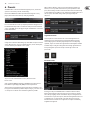
6. Presets
The DVR250 oers a collection of default and signature presets, as well as the
option to create and save your own custom settings.
Note that most DAWs have a built-in preset function that appears on every
plug-in, which is often found at the top of the plug-in window.
It is not recommended to use this as your primary method of saving presets as it
has limited functionality and does not allow the saved presets to be transferred
easily to other DAWs. Instead, we suggest using the included Preset section at the
bottom of the window:
A single click on the Preset window brings up a menu with several preset-related
options. Recall a factory or user preset from the libraries, save the current preset,
or create a new user preset with the ‘Save as’ option.
The presets menu is divided between a Factory Presets and a User
Presets section.
As the reverb of the DVR250 is identical to the DVR2 in System 6000, there is a
folder with the original high-quality DVR2 presets from System 6000.
The Factory Presets are built into the plug-in and cannot be overwritten, so if a
factory preset is modied and you’d like to keep the changes, you need to save it
as a user preset. User Presets can be edited and organized as you’d like.
When recalling a default or saved preset, the name will appear in plain text.
However, as soon as you make an alteration to any of the parameters in that
preset, the text changes to italics to indicate a deviation. This is also indicated by
a red dot after the preset number. You can click in the Preset window, then select
the Save option, or discard the changes when you navigate away from
that preset.
Signature Presets
The Factory Presets section includes a sub-section called Signature Presets.
Signature Presets are custom-made presets designed by world-class artists
and recording engineers. The library of signature presets is constantly being
expanded, and you can check for more Signature Presets that might be available
for download by accessing the Settings menu and selecting ’Signature Presets’.
Factory and Signature presets have unique icons that appear next to the
preset name.
Favorite Preset
Creating your own presets will make them accessible from the Preset menu,
but they will only appear in the list of 100 presets if you set them as a favorite.
This is done by assigning a favorite slot number to the preset using the Favorite
menu. Recall one of your custom presets, then click the Assign button and choose
an available slot in one of the 10 banks. Some of the factory presets also by
default reside in these banks. These assignments can easily be overwritten by
using Remove Assignment.

16 DVR250 User Manual
When a preset is assigned a favorite slot number, that slot will be locked so
that other presets cannot be assigned to the same location. This is shown in the
Favorite menu by graying out the number in question. The favorite number will
also be displayed in brackets next to the associated preset when you browse the
presets menu.
You can remove the favorite assignment by selecting the “Remove Assignment”
feature in the Favorite menu, then saving the preset.
Arrow Buttons
The Preset window also has Up/Down arrow buttons that allow presets to
be scrolled sequentially. This can include all Factory and User presets, or only
Favorites, depending on the ’Browse Favorites Only’ setting.
Browse Favorites Only
This option lters the presets that appear in the main preset list so that only
favorites are selectable using the Up/Down arrow buttons on the preset window.
Make Current Preset Default
Selecting ’Make current preset default’ will cause this preset to appear every time
a new instance of the plug-in is created.
Reveal User Preset Folder in Explorer
To change the name of a preset, select ‘Reveal User Preset Folder in Explorer’
and modify the le name. This will open a Finder (Mac) or Explorer (PC) window
where the user presets are stored. You can rename as well as delete, copy
and paste presets. This allows you to share presets with other users online,
simply pasting the new ones in this folder.

17 DVR250 User Manual
7. Software Updates
New versions of the software may be released to add new features and improve
performance. Updates can be detected from the plug-in directly and can be
installed after download from the website. See Chapter 2 for plug-in installation.
If the ’Automatically check for updates’ option is checked inside the update menu,
the red dot will appear on the settings icon when a new plug-in is available.
Click the gear icon and select “Check for Updates” to perform a scan.
7.1 Hardware Unit Software Updates (optional)
The hardware unit rmware will be included in each plug-in update.
After you have installed a new plug-in, the system will detect mismatched
rmware and indicate a need for update via a small red dot on the gear icon.
Click the “Upgrade to x.x.xx” eld to start the update. Progress will be indicated
in the plug-in.
8. Specications
Sound
Sample rates 44.1, 48, 88.2, 96, 176.4, 192 kHz
Software Support
Operating systems Mac OS X 10.10 Yosemite or above,
Windows 7 or above
Drivers No additional drivers required,
uses standard USB HID drivers
Plugin formats AAX-native, Audio Units,
VST2.4, VST3. 32/64 bit
USB Connection (DT version)
Type USB 2.0, type micro-B
Power (DT version)
Power supply USB bus powered
Power consumption Max. 2.5 W
Physical (DT version)
Dimensions (H x W x D) 52 x 109 x 133 mm (2 x 4.3 x 5.2")
Weight 0.5 kg (1.1 lbs)

18 DVR250 User Manual
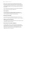
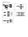
9. Signal Flow Diagrams
Reverb
Delay
Phase
Chorus
Echo
Output
Discorrelator
and
Demultiplexer
Basic delay
Reverberation
Reverberation0...60 ms
1st Reection
I
IV
III
II
t
1
t
17
t
19
t
2
t
16
t
V
t
N
t
N
t
N
L
t
0...60 ms
t
I
0...3/5 ms
t
IV
0...3/5 ms
R
L
R
t
0...60 ms
t
III
0...3/5 ms
t
II
0...3/5 ms
IV
II
III
I
0...60 ms 0...15 ms
t
1
t
2
15 ms
t
3
+
+
+
+
+
+
+
+
+
+
–
–
I
II
IV
III
0...60 ms
k
t
1
t
4
k
t
5
III
IV
k
t
3
k
t
2
II
I
t
0...60 ms
t
0...60 ms
+
L
Hi + Lo
+
R
L
R
Feedback

19 DVR250 User Manual
FEDERAL COMMUNICATIONS
COMMISSION COMPLIANCE
INFORMATION
Responsible Party Name: Music Tribe Commercial NV Inc.
Address: 901 Grier Drive
Las Vegas, NV 89118
USA
Phone Number: +1 702 800 8290
DVR250
complies with the FCC rules as mentioned in the followingparagraph:
This equipment has been tested and found to comply with the limits for a ClassB
digital device, pursuant to part 15 of the FCC Rules. These limits are designed
to provide reasonable protection against harmful interference in a residential
installation. This equipment generates, uses and can radiate radio frequency
energy and, if not installed and used in accordance with the instructions, may cause
harmful interference to radio communications. However, there is no guarantee that
interference will not occur in a particular installation. If this equipment does cause
harmful interference to radio or television reception, which can be determined
by turning the equipment o and on, the user is encouraged to try to correct the
interference by one or more of the followingmeasures:
• • Reorient or relocate the receiving antenna
• • Increase the separation between the equipment and receiver
• • Connect the equipment into an outlet on a circuit dierent from that to which the
receiver is connected
• • Consult the dealer or an experienced radio/TV technician forhelp
This device complies with Part 15 of the FCC rules. Operation is subject to the
following two conditions:
(1) this device may not cause harmful interference, and
(2) this device must accept any interference received, including interference that may
cause undesired operation.
Important information:
Changes or modications to the equipment not expressly approved by Music Tribe
can void the user’s authority to use the equipment.
DVR250

-
 1
1
-
 2
2
-
 3
3
-
 4
4
-
 5
5
-
 6
6
-
 7
7
-
 8
8
-
 9
9
-
 10
10
-
 11
11
-
 12
12
-
 13
13
-
 14
14
-
 15
15
-
 16
16
-
 17
17
-
 18
18
-
 19
19
-
 20
20


TC Electronic Digital Vintage Reverb Plug User manual
- Category
- Supplementary music equipment
- Type
- User manual
- This manual is also suitable for
Ask a question and I''ll find the answer in the document
Finding information in a document is now easier with AI
Related papers
-
TC Electronic TC8210 NATIVE / TC8210-DT User manual
-
TC Electronic Midas-Powered High-End Dynamics Channel Plug-In User manual
-
TC Electronic BRICKWALL HD NATIVE / BRICKWALL HD-DT Owner's manual
-
TC Electronic PEQ 3000 NATIVE / PEQ 3000 -DT User manual
-
TC Electronic DVR250-DT Quick start guide
-
TC Electronic TC8210 NATIVE / TC8210-DT Quick start guide
-
-
-
-
 tc electonic DYN 3000-DT Midas-Powered High-End Dynamics Channel User guide

Other documents
-
Solid State Logic Duende Native downloads User guide
-
 TC electronic SDN BHD DVR2 User manual
-
 Native Instruments RAUM Owner's manual
-
 Xils Lab XILS 4 Owner's manual
-
Eventide Tverb User guide
-
-
SINEVIBES Blend v2 User manual
-
Xils Lab XILS 3 Owner's manual
-
Xils Lab Syn'X 2 Owner's manual
-
SINEVIBES Luminance c2 User guide


