Multi-Link ML-001 User manual
- Category
- Security access control systems
- Type
- User manual
This manual is also suitable for

P/N. 101Z379-001
FEB, 2011
PATENTED
©2011 SKYLINK GROUP
Home Smart Center
www.skylinkhome.com
CUSTOMER SERVICE
17 Sheard Avenue, Brampton, Ontario, Canada L6Y 1J3
Tel : (905) 456-8883
Fax : (905) 456-7819
Email : [email protected]
MODEL: ML-001 / ML-100
TM
®

Home Smart Center
USER'S INSTRUCTIONS
English

IMPORTANT SAFETY INSTRUCTIONS
When using your telephone equipment, basic safety precautions should
always be followed to reduce the risk of fire, electric shock and injury to
persons, including the following:
1. Do not use this product near water, for example, near a bath tub, wash
bowl, kitchen sink or laundry tub, in a wet basement or near a swimming
pool.
2. Avoid using a telephone (other than a cordless type) during an
electrical storm. There may be a remote risk of electric shock from
lightning.
3. Do not use the telephone to report a gas leak in the vicinity of the leak.
4. Use only the power cord and batteries indicated in this manual. Do not
dispose of batteries in a fire. They may explode. Check with local codes
for possible special disposal instructions.
5. Plug the adaptor to the socket-outlet that near the equipment and
shall be easily accessible.
SAVE THESE INSTRUCTIONS
Attention
This product is not an alarm system providing facilities to summon
assistance, for use by persons who can be considered to be living
at risk. This product is not intended to for use in health care signaling
equipment or directly connect to central-station (Police, Medical, Fire).
–1–

–2–
IC Statement
‘’This product meets the applicable Industry Canada technical
specifications.”
Before installing this equipment, users should ensure that it is permissible
to be connected to the facilities of the local telecommunications com-
pany. The equipment must also be installed using an acceptable method
of connection. In some cases, the company’s inside wiring associated
with a single line individual service may be extended by means of a
certified connector assembly (telephone extension cord). The customer
should be aware that compliance with the above conditions may not
prevent degradation of service in some situations.
Repairs to certified equipment should be made by an authorized Canadian
maintenance facility designated by the supplier. Any repairs or alterations
made by the user to this equipment, or equipment malfunctions, may give
the telecommunications company cause to request the user to disconnect
the equipment.
Users should ensure for their own protection that the electrical ground
connections of the power utility, telephone lines and internal metallic water
pipe system, if present, are connected together. This precaution may be
particularly important in rural areas.
Caution: Users should not attempt to make such connections themselves,
but should contact the appropriate electric inspection authority, or electri-
cian, as appropriate.
‘’The Ringer Equivalence Number is an indication of the maximum
number of terminals allowed to be connected to a telephone inter-
face. The termination on an interface may consist of any combination
of devices subject only to the requirement that the sum of the Ringer
Equivalence Numbers of all the devices does not exceed five.’’
–55–
Declaration of Conformity
Application of Council Directive(s) :
Radio Equipment and Telecommunication Terminal Equipment
Directive (1999/5/EC) - R&TTE
Standard(s) to which Conformity is Declared:
EMC:
EN 55022:1998+A1: 2000, EN 610000-3-2: 2000,
EN 61000-3.3: 1995 +A1:2001, EN 55024: 1998+A1: 2001,
EN 50130-4: 1995/A1: 1998, EN 300220-3: 2000,
EN 301489-3: 2002
Safety:
EN 60950-1: 2001, EN 50371: 2002
Telephony:
TBR 21: 1998
Manufacturer’s Name: Capital Prospect Limited
Manufacturer’s Address: Room 3, 13/F, Block B, Veristrong Industrial Centre,
36 Au Pui Wan Street, Fo Tan, N.T., Hong Kong
Type of Equipment: Home Smart Center
Model No.: AM-002
Serial No.: Not Labelled
Year of Manufacture: 2005
I, the undersigned, hereby declare that the equipment specified above conforms to the above
Directive (s) and Standard(s).
Place: Hong Kong
Joe Ng
Project Manager
Date: 21st July 2005
..........................................................................................
..........................................................................................
..........................................................................................
..........................................................................................
..........................................................................................
..........................................................................................
..........................................................................................
................................................
................................................

–3–
CONTENT
Introduction..........................................................................................................................4
Overview........................................................................................................................4
Installation...........................................................................................................................7
Installing the Console.................................................................................................7
Programming Passwords..........................................................................................9
Phone Number Programming..................................................................................10
Contact ID Phone number.......................................................................................12
Phone Number Programming (Calling to Central Monitoring Station)................12
Account Number Programming..................................................................................13
Deactivating the Digital Dialer.................................................................................14
Installing Door/Window Sensors................................................................................15
Installing Motion Sensor..........................................................................................16
Operation..........................................................................................................................18
Alert mode...................................................................................................................18
Mute....................................................................................................................................19
System Status..............................................................................................................20
Arming The System.....................................................................................................20
Disarming the system...............................................................................................21
Disarming a triggered control panel.....................................................................22
Disarming under Duress..........................................................................................22
Panic...................................................................................................................................23
System Failure............................................................................................................23
Phone Line Failure............................................................................................23
Sensor Failure.....................................................................................................24
Low Battery...........................................................................................................24
Coummunication.............................................................................................................26
Receiving an emergency call..................................................................................26
Remote Operation by Telephone...........................................................................27
To access the control panel away from home......................................................27
Advanced Programming.................................................................................................29
Zone Dependent Setting – Beep / Alarm..............................................................29
Zone Dependent Setting – Auto Mute....................................................................32
Zone Dependent Setting – Alert Zone (Bypass zone).........................................33
Learn Keychain / Keypad Remotes........................................................................35
Erase Keychain / Keypad Remotes........................................................................36
Learn Sensors..............................................................................................................37
Sensor Location Selection Guide.............................................................................37
Erase Sensors...........................................................................................................39
Home Automation.............................................................................................................40
Learn Control Modules............................................................................................40
Erase Control Modules............................................................................................43
Event Trigger..............................................................................................................45
Trouble Shooting..............................................................................................................47
Accessories......................................................................................................................49
System Configuration.....................................................................................................53
FCC Information................................................................................................................53
CE........................................................................................................................................55
g) Should you experience trouble with this equipment, please contact
Skylink Customer Support at 1-800-304-1187 for repair or warranty
information. If the equipment is causing harm to the telephone network,
the telephone company may request that you disconnect the equipment
until the problem is resolved.
h) Please follow instructions for repairing if any (e.g. battery replacement
section); otherwise do not alternate or repair any parts of device except
specified.
i) Connection to party line service is subject to state tariffs. Contact the
state public utility commission, public service commission or corporation
commission for information.
j) NOTICE: If your home has specially wired alarm equipment connected to
the telephone line, ensure the installation of this model AM-002
does not
disable your alarm equipment. If you have questions about what will
disable alarm equipment, consult your telephone company or a quali-
fied installer.
NOTICE: According to telephone company reports, AC electrical surges,
typically resulting from lightning strikes, are very destructive to telephone
equipment connected to AC power sources. To minimize damage from
these types of surges, a surge arrestor is recommended.
–54–

–4–
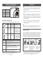
INTRODUCTION
Overview
Congratulations on your purchase of a Home Smart Center. This is a security
control panel which not only functions as a security system, but also monitors
your premises by giving you alert notification when the system is not armed. It
is also a home automation center, which allows you to remotely control house-
hold appliances and lights, even when you are away from home. It can be
controlled by dialing in from any touch tone phone, which makes it even more
convenient and powerful. Additional accessories such as different kinds of
sensors and controllers can be added to suit your specific needs.
This user instructions will guide you through the whole setup procedure as well
as all the programming instructions. Please follow the instructions closely, you
should find it very easy to set up the system.
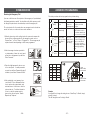
In the package, you should find the following items:
• One Control Panel
• One Motion Sensor (For ML-100A Only)
• Two Door / Window Sensors (For ML-100A Only)
• One Keychain Remote (For ML-100A Only)
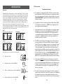
Alert
When Home (System Not Armed)
Beep Beep
Alarm
Not Home (System Armed)
Alarm
Automation
Communicator
ML-001A
FCC Information
Consumer Information:
a) This equipment complies with Part 68 of the FCC rules and the require-
ments adopted by the ACTA. On the bottom
of this equipment is a label
that contains, among other information, a product identifier in the format
US:AAAEQ##TXXXX.
If requested, this number must be provided to the
telephone company.
b) An applicable certification jacks Universal Service Order Codes (USOC)
for the equipment is provided (i.e.,
RJ11C
) in the packaging with each
piece of approved terminal equipment.
c) A plug and jack used to connect this equipment to the premises wiring
and telephone network must comply with the applicable FCC Part 68
rules and requirements adopted by the ACTA. A compliant telephone
cord and modular plug is provided with this product. It is designed to be
connected to a compatible modular jack that is also compliant. See
installation instructions for details.
d) The REN is used to determine the number of devices that may be con-
nected to a telephone line. Excessive RENs on a telephone line may
result in the devices not ringing in response to an incoming call. In most
but not all areas, the sum of RENs should not exceed five (5.0). To be
certain of the number of devices that may be connected to a line, as
determined by the total RENs, contact the local telephone company. [For
products approved after July 23, 2001, the REN for this product is part of
the product identifier that has the format
US:AAAEQ##TXXXX
. The digits
represented by ## are the REN without a decimal point
(e.g
., 03 is a
REN of 0.3). For earlier products, the REN is separately shown on the label.]
e) If this equipment AM-002
causes harm to the telephone network, the
telephone company will notify you in advance that temporary discontinu-
ance of service may be required. But if advance notice isn’t practical, the
telephone company will notify the customer as soon as possible. Also,
you will be advised of your right to file a complaint with the FCC if you
believe it is necessary.
f) The telephone company may make changes in its facilities, equipment,
operations or procedures that could affect the operation of the equipment.
If this happens the telephone company will provide advance notice in
order for you to make necessary modifications to maintain uninterrupted
service.
–53–
PS-101
WD-101
4B-101
Zone 1
Sensor 1
Triggered

INTRODUCTION
–5–
• One AC adapter
• One telephone cord
• Batteries for all sensors (For ML-100A Only)
- 1 PC 9V Alkaline Battery (PS-101)
- 1 PC 12V Alkaline Battery Type 23A
(4B-101 -installed)
- 2 PCS 3V Lithium Battery CR-2032
(WD-101 -installed)
• Rechargeable battery of the Control Panel:
North American version
European Version
• Mounting hardware
Basic installation involves the following procedures:
1. Install Control Panel ML-001A
2. Program Passwords
3. Program Phone Numbers
4. Install Door / Window Sensors WD-101 (For ML-100A Only)
5. Install Motion Sensor PS-101 (For ML-100A Only)
Master Password ____________________
Secondary Password ____________________
Duress Password ____________________
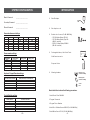
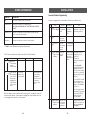
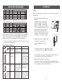
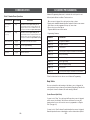
ZONE SENSOR 1 SENSOR 2 BEEP / ALARM AUTO MUTE EVENT TRIGGER ALERT
Example
Front Door Front Window Beep / Alarm Y / N Disabled / On / Off Y / N
1
2
3
4
5
Sensor locations and settings
Phone number settings
PHONE MEMORY PHONE NUMBER REDIAL COUNT REPEAT COUNT
Example
321-123-4567 5 5
1
2
3
4
5
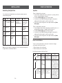
Keychain / Keypad Remotes settings
KEYCHAIN / KEYPAD LOCATIONS OWNER (KEYCHAIN) / LOCATION (KEYPAD)
Example
Keychain Owner - John
6
7
8
9
0
Control Modules settings
CONTROL MODULES LOCATIONS / APPLIANCES
Example
Family room lighting
6
7
8
9
0
SYSTEM CONFIGURATION
–52–
Mounting Plate
(For ML-100A Only)
Ball-head joint
(For ML-100A Only)
Screws
Pack

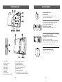
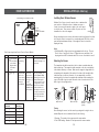
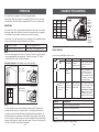
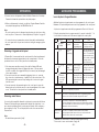
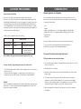
INTRODUCTION
]
14
15
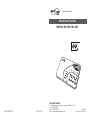
1. Zone LEDs
2. Numeric Keypad
3. Arm button
4. Status button
5. Mute button
6. Panic button
7. Power LED
8. Arm LED
9. Program LED
10. System Low Battery LED
11. Built-in Siren and Speaker
12. Programming button
13. Buzzer Mode Selector
14. Phone Jack for external phone
15. Line Jack for telephone line
16. Adapter socket
17. Battery Compartment
18. Language Selector (only available for
models support multiple languages)
–6–
16
17
7
11
8
1
2
4
18
13
12
Control Module SW-100
(US and Canada)
- To turn home appliances / lights on / off
- Max rating: 960W (Resistive)
Control Module SW-101U (UK), SW-101F
(French), SW-101G (German)
(3 models for 3 countries)
- To turn home appliances / lights on / off
Emergency Dialer (AD-433S)
- External dialer with user programmable voice
message
- Calls up to 9 phone numbers
- One personal voice recording up to 40 seconds
- Can be installed anywhere within 100 feet from
the control panel, with a phone socket
Swing door opener (DM-100)
- Remotely open / close a swing door
- Fits most interior doors
ACCESSORIES
905-608-9223
AD-433
®
–51–
10
3
5
6
9
4

–7–
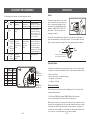
INSTALLATION
Installing the Console
It is important determine where the control panel will be located. Please follow
the criteria below to select the ideal location for the control panel.
- Place it where electrical outlet and phone line can be accessed
- Place it where it is easily accessible by the users
- Place it away from any doors or windows which could be accessed by
non-intended users
- Place is away from extreme temperature sources such as oven, stove
and away from large metal objects which could affect the wireless
performance
After a location has been selected, you may begin the installation and connect all
the necessary wires and power up the unit.
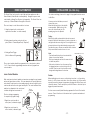
1. Undo the 2 screws on the battery cover.
2. For models support multiple languages,
select the desired language based on
the setting below:
1. German
2. Spanish
3. French
4. English
3. Connect the power adapter to the
socket inside the battery compart-
ment. The power adapter should
be connected to an AC electrical
outlet. You should see all LEDs
turn on, LO BATT LED should be
off.
Language
selector
ACCESSORIES
Audio Sensor (AS-101)
- When audio level exceeds preset limit, it will trigger the
alarm
- Place beside smoke detector, CO detector, so when these
detectors are triggered, the control panel will be triggered
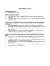
Remote Control (4B-101)
- Additional keychain remotes for other family members
- To arm, disarm or trigger the panic alarm with this remote
Keypad Control (KP-434)
- External keypad control
- To arm, disarm or trigger the the panic alarm with this
remote
- Ideal mounting locations include upper floor, backdoor, or
garage
Wrist Watch Style Panic Remote (HW-101)
- Activate the panic alarm instantly with this remote
- Wear it as a watch
- Splashproof design, can be worn during showering
Panic Transmitter (PT-101)
- Activate the panic alarm instantly with this remote
- Wear it as a pendant
- Splashproof design, can be worn during showering
Audio Alarm (AA-433)
- External Siren
- Powered by AC adapter with backup battery
®
A
A
-
4
3
3
®
–50–

–8–
INSTALLATION
5. After inserting the rechargeable battery, the LO
BATT LED will be off if the battery is fully
charged, otherwise it will be on.
6. Connect the phone line from the wall socket to
the “LINE” socket inside the battery
compartment.
7. [OPTIONAL] If another telephone that will be
using the same telephone jack, you may
connect this telephone to “PHONE” outlet of the
control panel by a phone cord (not provided).
8. The phone line(s), cord of the power adapter
should all come out from the lower right corner
of the control panel in order to close the battery
cover properly.
9. The battery cover can now be closed, and tighten
the 2 screws to secure the battery cover.
PWR, ARM, PROG LEDs should be flashing,
zone LEDs should be off.
4. Insert the rechargeable battery to the battery compartment. There are 2
different types of rechargeable battery for 2 markets:
a.
North American Version: Lead Acid
Connect the 2 wires to the battery. Red wire
connects to the “+” terminal on the battery.
Black wire connects to the “-” terminal on the
battery. Markings on the battery should face up.
b. European Version: Ni-MH
Plug in the wire from the battery to the battery
socket inside the battery compartment.
7-1/8"
10. The control panel is intended to be mounted on a
flat wall. 2 screws are required to mount the
control panel securely on the wall. It should not be
mounted too high or too low. In most situations, just
below eye level is ideal.
11. Once you have selected the mounting
location, tighten 2 screws on the wall.
They should be
7-1/8" apart from each other, on the same
horizontal level. Do not tighten the screws
all the way in, leave about 1/8" from the
wall in order for the control panel to be
hanged onto the wall.
(Optional)
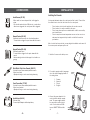
Door/Window Sensor (WD-101)
- Magnetic Contact Sensor
- For all doors or windows
- Batteries included
Repeater (RP-434)
- Extend the operation range between 2 wireless devices,
such as any sensors and control panel
- Doubles the operation range automatically between
sensors and control panel
Water Sensor (FS-101)
- Alerts you when water is detected
- Ideal for water detection in basement, under the sink, even
bathroom
Garage Door Monitor
TM
Sensor (GS-101)
(Available in US and Canada)
- Monitors your garage door
- Alerts you when the garage door is left open
Garage Door Monitor
TM
Sensor (GS-102)
(Available outside US and Canada)
- Monitors your garage door
- Alerts you when the garage door is left open
Indoor/Outdoor Motion Sensor (PS-101)
- Monitors area in a 110 degree ARC and up to 40 feet away
from the sensor
ACCESSORIES
Additional sensors and transmitters as well as add on accessories are available
to work with your system.
TM
–49–

Enter master 3 beeps for valid
password to password. 1 long
programming mode beep for invalid
password.
[1] - Master password
[2] - Secondary password
[3] - Duress password
Select any 4-digit pass-
word, each digit can be
from 0 to 9
Enter the new password 3 beeps if new pass-
again for confirmation word is accepted. You
will hear [Password
Accepted]
Programming Passwords
Master Password can be used for programming, arming, disarming the
system, and telephone access. The default Master Password is [1234].
Secondary Password can be used for arming, disarming the system, and
telephone access. Secondary Password cannot be used for programming.
The default Secondary Password is [0000].
Duress Password is used when you are forcibly compelled to disarm the
control panel. Entering the duress password will stop the siren from sounding
but the control panel will silently call the emergency phone numbers for help.
The default Duress Password is [3838]. You should definitely change this
password and let all the users know this password.
Changing Passwords
It is strongly recommended to change all 3 passwords when you first set
up the system.
In order to change the password, follow the procedures below.
INSTALLATION
[PROG]
[MPIN]
[2]
[1] or
[2] or
[3]
[new
4-digit
password]
[new
4-digit
password]
Enter
Programming
mode
Select
password
programming
Select which
password to
change
Enter new
password
Enter new
password to
confirm
1
2
3
4
5
–9–
Step Keys Function Description Note
After mounting the door sensor, it - Please ensure the magnet is aligned with
doesn’t work anymore. the red marking on the transmitter.
- If you are mounting the sensor on to a
metal door or window, a spacer may be
required to avoid magnetic interference
caused by the metal door / window.
- Make sure the sensor is within the operation
range of the control panel by bringing it
closer to the control panel.
My motion sensor is not very The motion sensor is designed to detect the
responsive, sometimes when I walk “First Motion”. First Motion means no motion
by it, the control panel doesn’t respond, is detected within the past 20 seconds,
but sometimes it does. and if a motion is then detected, that is the
“First Motion”. So if you continue to walk
in front of the motion sensor, it will only
pick up the first motion. Unless you wait
for 20 seconds, then walk again, the control
panel will respond. Otherwise, the control
will only respond to the first motion.
TROUBLE SHOOTING
When a sensor is triggered, the - Make sure the battery in the sensor is
control panel doesn’t respond at all, installed properly, pay attention to the
what is the problem? polarity.
- Make sure the sensor is learned to the
control panel. Follow instructions on
page 37 on how to learn a sensor.
- You may try to bring the sensor closer to
the control panel, ensure it is not out of
the operation range.
My motion sensor sometimes gets Ensure the motion sensor is not facing
triggered by itself, how can I prevent direct sunlight, nor any A/C or furnace
that? vents. You may also reduce the sensitivity
to low. If your motion sensor is located
outdoors, you may want to relocate it.
Sensors
–48–

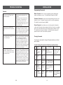
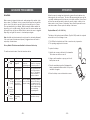
Phone Number Programming
You can program up to 6 Emergency Phone Numbers. When the system is in panic,
the control panel will call these phone numbers and announce its status.
The 6 emergency phone numbers include:
- 5 voice message phone numbers
- 1 Contact ID message phone number
Program the following for Voice Message Phone Numbers
- Phone memory (from 1 to 5), this is where the phone numbers will be stored
- Phone number, up to 29 digits.
- Redial count, this is how many times that phone number will be called, from 1
to 9 times.
- Repeat count, this is how many times the emergency message will be repeated,
from 1 to 9 times.
**Note:
You may enter a 3-second pause between digits by pressing [Mute] if needed.
You may also enter consecutive multiple pause periods. For example, you may
enter a phone number: (123)-456-7890 [Mute] 1234. After the phone number
(123)-456-7890 is dialed, it will wait for 3 seconds, then dial 1234, which can be
a password to a paging system, or an access code for a phone dialing system.
–10–
INSTALLATION
You will hear [Enter
Redial].
You will hear [Enter
Repeat].
3 beeps for valid
password. 1 long beep
for invalid password.
During emergency, phone
memory 1 will be called first,
then phone memory 2, 3, 4, and
5. So phone memory 1 has
higher priority.
You will hear [Enter
phone memory].
You will hear [Phone
Accepted] indicating the
phone number and its
settings have been
programmed successfully.
Repeat is the number of times
that voice emergency message
will be played, from 1 to 9 times.
It is recommended to set up
the repeat time to 5 or more.
Redial is the number of times
that phone number will be
called. Each phone number
can have a different redial
count, from 1 to 9 times.
Phone number can be up to 29
digits.**
Enter master password to
programming mode
[1] to [9]
+ [Arm]
[1] to [9]
+ [Arm]
[1]
[1] to [5]
[PROG]
[MPIN]
[Phone
number]
+ [Arm]
Enter Repeat
count
Enter Redial
count
Enter
Programming
mode
Select phone
number
programming
Enter phone
number
Enter phone
memory
1
2
3
4
5
6
Step Keys Function Description Note
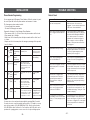
Questions Solutions
Why I can’t arm my system? Make sure none of the sensors are
triggered. You can check this by the zone
LEDs, none of them should blink.
I cannot arm the system even when no You need to disarm the system again by
sensor is triggered, and the ARM LED either entering the password or disarm by
is off. keychain remote. Although the ARM LED
is off, but the system is not completely
disarmed after an alarm was triggered.
Refer to page 22 on how to completely
disarm a control panel after an alarm has
been triggered.
Why the ARM LED keeps flashing? That means you have not programmed any
emergency phone numbers. For instructions
on how to program emergency phone
numbers, please see page 10.
How do I exit programming mode You can press the programming button on
when I’m in the middle of it? the side of the unit to quit programming
anytime.
When a sensor is triggered, the alarm You have programmed that sensor in alarm
sounds instantly even it is not armed, mode, instead of beep mode. Please refer
why is that? to page 29 for instructions of how to program
it back to beep mode.
When the alarm is triggered, why The control panel will stop calling when it
the control panel won’t call all the is disarmed by any one of the recipients.
programmed phone numbers? It Disarm can also be done locally thru the
always stops before calling the keypad on the control panel by entering a
last number. valid password.
Why the control panel doesn’t beep You have placed the buzzer mode selector
when a sensor is triggered, while on the side of the control panel to “II”, this
only the zone LED flashes? will disable the beeping. Placing it to “I” will
enable the beeping.
The control panel is in armed mode, If the triggered sensor is programmed in the
why activating a sensor will not cause Alert Zone (Bypass Zone), alarm will not
an alarm, or call any emergency phone sound, and emergency call will not be made
number? if this sensor is triggered. The control panel
will only respond when it is disarmed, in
alert mode.
TROUBLE SHOOTING
Control Panel
–47–

Note:
- It’s not recommended to program 911, fire station or any emergency services
phone numbers into any of the phone memories without their approvals.
- Ensure to program a valid phone number and write down the programmed
phone number on the System Setting Information provide on the back of this
user's instructions.
- You may quit programming by pressing [PROG] button at any time.
- If no phone number is programmed, the ARM LED will continue to flash.
Testing Phone Numbers:
After you have programmed all the phone numbers, you should verify you have
programmed the phone numbers correctly. This can be done by triggering the
alarm silently by entering the duress password, so it dials to the programmed
phone numbers without sounding the alarm.
Note:
You must inform the recipients of the programmed phone numbers, so they know
what to expect when they receive the phone call from the control panel during an
emergency. These recipients should know the password to your control panel if
you expect them to have remote access of your control panel. For more informa-
tion regarding receiving the emergency call, please refer to page 26.
1. Press [Arm], you should hear beeping from the control panel.
2. Press [3838]. Beeping will stop, and the control panel will start to dial the first number.
3. The called party should receive the call. Pick up the call and say “Hello”, an
emergency message “System Panic” will be played. If the programmed phone
doesn’t ring, ensure the phone number is programmed correctly, or reprogram
this phone number again.
4. After the emergency message has been played for several times (depending on
how many times it was programmed), the called party will hear “Enter Password”.
5. Enter either the master password or secondary password. If the correct
password is accepted, you will hear “Password Accepted”, otherwise, you will
hear “Password Failure”.
6. Press [0][#] on the telephone to hang up.
7. The control panel will start to dial the next programmed phone number.
Note:
- Refer to page 26 [Receiving the Emergency Call] for more info on how to react
to an emergency call.
- The password is treated as a confirmation of the emergency message. Once a
valid password is entered, the control panel will not call that number again, it
will proceed to the next number.
- If any one of the called parties disarms the control panel, the control panel will
not continue to dial the remaining phone numbers.
- After calling all the programmed phone numbers, the control panel will be back
to the previous operation mode.
INSTALLATION
–11–
HOME AUTOMATION
DISABLE EVENT TRIGGER
ENABLE EVENT TRIGGER
This row :
Buttons to Disable Event Tigger
Zone LED : Off
This row :
Buttons to Enable Event Trigger
Zone LED : 1) On (Event Trigger On)
2) Flash (Event Trigger Off)
Press once will enable “Event Trigger On”,
press again will enable “Event Trigger Off”.
This row of buttons operates in toggle manner,
between event trigger on and event trigger off.
Zone 1
Button [1]
Zone 2
Zone 3
Zone 4
Zone 5
Button [2]
Button [3]
Button [4]
Button [5]
Button [6]
Button [7]
Button [8]
Button [9]
Button [0]
®
–46–

–12–
Contact ID Phone number
You can program a telephone number for calling to the central monitoring station.
When the system is in panic, the control panel will call this phone number and
will send out a Contact ID message with event code 140, which represents
“General Alarm”.
Follow the instructions below to program the necessary info in order to call a
monitoring station:
- Phone number of central monitoring station (up to 29 digits)
- Account number given by the Central Monitoring Station
INSTALLATION
Press [PROG]
Press [MPIN]
Enter Program-
ming mode
Press [1]
Enter master
password to
programming mode
3 beeps for valid
password. 1 long
beep for invalid
password.
You will hear
[Enter Phone
Memory]
Select phone
number
programming
Press [0]
You will hear
[Phone Zero]
Enter phone
memory
During emergency,
the Contact ID phone
number has the highest
priority, it will be the
first number to call.
Enter [Phone
number] +
[Arm]
You will hear
[Phone Accepted]
indicating the phone
number has been
programmed
successfully.
Enter phone
number
Phone number
can be up to 29
digits.
Step Keys Function Description Note
4
3
2
1
Phone Number Programming (Calling to Central Monitoring Station)
HOME AUTOMATION
Event Trigger
You can control up to 5 different devices not only manually, but also automatically. It is
called Event Trigger. That means when a sensor is triggered, the control panel will
transmit a signal to activate the designated control module. Applications include:
- Lights on when you open the front door
(walking into a room, lights on automatically),
this is called "Event Trigger on".
- Lights off when you open a door. (walk away
from a room, turns lights off), this is called
"Event Triggered off".
Event trigger is only applicable to the sensor(s)
and control module in the same zone. For
example, you can program control module 1 to
be on or off when zone 1 sensor(s) is triggered.
You can also program control module 2 to be
on / off when zone 2 sensor(s) is triggered.
Factory Default: This feature is disabled for
all zones at the factory.
To change the event trigger setting follow the instructions below.
Event Trigger On
Event Trigger Off
1
2
3
4
[PROG]
[MPIN]
Enter Program-
ming mode
Enter master
password to
programming
mode
3 beeps for valid
password. 1 long beep
for invalid password.
[7]
Select Event
Trigger
After [7] is entered,
some zone LEDs will be
off, on or flash. This
indicates the setting of
event trigger.
Disable Event
Trigger: [1] to
[5]
Enable Event
Trigger: [6] to
[0].
Select which
zone you would
like to enable /
disable event
trigger.
Refer to the
diagram below
to select the
appropriate
setting.
If event trigger “ON” is
enabled, that zone LED will
be on. If event trigger “OFF”
is enabled, that zone LED
will flash. If it is disabled, the
zone LED will be off. You are
allowed to make multiple
changes before terminating
programming mode.
[PROG]
when
finished.
Terminate
programming
mode.
PROG LED
will be off.
Step Keys Function Description Note
–45–

–13–
INSTALLATION
Account Number Programming
In order to program the account number, follow the procedures follow:
Press [PROG]
Press [MPIN]
Enter
Programming
mode
Press [2]
Enter master
password to
programming
mode
3 beeps for valid
password. 1 long beep
for invalid password.
Select
password
programming
Press [0]
Select to
add / change
account
number
[0] = Add/change
account number
Step Keys Function Description Note
4
3
2
1
Enter [New 4-
digit Account
Number]
This number can be a
combination of 0-9,
B,C,D,E & F.
To enter 0-9:
Enter by the keypad 0-9
directly.
To enter B,C,D,E,F:
Press [STATUS] and the
ARM light will stay on.
Then press the following
keys for the correspond-
ing letters (1=B, 2=C, 3=D,
4=E, 5=F).
Press [STATUS] to return
back to number-mode
when you want to input
numbers. The ARM light
will turn off.
You can toggle between
the number or letter mode
by pressing [STATUS]
when entering the
account number.
Enter the 4-digit
account number
given by the
central monitoring
station.
Enter new
account
number
Enter [New 4-
digit Account
Number]
5
3 beeps if new account
number is accepted. You
will hear [Password
Accepted]
Enter the new
account num-
ber again for
confirmation
HOME AUTOMATION
Part 2 Erase communication from Control Panel to Control Module
ZONE LED DESCRIPTION
Off Zone is not occupied by any control module
Flashes twice That means a remote has occupied that zone.
THIS IS NOT A CONTROL MODULE, THEREFORE, SHOULD NOT BE
ERASED.
Flashes once That zone is occupied by a control module. You may select this
zone to erase this control module.
Flashes once, That means this zone is occupied by a remote AND a control module.
then twice You may select this zone to erase the control module.
** Table F: Zone LED status for erasing control module.
1
2 To erase the
memory of the
control module
Control module LED
will flash rapidly
indicating all the
memory is erased.
You may now
release the learn
button.
Remove the
control module
from the
electrical outlet
Press and hold
the learn button
on the control
module while
plugging in the
control module
to an electrical
outlet.
Once the memory of the control module is erased, all of its memory is cleared. If
you have other remotes / control panels controlling this control module, you need
to re-program those remotes / control panels.
Step Keys Function Description Note
–44–

–14–
INSTALLATION
Deactivating the Digital Dialer
You can deactivate the digital dialer by erase the phone number memory for
central monitoring station.
Press [PROG]
Press [MPIN]
Enter Program-
ming mode
Press [1]
Enter master
password to
programming mode
3 beeps for valid
password. 1 long
beep for invalid
password.
You will hear:
[Enter Phone
Memory]
Select phone
number
programming
Press [0]
Enter phone
memory
Step Keys Function Description Note
4
3
2
1
Press [ARM]
You will hear
[Phone Zero
Empty Memory]
indicating the phone
number have been
deleted, the digital
dialer is deactivated.
Confirm delete
the phone
number.
Note: If no phone number is programmed to call the central monitoring station,
the digital dialer is automatically disabled.
HOME AUTOMATION
Erase Control Modules
To erase a control module from the control panel, it is similar to learning a
control module, which involves 2 parts.
1. Erase the memory of the control panel
2. Erase the memory of the control module
Part 1 Erase the memory of the Control Panel
1
2
3
[PROG]
[MPIN]
Enter
Programming
mode
Enter master
password to
programming mode
3 beeps for valid
password. 1 long beep
for invalid password.
[0]
Select erase
control
module
programming
After [0] is entered, some
zone LEDs will flash or
stay off. The zone LEDs
represent whether that zone
is occupied by any control
module. **See Table F
Select the
control module
location you
would like to
erase
Refer to the table
below to select
the control
module location.
After you have selected the
remote location, you will
hear 3 beeps and verbal
confirmation [Device X
Empty Memory], where
X is the control module
location you have selected.
To erase an
occupied
control module,
press [1] to [5].
To turn off a light with the control panel:
1. Press the device number button on the control panel, i.e. pressing 1 will turn
off device 1, pressing 2 will turn off device 2.
2. You will hear [Device X Off], where X is the device number.
3. You will also see the PROG LED flashing, indicating the control panel is
sending out the wireless signal to control the specific device.
4. If the receiver receives the signal, the control panel will announce [Device
Off Accepted].
To turn on a light with the control panel:
1. Press the number below the device number that you would like to turn on, i.e.
pressing 6 will turn on device 1, pressing 7 will turn on device 2.
2. You will hear [Device X On], where X is the device number.
3. You will also see the PROG LED flashing, indicating the control panel is
sending out the wireless signal to control the specific device.
4. If the receiver receives the signal, the control panel will announce [Device
On Accepted].
Operation
Step Keys Function Description Note
–43–

Part 2 Learn signal from Control Panel to Control Module
HOME AUTOMATION
Control Module [1] is represented by zone LED 1
CONTROL MODULE
LOCATION
16
27
38
49
50
TRANSMIT
BUTTON [X]
1
2
Enter
Programming
mode
LED on the Control Module
will flash indicating it is in
learn mode.
[6] to [0]
Transmit an ON
signal for the
selected device
from the Control
Panel to the
Control Module.
Refer to the
chart below to
determine which
button [6] to [0]
to press.
You should
transmit the “ON”
command for the
selected device.
After [X] is entered, you
will hear [Device X On]
indicating you have trans-
mitted an ON signal for
device X, where X is the
Control Module Location.
The LED on the Control
Module should be off,
indicating it has learned
the signal, you may now
release the learn button
and the LED will stay on
again.
Press and hold
the learn button
on the Control
Module until its
LED starts to
flash.
Step Keys Function Description Note
This row :
Buttons for
Learning Control Module
–15–
–42–
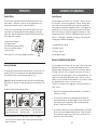
Window / Door Sensor is used to monitor doors or windows that
open and close. When these doors / windows are open or
closed, the sensors will transmit a signal to the control panel
to notify the user. These sensors consist of 2 parts, one is the
transmitter, the other is the magnet.
Before installing the sensor, remove the battery isolator by pulling out the yellow
tab. Once the isolator is removed, the corresponding zone LED on the control
panel will flash and buzzer will beep. If the magnetic contact is closed, the
beeping will stop.
Note:
- Both Window/Door Sensors have been programmed at the factory. They are
Zone 1 Sensor 1 and Zone 2 Sensor 1. Trigger the sensor and listen to the
beeping and zone LED to determine which one is zone 1 and which is zone 2.
Testing:
After mounting the sensor, test the sensor by opening and closing the door or
window. Open the door or window will result in the followng:
1. Beeping - The number of beep represents the zone number.
2. Zone LED flashing - Number of flash represents the sensor number.
Mounting the Sensor
The transmitters should be mounted on the door frame or window frame by
double sided tape. The magnet should be mounted on the door or window by
either double sided tape or screws. Make sure the magnet is aligned with the
red marking on the transmitter. If the surface of the frame is flat enough, double-
sided foam tape is sufficient, otherwise, it is recommended to screw the
mounting plate to the frame, then apply double sided tape. After mounting the
sensor, if the AAA+ logo is inverted, remove the front cover and rotate it so the
AAA+ logo is in the upright position.
INSTALLATION (ML-100A Only)
Installing Door / Window Sensors
Transmitter
Magnet
Double-sided
foam tape
Mounting plate
and screws
(optional)
Sensor
Magnet on the left
Magnet on the right

Part 1 Learn signal from Control Module to Control Panel
HOME AUTOMATION
ZONE LED DESCRIPTION
Off Zone is not occupied by any control module
Flashes once This zone is occupied by another control module. Programming
another remote to this zone will overwrite the previous control
module.
Flashes twice This zone is occupied by a remote. You can still program a control
module to this zone, and it will not overwrite the remote you have
in this zone.
Flashes once, This zone is occupied by a remote AND a control module. If you
then twice program another control module to this zone, it will overwrite the
previous control module, but not the remote.
** Table E: Zone LED status for learning control module.
Activate the
control module
by pressing its
learn button
once quickly.
1
2
3
4
[PROG]
[MPIN]
Enter Program-
ming mode
Enter master
password to
programming
mode
3 beeps for valid
password. 1 long beep
for invalid password.
Select learn
control module
programming
[1] to [5]
After you have selected
the control module location,
that zone LED will be on.
After [4] is entered, some
zone LEDs will flash or
stay off. The zone LEDs
represent whether that
zone is already occupied
by another control
module.**See Table E.
Select control
module location
(Max. 5 control
modules)
Select the
location [1], [2],
[3], [4], or [5].
Send signal
from control
module to
control panel.
Once the signal
is transmitted to
the Control Panel,
that signal will be
stored.
You will hear
[Device X Accepted],
where “X” is the control
module location.
[4]
Step Keys Function Description Note
–16––41–
Note:
- Try to mount the sensors as far away from the floor as possible to avoid
damaging them. Mounting the sensors at a higher position will also result in
better operating range.
- Do not mount the sensor to the exterior of the door / window, always mount the
sensor to the interior side of the door / window to avoid being damaged or
stolen by non-intended users.
INSTALLATION (ML-100A Only)
2 Single flash
1. Beep___Beep___
Beep___Beep___
............
Installing Motion Sensor
Insert Battery
Undo the screw on the back of the motion sensor and
remove the battery cover. Connect a 9V alkaline battery
to the battery connector. Please note the polarity.
If you are planning to install the motion sensor outdoor,
you should reduce the sensitivity by placing the jumper
at location “2”.
For indoor application, if you want to reduce the
sensitivity, you can change the jumper setting to
“2” as well.
The motion sensor is most suitable for guarding a large area such as living room,
family room, or bedroom. It can also be used to monitor a hallway or stairway.
Sensitivity
Caution:
Depending on the environment, if you experience a false trigger when the motion
sensor is placed outdoors, you should relocate it or even place it indoors. Wind
blowing at a tree, or direct sunshine could cause a false trigger. Therefore, if the
location at where the motion sensor is mounted could cause a false trigger, you
should change the mounting location for such sensor.
Jumper Location 1 High Sensitivity
Jumper Location 2 Low Sensitivity

–17–
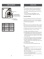
The Control Panel can be used to control lights and home applicances with a
Control Module, (Control Module is sold separately). Garage door opener can be
controlled with a Garage Door Receiver (sold separately). The Control Panel can
control up to 5 Control Modules / Garage Door Receivers.
There are 3 ways to control these modules / receivers:
1. Using the keypad on the control panel to
operate these modules / receivers manually
2. Calling in away from home using a touch tone
phone (Refer to “Remote Operation by Telephone”)
3. Setting up Event Trigger
(Refer to Advanced Programming)
These control modules should be programmed to the control panel as device
1 to 5. Please follow the programming instructions below to program these
control modules.
Learn Control Modules
Both control panel and control module are transceivers, meaning they can transmit
and receive signals from each other. For home automation, the user will initiate an
action from the control panel, such as sending a signal to turn on the light, then the
control module will receive such signal and respond. The control module will then
send back a confirmation to the control panel
to indicate the light has been turned on.
Therefore, during programming,
it is required to program 2 things:
1. Signal from control module to
control panel (confirmation signal)
2. Signal from control panel to
control module (command signal)
HOME AUTOMATION
Door open
Lights
on
–40–
Caution:
When installing the motion sensor, avoid placing it near heat or cold producing
devices (i.e. A/C or furnace vents, fans, ovens, space heaters, etc). Air movement,
especially caused by changes in temperature may trigger the Motion Sensor and
cause false alarms. Please carefully test your Motion Sensor so that it will only be
triggered by wanted movement.
You have now successfully installed and programmed the Control Panel and its
sensors. Please follow the rest of the instructions for operations and advanced
programming.
Testing
Walk test should be performed after the motion sensor is
mounted. Walk in the detected area, if motion is detected, a
red light inside the sensor will glow. If the red light does not
glow, motion has not been detected and you may need to
re-position the sensor. Ensure you walk test all the locations
that you would like the motion sensor to cover.
Note:
- Perform the walk test after you have inserted the
battery for more than 1 minute.
- Before performing the walk test, the sensor should
not detect any motion.
- After motion is detected once, the sensor will not
be triggered unless no motion is detected for 20
seconds. Therefore, wait for at least 20 seconds
during walk testing between 2 activations.
INSTALLATION (ML-100A Only)
You may now close the battery cover and
re-insert the screw.
Mount the ball-head joint on the wall with
screws provided. Slide the back of the
sensor into the ball-head joint. The
mounting angle can be adjusted.
For outdoor monitoring, please refer to page 33 to program the motion sensor
to Alert Zone.
M
01234567 8910111213
2
4
6
8
10
12
14
DETECTING AREA: (Unit = meter
)
55°
22°
22°
12°
SENS OR
27°
55°
1.2M
11°
®
1
1
6
2
2
7
3
3
8
4
4
9
5
5
0
ARM
STATUS
MUTE
PWR
ARM
PROG
LOBATT
LO
BATT
Turn on
(command
signal)
Confirm on
(confirmation
signal)
Control
Panel
Control
Module

Note:
- Each zone can program up to 2 sensors. There are 5 zones, so up to 10 sensors
can be programmed to the control panel. Please refer to page 37, "Sensor
Location Selection Guide" for detail information.
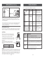
Alert Mode Examples (Door/Window sensor sold separately)
Note:
-For Door / Window sensor, alert notification (beeping and LED flashing) will
continue until the sensor is in closed position, i.e. closing the window or door.
-For motion sensor, the alert notification was disabled at the factory default. To
perform the walk test, it requires to enable the Alert Zone (Bypass Zone) feature
in the Control Panel. After the walk test, it needs to disable this alert zone feature
otherwise it will bypass the signal in the alarm mode. Please refer to the page 33,
"Alert Zone" for detail. Please refer to information.
OPERATION
The Control Panel is always in one of the 2 operating modes:
1. Alert Mode - When the system is not armed (ARM LED off), it is in alert mode.
2. Alarm Mode - When the system is armed (ARM LED on), it is in alarm mode.
The Control Panel will be in alert mode automatically if the system is not armed.
Alert mode allows users inside the premises to know what sensor is triggered.
It is intended to be used when someone stays inside the premises.
In alert mode, the control panel will give you notification of the triggered sensor(s)
by voice announcement, unique beeping and LED flashing.
1 Number of beeps Zone of the triggered sensor
2 Number of flashes of zone LED Sensor number of the triggered sensor
Alert Mode
–18–
ADVANCED PROGRAMMING
Zone 1
SENSOR 1
Button [1]
SENSOR 2
Zone 2
Zone 3
Zone 4
Zone 5
Button [2]
Button [3]
Button [4]
Button [5]
Button [6]
Button [7]
Button [8]
Button [9]
Button [0]
This row :
Buttons for
Sensor 1
Zone LED :
Flash once
This row :
Buttons for
Sensor 2
Zone LED :
Flash twice
Erase Sensors
Proceed to the following to erase a sensor.
1
2
3
[PROG]
[MPIN]
Enter
Programming
mode
Enter master
password to
programming mode
3 beeps for valid password.
1 long beep for invalid
password.
[9]
Select erase
remote
programming
After [9] is entered, some
zone LEDs will flash or
stay off. The zone LEDs
represent whether that zone
is occupied by any sensor.
**See Table D below.
Refer to the table
below to select the
remote location.
Select the
sensor you
would like to
erase
After you have selected the
sensor, you will hear 3 beeps
and verbal confirmation
[Zone X Sensor Y Empty
Memory], where X and Y
are the zone and sensor
numbers you have selected.
To erase an
occupied
sensor, press
[1] to [0].
ZONE LED DESCRIPTION
Off Zone is not occupied by any sensor
Flashes once This zone is occupied by sensor 1.
Flashes twice This zone is occupied by sensor 2.
Flashes once, This zone is occupied by sensors 1 and 2.
then twice
** Table D: Zone LED status for erasing sensors.
Step Keys Function Description Note
–39–
1.
Beep Beep Beep___
Beep Beep Beep___
2. Single flash
1.
Beep___Beep___
Beep___Beep .....
Zone 1 Sensor 1
2. Double flash
Zone 3 Sensor 2 window
open
Page is loading ...
Page is loading ...
Page is loading ...
Page is loading ...
Page is loading ...
Page is loading ...
Page is loading ...
Page is loading ...
Page is loading ...
Page is loading ...
-
 1
1
-
 2
2
-
 3
3
-
 4
4
-
 5
5
-
 6
6
-
 7
7
-
 8
8
-
 9
9
-
 10
10
-
 11
11
-
 12
12
-
 13
13
-
 14
14
-
 15
15
-
 16
16
-
 17
17
-
 18
18
-
 19
19
-
 20
20
-
 21
21
-
 22
22
-
 23
23
-
 24
24
-
 25
25
-
 26
26
-
 27
27
-
 28
28
-
 29
29
-
 30
30


Multi-Link ML-001 User manual
- Category
- Security access control systems
- Type
- User manual
- This manual is also suitable for
Ask a question and I''ll find the answer in the document
Finding information in a document is now easier with AI