Page is loading ...

GENERAL SAFETY INFORMATION
1. Before using the hand tool it is necessary to carefully read this MANUAL.
2. KEEP CHILDREN AWAY FROM PRODUCT USAGE AREA. Do not allow children to handle this product.
3. Always wear ANSI approved safety goggles when working with hand tools.
4. USE THE RIGHT PRODUCT FOR THE RIGHT JOB. There are certain applications for which this product was designed. Do not use this product for a purpose for which it was not intended.
5. NEVER POINT THE LOADED HAND RIVETER AT A PERSON OR ANIMAL.
6. The warnings, cautions and instructions discussed in this manual cannot cover all possible conditions and situations that may occur. It must be understood by the operator that common
sense and cautions are factors which cannot be built into this product, but must be supplied by the operator.
OPERATION
Caution: Always wear eye protection.
Note: Suitable for Aluminium and Stainless steel rivets.
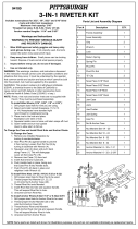
1. Select appropriate rivet for application and drill same size hole through materials to be fastened (fig.1).
2. Select rivet length based on combined thickness of materials to be fastened (fig.1).
3. Turn Riveter to horizontal position allowing the Lever Arm to drop to the fully open position OR move the arm backwards to the fully open position allowing
the rivet to fully insert into the Riveter Nozzle.
4. Apply slight pressure to the Lever Arm to hold the inserted rivet in position, this enables the rivet to be inserted in the inverted position without falling out of
the Riveter.
5. Push the head of the rivet through the hole in the materials, making sure the rivet head comes through both materials being
fastened without being impeded (fig. 3).
6. Compress the Lever Arm and Front Handle together, this will compress and install the rivet.
7. Once the rivet has been installed and the rivet mandrel separates from the rivet head move the Riveter away from the inserted rivet.
8. Release the Riveters Lever Arm while maintaining grip on the Front Handle.
9. The rivet mandrel can be ejected from the Riveter by either flicking the Riveter forward or backwards ejecting the rivet mandrel form the Riveter
depending on preference (fig.4).
Caution: When ejecting the mandrel ensure it is a direction away form the user and by standers.
Replacing The Jaws
1. Close tool handle completely, keeping handle closed with tape or a chain.
2. Remove retaining screw with wrench then remove jaw pusher spring (fig.5).
3. Clean or replace jaws, oiling outside of jaws before reassembly.
4. Reassembly is the reverse of above steps. Be sure that the bevelled end of jaw pusher fits into bevel on the jaws (fig.6).
(fig 3) (fig 4)
Industrial
Mini Hand
Riveter (Semi-Automatic)
CL600
Nose Piece
Riveter Nozzle
Spare Nose Piece
Front Handle
Lever Arm
Hole Diameter
Rivet
Diameter
Combined
Thickness
(fig 2)(fig 1)
(fig 5)
(fig 6 )

8) Spare Parts
For a full list of available spare parts for this item refer to the Kincrome® website www.kincrome.com.au
Type in the part number & click on the documentation tab for a copy of the parts diagram and listing
Warranty given by Kincrome Australia Pty Ltd of 3 Lakeview Drive, Caribbean Park, Scoresby, Victoria (Tel 1300 657 528). The applicable warranty period (12 months) commences on the date that the product
is purchased. If this product has materials or workmanship defects (other than defects caused by abnormal or non warranted use) you can, at your cost, send the product to place of purchase, an authorised
Kincrome service agent or one of Kincromes addresses for repair or replacement. Your rights under this warranty are in addition to any other rights you have under the Australian Consumer Law or other
applicable laws. Our goods come with guarantees that cannot be excluded under the Australian Consumer Law. You are entitled to a replacement or refund for a major failure and compensation for any other
reasonably foreseeable loss or damage. You are also entitled to have the goods repaired or replaced if the goods fail to be of acceptable quality and the failure does not amount to a major failure. For further
details please visit www.kincrome.com.au or call us. Due to minor changes in design or manufacture, the product you purchase may sometimes differ from the one shown on the packaging.
No. Part No. DESCRIPTION
1 CL600-1 NOZZLE PACK (2.4 3.2 4.0)
2 CL600-2 JAW CASE
3 CL600-3 JAWS
4 CL600-4 JAW PUSHER
5 CL600-5 SPRING
6 CL600-6 RETAINER NUT
7 CL600-7 PIVOT PIN KIT
8 CL600-8 DAMPER
9 CL600-9 SPANNER
10 CL600-10 GRIP SET
1
9
2
3
4
5
6
7
10
8
Office Contact Details:
Phone: 1300 657 528
Fax: 1300 556 005
Email: [email protected]om.au
Website: www.kincrome.com.au
/