Page is loading ...


VANNER I NCOR POR ATED Bravo 1800 – Owner’s Manual
ii
VANNER INCORPORATED
Corporate Office:
4282 Reynolds Drive Hilliard, Ohio 43026
Tel (614) 771-2718 Fax (614)771-4904
1-800- AC POWER
BRAVO 1800- OWNER’S MANUAL 9/00 ©Copyright 2000, Vanner, Inc.
OM/D96523 REV.D. 01/2018

VAN N E R I NCOR POR ATED Bravo 1800 – Owner’s Manual
iii
Table of Contents
Section 1 Introduction .................................................................................................................... 1
Section 2 System Operation
Section 2A Product Variations ............................................................................... 1
Section 2B Control Panel ........................................................................... 2
Section 2C Wiring Panel ............................................................................................. 6
Section 2D Theory of Operation................................................................. 7
Section 2E Inverter Sizing.......................................................................... 8
Section 2F Battery Charger Option.......................................................................... 9
Section 2G Automatic AC Power Transfer .......................................................... 10
Section 3
Installation
Section 3A Unpacking the Inverter ....................................................................... 11
Section 3B Inverter Installation Considerations.................................................. 11
Section 3C Remote Panels....................................................................... 14
Section 3D System Start-up and Testing ............................................................. 15
Section 4 System Design Considerations
Section 4A Inverter System Design Considerations ......................................... 16
Section 4B Battery Types and Ratings .................................................................. 17
Section 4C Sizing the Inverter Battery ................................................................. 18
Section 4D DC Charging Systems ......................................................................... 19
Section 4E Inverter Applications .............................................................................20
Section 5 Bravo 1800 Specifications ............................................................................................21
Section 6 Maintenance & Troubleshooting
Section 6A Preventive Maintenance.......................................................................22
Section 6B Maintenance Items ................................................................. 22
Section 6C Troubleshooting Procedures ................................................................23
Section 7 GFCI Test Record……………………………………………………………..24
Section 8 Warranty.................................................................................................25

VAN N E R I NCOR POR ATED Bravo 1800 – Owner’s Manual
iv
List of Figures and Tables
Section 2
System Operation
Figure 1
Bravo 1800 inverter/Charger Illustration ................................................
1
Table 1
Bravo 1800 Product Models ........................................................
2
Table 2
Bravo 1800 Accessories .................................................................................
2
Figure 2
Control Panel ..................................................................................
2
Table 3
LED Status Indicators ...................................................................
5
Figure 3
Wiring Panel...................................................................................
6
Figure 4
Battery Charging Graph................................................................
9
Figure 5
AC Transfer Switch.......................................................................
11
Section 4
Installation
Table 4
DC Cable Size Chart ...................................................................
12
Table 5
DC Fuse Size Chart ......................................................................
12
Table 6
Ground Fault Current Interrupter
GFCI Recommendations ...........................................................
13
Section 5
Figure 6
Dimensional Drawings .................................................................
22
Icon Legend
N
Note
Important
Information
Warning
Failure to observe
Warning could
cause damage to
equipment and
harm personnel

VAN N E R I NCOR POR ATED Bravo 1800 – Owner’s Manual
1
Section 1: Introduction
Thank you for purchasing a Vanner inverter system. We are confident that you will be satisfied
with its performance and its many features. With proper installation and care, you can look
forward to years of service from this high performance product.
This document will describe the operation, technical specifications and installation procedures of
the various models and accessories offered in this inverter product line. We suggest that you
familiarize yourself with the model numbers of the inverter and optional accessories you have
purchased before proceeding with this manual. If you require additional information please
contact your dealer, or contact us directly at the location shown on this inside over of this
manual.
Section 2: System Operation
2A)
Product Variations
We have designed the Bravo 1800 inverter product line to meet the requirements of a variety of
applications. In order to meet these requirements, we offer different models based upon the
following variations:
Inverter-only or Inverter with Battery Charger and AC Transfer Switch
12 Volt or 24 Volt DC Input
120 Volt/60 Hz or 230 Volt/50 Hz Output Power
Wall Mount or Shelf Mount Enclosure
Hardwired AC output or CFGI Duplex Receptacle
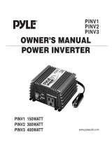
FIGURE 1—Bravo 1800 Inverter/Charger Illustration
Bravo Model BRC12-1800511
(ShelfMount Enclosure)
Bravo Model BRC12-1800WH
with "Drip Shleld/Handle" option
(Wall Mount Enclosure)

VAN N E R I NCOR POR ATED Bravo 1800 – Owner’s Manual
2
2B) Control Panel
General Description
The Control Panel contains LED (light emitting diode) indicators and switches that
you will need to use when installing and operating your inverter system.

VAN N E R I NCOR POR ATED Bravo 1800 – Owner’s Manual
3
System On/Off Switch
The On/Off Switch allows you to control the operation of the inverter and battery
charger. Please note that this switch does not disconnect power from the inverter
system. It sends a signal to the system's electronics to control the inverter.
Note— The ON/OFF switch only controls the inverter portion of the system. On
Inverter/Charger system the battery charger portion of the system is always on when AC
input power it present.
In the On position, with shore/utility power present, the battery charger will
automatically charge and/or maintain the charge on your battery while passing the
shore/utility power through the AC transfer switch to power the AC loads
connected to the system. When shore/utility power is removed the AC transfer switch
quickly connects the AC loads to the inverter, which will obtain its power from the
battery to power the loads.
WARNING
To ensure complete
isolation from
external power use a
remote disconnect
switch in the DC and
AC input circuits
Programming Switch
The Programming Switch is a dip type switch containing three individual slide switches. By placing the switch in the
upper or lower position you select the desired function. Note: On inverter-only models (models without battery charger)
only the Load Demand switch is used.
Programming Switch Positions:
Batt. Type : Lower position = Flooded (wet) lead acid battery type.
Upper position = Gel lead acid battery type.
Load Demand: Lower position = Load Demand disabled/Off.
Upper position = Load Demand Enabled/Automatic.
Charger Output: Lower position = High output (80 amp on 12 Vdc models or 40amps on 24 Vdc models).
Upper position = Low output (40 amps on 12 Vdc models and 20 amps on 24 Vdc models).
Load Demand
The inverter also has an energy-saving feature called load demand." With this feature, the inverter output is pulsed,
significantly reducing the current draw from the battery until a demand is made
on
its output. Continuous output of 120
VAC resumes when an AC load greater than 5 watts is applied. Load demand can be disabled with the Setup switch on
the front panel.
Protective Interlocks
Battery Low:
Over Temperature:
Over Load:
The inverter continually monitors the DC input voltage to ensure that the battery
contains sufficient charge to supply power to the inverter. In the event that the
battery voltage drops to 10.5 (21) volts, an indication of a low charge in the battery,
the inverter will shut off, and the Low Battery indicator will blink. The Low Battery
indicator will illuminate steady when the battery voltage drops near the shut-off
voltage to provide an "early warning" prior to shutting down.
The inverter will shut off if internal temperature sensors detect a high temperature
condition that would damage the inverter.
If a short circuit or a very large load is applied to the inverter's output the
inverter will shut down and the Over Load indicator will illuminate.

VAN N E R I NCOR POR ATED Bravo 1800 – Owner’s Manual
4
LED Indicators
A set of LED (Light Emitting Diode) indicators are provided to display the status of the inverter system. Six LEDs are
provided on inverter/charger models and four are provided on inverter-only models. Table 3—LED Status Indicators
describes the LEDs and their functions.
Remote Monitor Control Panel
The optional Remote Monitor/Control Panel allows the inverter to be monitored from a remote location (within 20'). The
panel contains three status LED indicators. A 20 foot cable is supplied with each remote panel.

VAN N E R I NCOR POR ATED Bravo 1800 – Owner’s Manual
5
Remote Panel –P/N DO5039
Inverter
Light Action
Description
Steady Green Light
Inverter is On
Slow Blinking Green Light
Inverter circuit is Off. Shore power is supplying AC power to loads. The Inverter
will restart when shore Power input is removed.
Fast Blinking Green Light
Inverter is in "sleep mode". Shore Power is Off.
Green Light Off
Inverter is Off. If one of the two charger lights is On or blinking, then Shore Power
is on and supplying AC to the load.
(Sleep Mode—Requires a minimum 5 watt load to activate inverter AC output)
Battery
Low
Light Action
Description
Solid red
Low Battery warning light. Inverter is On.
Blinking Red
Battery has decayed to 10.5 (or 21.0) volts DC causing inverter shutdown. Battery
must be recharged. Then, Inverter on/off switch must be reset to activate.
Overtemp
Light Action
Description
Solid Red
Inverter has shutdown due to over temperature. Shutdown may be caused by high
ambient temperature or restricted cooling air flow to inverter. Shutdown sensor
will auto reset when unit has cooled.
Overload
Light Action
Description
Blinking Red
The inverter is On and warning of pending overload shutdown. Reduce
the AC load quickly or inverter will shut off due to the overload condition.
Solid Red
The inverter is Off. Shutdown was caused by overload. Remove the load and cycle
the inverter On/Off switch to reset to the inverter.
Charger
Bulk
Light Action
Description
Blinking Yellow
Charger is On. Battery is low and being charged at full current output or at o
limited rote as selected on the charger output switch. Current output will remain
at a constant level until battery voltage reaches bulk voltage setpoint. Then,
charger remains in Absorption stage (constant voltage-reducing current for a
timed period before reducing to float stage).
Charger
Float
Light Action
Description
Solid Green
Charger is on.Battery is close to full charge. Charger output voltage is reduced to a
preset maintenance level and current is limited to a rate slected on the charger
output switch.
Table 3-LED Status Indicators

VAN N E R I NCOR POR ATED Bravo 1800 – Owner’s Manual
6
2C) Wiring Panel
General Description
The wiring Panel where all field wiring is connected to the inverter. For wall mounted
enclosures this panel is located on the inverter's bottom surface. For surface mounted
enclosures the wiring panel is on the front, perpendicular to the mounting surface.
AC Output
This circuit breaker provides over-current protection in the AC output circuit.
FIGURE 3—Wiring Panel
INVERTER WIRING PANEL INVERTER/CHARGER WIRING PANEL
INV/CHINV/CHGR
This circuit breaker provides over current protection in the AC Input circuit to the charger and the
AC output of the inverter, depending on which mode the unit is in.
DC (Battery) Input
A DC wiring enclosure is located behind the wiring panel and contains terminals to connect the
two cables from the battery. Cable damps are provided to secure the cables after they are
terminated in the wiring enclosure. A removable cover allows access to the wiring enclosure.
AC Input & Output
An AC wiring box is located behind the wiring panel to connect the field wires to the wires
that are provided inside the wiring box. One cable clamp is provided for the AC input, and
one cable clamp (or GFCI receptacle) for the AC output.
There is no AC input cable damp on non-charger models having GFCI receptacles.
Remote Panel
This six-wire RJ11 modular jack is provided for the optional Monitor/Control remote
panel.

VAN N E R I NCOR POR ATED Bravo 1800 – Owner’s Manual
7
2D) Theory of Operation
Inverter Overview
In general, an inverter converts DC electrical power into AC power. This power can be
used to operate various AC driven appliances.
The most common battery systems are 12 or 24 volt. Some systems, however, operate on
higher voltages such as 32, 36, 48, or 120 volts. The most common inverter AC output
power is 120 volts at a frequency of 60 Hz, although some inverters are designed to produce
240 volts, or both 120 and 240 volts at 60 Hz. Because some countries use power of
different voltage and frequency (e.g. 230 volts at 50 Hz), inverters are available to conform
to these requirements.
Inverters use electronic circuits to switch DC input power at the required frequency, such as
60 Hz. This "switched" DC resembles AC power, and is then stepped up in voltage through a
transformer. The result is a modified sine wave AC output of the required voltage and
frequency that can power AC-driven equipment.
Inverter Types
The three available inverter types are distinguished by the type of AC output wave form
they produce. This wave form affects the AC loads they operate. This section provides an
overview of these inverter types, including the advantages and disadvantages associated
with using each type.
Sine Wave Inverter
Sine wave inverters produce an AC output wave form like power produced by the electric
utility companies and rotating generators. The sine wave inverter's wave form is
characterized by the highest peak voltage and smooth voltage transitions (no steps or square
wave components). Such inverters are the most costly of the three inverter types because
they contain additional electronics to produce the required wave form.
Modified Sine Wave Inverter
Modified sine wave inverters are sometimes called "quasi sine wave inverters" or "modified
square wave inverters."
Modified sine wave inverters generally cost more than square wave inverters because they contain
additional electronic circuitry to produce True RMS regulated AC output. Modified sine wave
inverters have higher AC peak voltages than square wave inverters, and automatically control the
width of the AC output wave form to regulate the output voltage (pulse-width modulation). The
shape of the modified sine wave inverter's wave form includes a square wave component.
Although this wave form has a higher peak voltage than do square wave inverters, its peak
voltage is not as high as a pure sine wave. Therefore, AC loads containing power supplies might
not always operate properly on the modified sine wave inverter.
Square Wave Inverter
The square wave inverter is a low cost device that produces a pure square wave AC power
output. This AC power can be an accurate 60 Hz frequency if it is crystal controlled. It does not
have the necessary peak voltage to properly operate many AC appliances that contain electronic
power supplies ( e.g. computers, TVs, and VCRs). The square wave is appropriate when
operating AC loads such as resistive heating devices or lighting loads.

VAN N E R I NCOR POR ATED Bravo 1800 – Owner’s Manual
8
a.
2E) Inverter Sizing
Power Output Rating
Power output is an important consideration when selecting an inverter. Power is defined as the rate
that a device produces (or uses) electrical energy. This rate is measured in watts or kilowatts (one
kilowatt equals 1,000 watts), or sometimes in volt-amps. Volt-amps are obtained by multiplying volts
times amps produced or used by a device.
The VA (volt-ampere) rating is always equal to, or greater than the power rating of the device. The
difference between the power rating and the VA rating is called the "power factor" (PF), for
example: Power Rating = VA x PF. The inverter will protect itself based on the output current, and
therefore must be sized to handle the VA rating of the load.
To properly determine an inverter size (in watts) for your application, decide which AC loads you
plan to operate. Inverter size is the sum of the wattages of the AC loads that you wish to run at the
same time, plus a safety factor of 10 to 20 percent.
Continuous Power: Continuous power is defined as the AC power in watts (or
voltamps) an inverter can produce on a continuous basis. The
ambient temperature can affect the continuous rating of the
inverter, and is normally specified at 25°C for high quality
inverters.
Surge Power:
Inverter power can also be rated in terms of surge power. Surge
power is the short term duration of AC power that the inverter can
produce. It is often specified as the watts (or voltamps) that can
operate a resistive load for two or three seconds. Sometimes this is
specified in AC amps because the inverter may allow its output
voltage to drop (which would reduce is wattage). Like continuous
power, the surge rating is also affected by ambient temperature.
DC Power Consumption
An inverter consumes DC power, and produces AC power to operate attached loads. In general, we
can see a direct relationship between DC input power and AC output power. This allows us to
establish the following rule:
For every 10 watts of AC output power, an inverter requires one amp of DC input power on a 12 volt
input inverter. For a 24 volt DC inverter, the input is ½ amp input for every 10 watts AC output.
Example: An inverter powering a 1,000 watt AC load requires 100 amps DC at 12 volts (1000
watts/10 = 100amps).
Using our rule, we can determine the requirements for an electrical system needed to power our
inverter (typically, an alternator and battery combination, or a photovoltaic panel and battery
combination).
Problem Loads
Although modified sine wave inverters will operate most AC loads, some loads may exhibit
problems because the wave form is different than the pure sine wave of utility power. This is
due to the square wave components and that the peak voltage is not quite as high as a pure sine
wave. Loads that may exhibit problems include motor speed controls found on ceiling fans and
air conditioner fans, light dimmer controls, clocks, microwave ovens (cooking time may vary
and the clock may be erratic), video monitors and TVs (may have lines in the picture), AM radios
(may create a noise), laser printers, copying machines, fluorescent lights, and power supplies in
some electronic devices. Rechargeable battery devices may also overheat and be damaged by the
inverter. If you wish to operate a rechargeable battery device on the inverter you should first
power it up and closely observe it for a period of time to ensure that it does not run too hot.

VAN N E R I NCOR POR ATED Bravo 1800 – Owner’s Manual
9
2F) Battery Charger Option
The Bravo 1800 Battery Charger's advanced design incorporates an automatic, multistage
charger. This design enables the unit to automatically charge batteries, maintaining the battery's
integrity and reducing the likelihood of premature failure. The battery charger is designed to be
used with lead-add type batteries including sealed and gel types, but not for nickel-cadmium
(Ni-Cad) or nickel-iron types.
The three stages of charging are the BULK, the ABSORPTION, and the FLOAT. Figure 4 shows
how the battery voltage and the charger output current to the battery are related over the entire
charge cycle.
Bulk Charge
The Bulk Charge mode provides a fixed current for rapid charging of the battery system. The
output current is adjustable in two steps (80 or 40 amps on 12-Volt systems and 40 or 20 amps on
24-volt systems), to match the charging requirements of the battery. The battery voltage rises
until it reaches the charger's bulk voltage value, 14.2 VDC for flooded batteries, or 14.1 VDC for
gel batteries (on 24-Volt systems 28.4 and 28.2 respectively). This ends the Bulk Charge stage.
At this point, the battery is approximately 80-percent charged.
Absorption Charge
During Absorption Charge mode, the charger's output voltage remains fixed at the bulk charge
value, and the output current decreases as the battery reaches full charge. After about one hour,
the charger advances to Stage 3 Float mode.
Float/Maintenance Mode
When the charger enters Float mode, its voltage is reduced to the float voltage value 13.2 VDC
for flooded batteries, or 13.6 VDC for gel batteries (on 24-Volt systems 26.4 and 27.2 VDC
respectively). This setting is sufficient to keep the battery charged, but not so high as to boil or
overcharge the batteries. The charger will remain in Float until the battery will accept the
selected charger output amps.

VAN N E R I NCOR POR ATED Bravo 1800 – Owner’s Manual
10
WARNING
Guidelines for Battery Charging
Warning
The following information on battery charger setup adjustments should be used as guidelines
only. We strongly recommend that you contact the manufacturer of your batteries to obtain the
specific setup values for the type and model you are using. This is due to the fact that battery
charging parameters such as bulk, float and equalize voltages vary from one manufacturer to
another, and that gel cell batteries have different parameters than wet lead acid batteries. An
improperly adjusted battery charger may cause damage to your batteries!
The maximum charging current for a battery is usually equal to 20% of the battery's C rate for
lead acid batteries, and 50% of the battery's C rate for gel cell batteries. The C rate is numerically
equal to the amp-hour capacity for the battery. For example, a 280 amp-hour battery has a C rate
of 280 amps, and the maximum charge rate would be 56 amps DC. (Note that this is not the same
as the battery's Cold Cranking Amp rating.) You should also take into consideration that if two
batteries are connected in parallel their amp-hours add but if batteries are connected in series
their amp-hours remain the same.
2G) Automatic AC Power Transfer
AC Transfer Switch
The AC Transfer Switch consists of a set of electromechanical relays that automatically switches
AC power from the sources (inverter AC or input AC) to the AC output. When AC input power is
available from a generator or the utility supply, it is routed to the AC output to power AC loads
that may be connected. It is also routed to the internal battery charger, enabling it to charge the
battery. In the event of a loss of AC input power the AC transfer switch quickly switches the
system's AC output to the inverter, which will then provide the AC power. There will be a short
power interruption to the AC output when the relays transfer. This time is about 30 milliseconds
(0.03 seconds). The inverter will draw power from the battery in this mode. When AC power is
restored it must be present for 5 seconds before the AC transfer switch switches the AC output
from the inverter to the AC input. This delay allows for the AC input to stabilize before switching
the AC power.
For safety purposes, the inverter output neutral is connected to the inverter chassis ground when
operating in the inverter mode. This is a requirement of the National Electrical Code for all
systems of this type. When power is supplied from the AC Input the AC transfer system breaks
the neutral to ground connection and the neutral to ground connection is then supplied by the
AC source system, e.g., shore or generator power. This transfer system presents no problems for
a properly installed land or marine system. The installer should verify that all AC circuits
connected to the unit output are an insulated neutral type as required by the National Electrical
Code (NEC) article 551.
The Battery Charger also monitors the incoming AC voltage and current to be sure the voltage
is within limits (100 to 132 VAC on 60 Hz models and 190 - 260 VAC on 50 Hz models). If the
AC voltage is outside of these limits, the charger will cease operation until the voltage returns to
within the limits. If the inverter On/Off switch is on then the AC load will switch back to
inverter power and run off of the DC.

VAN N E R I NCOR POR ATED Bravo 1800 – Owner’s Manual
11
SECTION 3: INSTALLATION
3A) Unpacking the Inverter
Inspect the shipping container and equipment for loose or damaged parts. If any damage
is found, immediately notify the freight carrier.
3B) Inverter Installation Considerations
The wiring of your inverter installation should conform to the National Electric Code
(NEC) and any other state or local codes in effect at the time of installation. These codes
have been written for your protection and their requirements should be followed.
Mounting
The location should be as close to the battery as possible without being in the same
compartment and should provide adequate ventilation to maintain room temperature while
the inverter is operating. The location must allow unobstructed cooling air flow at sides
and bottom of the unit, and the location must be free from road spray, dripping water or
other moisture contamination. A recommended minimum clearance of 4 inches (102
mm) should be maintained on all sides of the unit. Air is pulled in through the mounting
surface and the bottom of the unit and is blown out on the right side. The unit must be
mounted to a solid surface, no course surfaces.
Wiring Procedures
A. The DC cables should be as short as possible. It is more electrically efficient to run the
lower current AC wiring longer distances.
B. Route the DC positive and negative cables as close together as possible, and use cable ties
to keep them together. This reduces some electromagnetic radiation that could interfere
with other sensitive electronics.
C. On vehicle installations do not use the vehicle chassis as the DC negative conductor.
Use a cable the same size as the DC positive to go directly from the inverter to the battery
negative or engine block where battery negative connects.
D. DC power input cables which pass through steel or other ferrous metal walls need to
pass through the same hole. If two holes are required, cut a slot connecting the two
holes to prevent a transformer effect.
Warning
This equipment
employs components
that spark. To
prevent fire or
explosion, DO NOT
install in
compartments
containing batteries
or flammable
materials.

VAN N E R I NCOR POR ATED Bravo 1800 – Owner’s Manual
12
NOTE
The USCG, CFR Title
33, Subpart 183
requires conductors to
be the stranded type
having moisture
resistance and flame
retardant insulation.
WARNING
The inverter's AC
output wiring must be
designed to prevent
AC power from an
external source (shore
power or a generator)
back into the
inverter's AC output
AC feedback can
cause damage to the
inverter.
E. Route the AC and DC power wiring separately, and with as much physical separation as
possible, from low voltage wiring such as audio and video signal wires.
DC Input Wiring
The DC input terminals are located in the field wiring compartment located at the front
right of the unit. The connections are pressure terminals that require a stripped cable
and are tightened by an Allen screw. The positive and negative cables enter the
compartment through separate strain reliefs located at the right front of the unit. This is
acceptable since the inverter chassis is aluminum and not a ferrous metal.
Table 4 shows the recommended minimum cable size which should be used. Wire sizing
charts published in the NEC may allow a greater ampacity than we recommend. We have
sized the cable for a minimum voltage drop to maintain better performance of your inverter
installation. For best performance, wire the DC negative directly back to the battery, and do
not use the vehicle chassis as the DC negative conductor.
The wiring of your inverter installation should conform to the National Electric Code (NEC),
United States Coast Guard (USCG), Code of Federal Regulations (CFR) Title 33, Subparts
183, and any other state or local codes in effect at the time of installation. Article 551 of the
NEC requires any DC cable from a battery, which measures longer than 18 inches along its
length, be protected by a fuse. For marine installations, the USCG regulations found in CFR
Title 33, Subparts 183.460 requires each ungrounded output conductor from a storage
battery, other than to the engine cranking motor, to have a manually reset trip-free circuit
breaker or fuse within 18 inches of the battery as measured along the conductor.
AC Wiring—Hardwired Models
The AC connections are located in the field wiring compartment at the front left of the
unit. Two sets (one set on inverter-only models) of wire pigtails are provided and
require either a butt splice or wire nuts for connection. Each set consists of a black hot,
white neutral and green ground wires, approximately eight inches long. The wire
sets are marked AC Output and AC Input. The field wires arc brought in through the
two cable damps and terminated to the two sets of wires inside the wiring compartment.
N

VAN N E R I NCOR POR ATED Bravo 1800 – Owner’s Manual
13
WARNING
Failure to connect the
chassis bonding lug to
the chassis of the
vehicle, the boat's
grounding system, or
to earth ground may
result in a lethal
shock hazard.
WARNING
The AC Output from
the inverter must be
wired to a Ground
Fault Circuit
Interrupter (GFCI) to
ensure a safe
installation. See
Table 6 for
recommended GFC1
receptacles.
AC Wiring—Model BR12-1800SG
This inverter-only model is provided with a GFCI duplex receptacle for its AC output.
Ground Fault Current Interrupter Protection
Some installations require the installation of Ground Fault Circuit Interrupter (GFCI) type
circuit breakers in the AC distribution system. Because the output waveform of the inverter is
not the same as that supplied by a generator or the utility, some GFCI devices do not function
properly. The following list of CFCI circuit breakers have been tested and function properly
with this inverter system.
**Note: If GFCI trips and the inverter is in load demand mode the GFCI may not reset until
you toggle inverter off and back on and then you will have 5 seconds to reset GFCI before unit
goes back into load demand again or you can disable load demand via dipswitch, if available.
TABLE 6—Ground Fault Current interrupter (GFCI)
Manufacturer
Manufacturer Part Number
GE
THQL-1115GF
Leviton
6490-I
Hubbell
GF5252, **
Pass & Seymour
1591R, 2091S
Bybon
BYB-E15
Recommendations
Ground Wiring
There is a terminal on the wiring panel of your inverter which is marked "CHASSIS BONDING
LUG". This is a compression type terminal requiring only an Allen Wrench to make the
connection. This terminal has been provided for safety to prevent possible shock hazards. You
must connect a #8 AWG minimum size wire to this terminal and then to chassis of the vehicle, the
boat's grounding system, or to earth ground.
Inverter Installation Procedure
Step 1: Turn the inverter OFF and disconnect power to the wiring harness. Make sure the
power to the inverter is disconnected. Verify that the inverter is turned OFF (the ON-
OFF/RESET Inverter switch is in the OFF-RESET position).
Step 2: Select a location for the unit. An ideal installation location has the following
characteristics:
Close to the battery (usually within six feet).
Protected from the weather.
Well ventilated.
Step 3: Route DC input cables. Route the negative and positive DC input
cables from the inverter to the battery. If required, protect cables where they
contact hard, sharp edges.
Step 4: Install the in-line fuse. Install an in line fuse in the red, positive DC
input cable between the battery and inverter, within 18 in. of the battery or DC
wiring bus system. (See DC Fuse Size Table 5).
Step 5: Connect Bonding Lug. Use a AWG No.8 or larger copper conductor to connect the
chassis bonding lug to the vehicle chassis and/or earth ground.
Step 6: Connect the inverter to the battery.
A) Remove the cover plate on the DC cable compartment exposing the positive and
negative Allen head terminal lugs.
B) Remove the two Allen screws from the terminal lugs.

VAN N E R I NCOR POR ATED Bravo 1800 – Owner’s Manual
14
C) Strip the two (positive and negative) DC cable ends 3/4 in.
D) Insert the black, negative (-) cable end through the strain relief and into the
negative terminal lug. Ensure that all cable strands are completely in the lug.
E) Insert the Allen screw into the negative terminal block and tighten to 275 pound-
inches.
F) Insert the red, positive (+) cable end through the strain relief and into the positive
terminal lug. Ensure that all cable strands are completely in the lug.
G) Insert the Allen screw into the positive terminal block and tighten to 275 pound-
inches. Note it is recommended to retighten alien screws in 30 days to insure firm
contact.
H) Tighten the two cable clamps.
I) Inspect the DC cable compartment to ensure that no foreign particles are present.
J) Replace the cover plate over the DC cable compartment.
Step 7: Connect the AC output. Remove the cover of the AC wiring compartment. Identify
the three wires (black, white, and green) labeled AC Output. Insert the three
conductor field wiring cables through the strain relief into the AC wiring
compartment, and tighten the strain relief with a screwdriver. Connect the three field
wires to the three AC output wires inside the AC wiring compartment using suitable
wire terminators such as crimped butt splices or wire nuts. Replace the cover to the
AC wiring compartment when all AC connections are complete.
Note: on model BRI2-1800SG the AC output is provided through a GFCI duplex
receptacle.
Step 8: Connect AC Input (Inverters equipped with Battery Charger
option). Remove the cover of the AC wiring compartment. Identify the set of three
wires (black, white, and green) labeled AC Input. A cable clamp is provided to route
the three conductor field cables into the AC wiring compartment. Install the field
cable and connect it to the three wires for AC input using suitable wire termination,
such as crimped butt splices or wire nuts. Tighten the strain relief with a screwdriver
and replace the AC wiring compartment cover.
Step 9: Verify Installation. Verify all connections are tight and secure for
maximum performance.
3C) Remote Panels
Remote Monitor/Control Panel
Unpacking the Remote Monitor/Control Panel
Inspect the shipping container and equipment for loose, damaged, or missing pans. The remote
panel includes a 20 foot interconnecting cable. If any damage is found, immediately notify the
freight carrier.
Installing the Remote Monitor/Control Panel
Step 1: Locate a suitable place to install the remote panel such as a flat surface near the
power control/distribution panel or drivers compartment. The mounting surface
should have sufficient space to accommodate the remote panel's depth and cable
routing.
Step 2: Route the interface cable from the remote panel mounting area to the inverter.
Step 3: Plug the interface cable into the inverter's wiring panel (RJ-11telephone-type jack
labeled "Remote"). Plug the other end of the cable into the rear of the remote
panel.
Step 4: Mount the remote panel using two #8 screws.

VAN N E R I NCOR POR ATED Bravo 1800 – Owner’s Manual
15
WARNING
Consult the
battery
manufacturer to
determine the
correct charging
amp setting. This
will typically be
10-20% of the
battery “C” rating.
3D) System Start-up and Testing
Step 1 Completely install the unit following the instructions provided in Section
4—System Design Considerations and Section 3—Inverter Installation.
Step 2 Place the System On/Off switch on the inverter and remote LED panel in
the OFF position.
Step 3 Verify that the external GFCI receptacle is reset and connect an AC load,
such as a 100-Watt test light.
Step 4 Place the Wet/Gel Setup switch to the correct position for the installed
battery type.
Step 5 Determine the correct Charger Output amps and place the Setup switch
positions to match this value.
Charger Output Amps:
Switch Position 12 VDC 24 VDC
UP 40 Amps 20 Amps
DOWN 80 Amps 40 Amps
Step 6 Place the Load Demand Setup switch in the ON position to test this function.
It can be changed later if this feature is not used.
Step 7 Turn on the battery DC power to the inverter.
Step 8: Turn on the AC shore/power (or generator) through the AC breakers.
Step 9: Place the System On/Off switch on the Remote LED panel to the ON
position (depressed position).
Step 10: Place the System On/Off switch on the Inverter panel to the ON
position (depressed position).
Step 11: The inverter control panel LED indication displays Charge Bulk or
Charge Float
Step 12: The AC output 100 watt test light should be on, indicating the
presence of shore power and correct operation of the AC transfer
switch.
*Step 13: Place the system On/Off switch to the OFF position. The AC output
test light will remain on and the Bulk or Float light will remain on.
Return the system On/Off switch to the ON position.
*Step 14: Disconnect the AC shore power input. The AC output test light
blinks, indicating the operation of the transfer switch connection to
AC output to the inverter output. The Bulk or Float light will turn off.
Step 15: The inverter LED on the inverter control panel has a solid light
indicating correct inverter operation. At this point, apply AC loads up
to 1800 watts to verify full-power operation.
Step 16: Disconnect all AC loads. The inverter LED blinks, indicating that the
inverter is in the Load Demand mode (the energy saving, standby
mode)
Step 17: Apply an AC load greater than 5 watts, for example, a 100-watt test
light. The AC output should turn on and the inverter LED should stop
blinking and become solid.
*Step 18: Apply shore power. After a five second delay the AC output test light
should quickly blink once, indicating the transfer of the load from
NOTE
Steps shown
with * are
for models
with the
battery
charger
option.
N
N

VAN N E R I NCOR POR ATED Bravo 1800 – Owner’s Manual
16
inverter to shore power. The inverter LED should change from solid
to blinking and become solid.
*Step 19: Test the battery charger operation by first discharging the battery.
Discharge the battery by placing the AC load on the system and
operating the inverter, (remove shore power input). When the
battery charge level is low, the Battery Low LED turns on and the
inverter turns off. Apply shore power and observe the battery
charger operation. The system begins with the Charger-Bulk LED
flashing, indicating Step 1: bulk charge operation. This supplies a
constant current battery charger output. Connect an ammeter to the
DC cables between the inverter and the battery to monitor the
current (DC amp), and a volt meter to the battery to monitor the
battery voltage.
After some time, the battery voltage rises to the bulk voltage (14.2 VDC
for wet batteries or 14.1 VDC for gel batteries) indicating the charger is in
Step 2: Absorption mode. The battery voltage remains constant (bulk
voltage value), and the charger output current tapers off. After
approximately one hour, the charge advances to Step 3: Float mode.
The Charger Float LED turns on and the battery voltage drops to the
float voltage value (13.2 VDC for wet batteries or 13.6 VDC for gel
batteries). The charger remains in this status until shore power is
removed.
SECTION 4: SYSTEM DESIGN CONSIDERATIONS
4A) Inverter System Design Considerations
To get the best performance from your inverter, it must be installed properly and
have an ample DC supply. We will not be able to cover all the possible situations
encountered when installing a power inverter, but we will cover the basic informa-
tion required to properly size your vehicle alternator and inverter battery, as well as
give some examples of AC power distribution systems which are commonly used.
Keep in mind that if information in this manual directly conflicts with instructions
from a specific battery or other equipment manufacturer, you should follow that
manufacturer's recommendations.
Inverter DC Input Current Requirements
A DC to AC inverter converts DC power into AC power. For the purposes of this
discussion, power (watts) is equal to the supply voltage (volts) multiplied by the
current draw (amps) from the supply for both AC and DC circuits. For example,
2400 watts = 12 volts DC x 200 amps, and 2400 watts = 120 volts AC x 20 amps.
From these two examples of 2400 watts at 12 volts and 2400 watts at 120 volts, it is
easy to see that since there is a 1 to 10 voltage conversion (12 to 120), there is a 10
to 1 amp conversion (200 to 20). A more accurate relationship between the input
power and output power is:
(DC Input Power) x (Efficiency) = (AC Output Power)
This formal relationship has lead to the following rule of thumb for estimating the
DC input amps for an inverter:
For 12 volt DC inverters: output watts ÷ 10 = DC input current
For 24 volt DC inverters: output watts ÷20 = DC input current this rule of thumb
can be used to estimate the minimum alternator size required for your application
and is also used later in calculating the minimum size battery required when
operating from battery only. The following examples should help to clarify the use of
this rule of thumb.
NOTE
If the appliance is
rated in amperes
(amps) instead of
wails, multiply
the amps by 120
to get watts. For
230 Volt 50Hz
models multiply
the amps by 230
to get the watts.
N
/