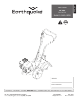
CRT 5050-5050GS User manual

Category
Mini tillers
Type
User manual
Shown with
Optional Bumper Guard
Rototiller
Operator's Manual
Includes Models
5050-5050GS
5055-5055GS
Pad #: 0M5050CRT
Rev. 1/01
0 Copyright 2001 Ardisam, Inc.
All Rights Reserved. Printed in USA.
TABLE OF CONTENTS
_ABLE OF CONTENTS
WARRANTY AND REGISTRATION
OPERATION SAFETY
Owner's Responsibility
Cautions and Important Notes
Important Safety Instructions
SAFETY SIGNS & DECALS
Safety Decals
UNPACKING AND ASSEMBLY
Unpack Tiller
Attach Handlebar to Tiller
Install the Drag Bar and Depth Regulator Lever
Fill Engine Crankcase
FEATURES
All CRT Models
CONTROLS
Drive Safety Control Levers
Reverse Handle
ADJUSTMENTS
Wheel Lockpins
Handlebar Height Adjustment
Depth Regulator Lever
Belt Tension Adjustment
1
2
3
3
3
3
5
5
7
7
7
8
8
9
9
10
10
10
11
11
11
12
12
OPERATION
Pre-Start Inspection
Starting and Stopping the Engine
Tilling
TIPS
Tilling Tips
Cultivating Tips
MAINTENANCE AND STORAGE
Check Forward Belt Tension
Change Forward/Reverse Belt
Check or Fill Engine Crankcase
Check Tiller Transmission Grease
Engine Maintenance
Clean Tine Axle Shaft
Check Tire Pressure
Prepare for Storage
Tiller and Engine Maintenance Schedule
TROUBLESHOOTING AND REPAIR
Troubleshooting Guide
Parts Listings
13
13
14
14
15
15
15
16
16
17
18
19
20
20
20
21
21
22
22
24
1
TWO YEAR
LIMITED WARRANTY
The Ardisam, Inc., Manufacturing Company warrants this
rototiller to be free from defects in material or workmanship.
Conditions of this warranty include:
What is covered under warranty:
For the first year from the date of purchase, Ardisam will
furnish 100% parts and labor to correct any defect caused
by faulty material or workmanship. During the second year
of ownership, Ardisam will furnish 100% of the parts to
correct any defect caused by faulty material or
workmanship. All repairs made under warranty must have
prior approval from Ardisam, Inc. Items subject to normal
wear and tear, such as belts, batteries, tines, shear bolts
and tires, due to the nature of their function are not
covered under this warranty. Any unit used in a
commercial application is covered for a period of 90
days after purchase. The engine is covered under a
separate warranty issued by the engine manufacturer
as stated in the engine manual.
What is not covered under warranty
.
This warranty applies only to products which have not been
repaired or altered outside our factory. It covers only
defects resulting from normal use, and does not cover
defects arising from misuse, alteration, negligence, or
accident. This warranty applies only to the original
purchaser, and is not transferrable.
This warranty supersedes all other warranties either
expressed or implied and all other obligations or
liabilities on our part Ardisam, Inc., does not assume,
and does not authorize any other person to assume for
us, any liability in connection with the sale of our
products. This guarantee is void unless the warranty
card is properly filled out and returned to Ardisam, Inc.,
Cumberland, Wisconsin, within two weeks of the
purchase date.
ARDISAM, INC.
ROWER GYRED,* 1ST SHELTERS * EDIOGIIERS
TREE STANDS * EMMEN SIMMERS * EDGERS
1360 1st Avenue; P.O. Sox 666
Cumberland, Wisconsin 54829
(715)822-2415 Fax
(715)822-4180
1-800-3456-007
sine attliaam.tom
WARRANTY AND REGISTRATION
Thank You . . .
for purchasing an Ardisam, Inc. CRT rototiller. We guarantee that this rototiller conforms to applicable North
American safety standards, and have worked to ensure that it will meet your exacting standards for usability
and durability. With proper care, your rototiller will provide many years of service.
Please take time to read this manual carefully to learn how to operate and service your rototiller
correctly Failure to do so could result in personal injury or equipment damage. This manual should be
considered a permanent part of your rototiller. Congratulations on your investment in quality
A
CAUTION
You must read, understand and comply with all safety
and operating instructions in this manual before
attempting to setup and operate this equipment.
Failure to comply with all safety and operating
instructions can result in loss of machine control,
serious personal injury to you and/or bystanders, and
risk of equipment and property damage. The triangle
in the text signifies important cautions or warnings
which must be followed.
A
CAUTION
Engine exhaust from this product contains chemicals
known, in certain quantities, to cause cancer, birth
defects, or other reproductive harm.
For easy reference, please record the
information on the chart below.
The Rototiller Reference Data can be found on the
identification tag located on the unit's left engine mount.
(Refer to the engine manual for location of engine
information and serial number.)
ROTOTILLER REFERENCE DATA
Model Description/Number
M/N (Manufacturers Number)
S/N (Serial Number)
Dealer Name
Date Purchased
4ENGINE
REFERENCE 0AT
Engine Make/Model
Engine ID/Serial Number
2
OPERATION SAFETY
,3ECTION CHECKLIST
Owner's Responsibility
Cautions and Important Notes
Important Safety Instructions
OWNERS RESPONSIBILITY
IMPORTANT SAFETY INSTRUCTIONS
Please read this section carefully.
Operate the tiller
according to the safety instructions and
recommendations outlined here and inserted throughout
the text. Make sure anyone who uses the tiller has read
the instructions and is familiar with the controls.
GENERAL
Safe and effective use of the rototiller is the owner's
responsibility.
Read and follow all safety instructions.
Maintain the tiller according to directions and schedule
included.
Ensure that anyone who uses the tiller is familiar with
all controls and safety precautions.
CAUTIONS AND IMPORTANT NOTES
Two symbols which draw attention to information of
special importance appear throughout this manual.
These comments range in importance from helpful hints
to warnings about risk of personal injury. Please take the
tie to read and understand them.
Indicates a situation which may cause personal
injury. It means - attention! Become alert! Your
safety is involved.
Provides helpfu information for proper assembly,
operation, or maintenance of your rototiller.
CAREFULLY READ THIS MANUAL AND FOLLOW
ALL INSTRUCTIONS.
Be familiar with all controls before operating the tiller.
Your tiller is equipped with a safety device that enables
you to stop the wheels and tines quickly in an
emergency. Learn how the drive control levers work
and how to control the tiller at all times.
Never allow children to operate the tiller. Keep small
children away from the area being tilled. Do not allow
adults to operate the tiller without proper instruction.
PREPARATION
Dress appropriately when operating the tiller. Always
wear sturdy footwear. Never wear sandals, sneakers,
or open shoes, and never operate the tiller with bare
feet. Do not wear loose clothing that might get caught
in moving parts.
Carefully inspect the area to be tilled, and remove all
foreign objects. Do not till above underground water
lines, gas lines, electric cables, or pipes. Do not
operate the tiller in soil with large rocks and foreign
objects which can damage the equipment.
Disengage all clutches and shift into neutral before
starting the engine.
Handle fuel with care; it is highly flammable.
Use an approved fuel container.
Never add fuel to a running engine or hot engine.
Fill fuel tank outdoors with extreme care. Never fill
fuel tank indoors.
Replace gasoline cap securely and clean up spilled
fuel before restarting.
Never attempt to make any adjustments while the
engine is running.
3
OPERATION SAFETY
OPERATION
Never operate the tiller without guards, covers, and
hoods in place.
Never start the engine or operate the tiller with the
wheels in the free-wheel position. Make sure the
wheel lockpins are engaged through wheel hubs and
wheel axle. Disengage wheel lockpins to permit free-
wheeling only when engine is stopped.
Keep hands, feet, and clothing away from rotating
parts. Keep clear of tiller tines at all times.
Tines and wheels rotate when tiller is engaged in
forward
or
reverse--
in
forward,
tines and wheels
rotate when the drive control levers are pulled down;
in
reverse,
wheels and tines rotate when the reverse
handle is pulled back towards the operator. Releasing
the drive control levers to
neutral
stops the wheels
and tines.
Be extremely cautious when operating in
reverse.
Take extra care to avoid slipping or falling, and to keep
feet clear of tines.
Exercise extreme caution when operating on or
crossing gravel drives, walks, or roads. Stay alert for
hidden hazards or traffic.
After striking a foreign object, stop the engine, remove
the wire from the spark plug, thoroughly inspect the
tiller for any damage, and repair the damage before
restarting and operating the tiller.
If vegetation clogs the tines, raise the handlebars to
elevate the tines, and run the tiller in
reverse.
If this
does not clean clogged vegetation from the tines,
STOP THE ENGINE AND DISCONNECT THE
SPARK PLUG WIRE
before removing vegetation by
hand.
Engine muffler will be hot from operation. Do not
touch it with bare skin or a severe burn may result.
If the unit should start to vibrate abnormally, stop the
engine and check immediately for the cause. Vibration
is generally a warning of trouble.
Do not run the engine indoors; exhaust fumes are
dangerous.
Do not overload the machine capacity by attempting
to till too
deep at too fast a rate.
Never operate the machine at high transport speeds
on slippery surfaces. Look behind and use care when
backing.
Never allow bystanders near the unit.
Use only attachments and accessories approved by
the manufacturer of the tiller.
Never operate the tiller without good visibility or light.
Be careful when tilling in hard ground. The tines may
catch in the ground and propel the tiller backward. If
this occurs, let go of the handlebars.
Take all possible precautions when leaving the
machine unattended. Disengage all controls levers,
stop the engine, wait for all moving parts to stop, and
make certain guards and shields are in place.
When leaving the operating position for any reason:
- shut off the engine.
- wait for all moving parts to stop.
MAINTENANCE AND STORAGE
Keep machine, attachments, and accessories in safe
working condition.
Check shear bolts, engine mounting bolts, and other
bolts at frequent intervals for proper tightness to be
sure the equipment is in safe working condition.
To prevent accidental starting, always disconnect the
spark plug wire from the spark plug before performing
tiller maintenance.
Never run the engine indoors. Exhaust fumes are
deadly.
Always allow muffler to cool before filling fuel tank.
Never store equipment with gasoline in the tank inside
a closed building where filmes may reach an open
flame or spark. Allow the engine to cool before storing
in any building.
Always refer to the operator's guide instructions for
important details if the tiller is to be stored for an
extended period.
4
LOCK-IN WHEELS
Never start or operate tiller with wheels in the
Free-Wheel position. Make sure wheel lockouts
are engaged through wheel hubs and axle.
To operate, tiller wheels must be kicked in.
Disengage wheel lockouts ONLY when engine
is stopped.
OPERATION
REFER TO OPERATORS MANUAL
FOR DETAILED OPERATING INSTRUCTIONS
TO START:
Release drive control levers to neutral position.
Lower the drag bar so that tines do not touch
the ground.
Check position of wheels and wheel lockouts.
Slide choke mond to choke position.
Move throttle control lever to fast position.
Pull starter rope.
LEILCRTA
AVOID SERIOUS INJURY OR DEATH
Read operators manual(s).
Know the location and function of all controls.
Keep all shields and guards in place and
working while running.
Never operate tiller when children are around.
Dress appropriately -- wear sturdy footwear.
Carefully inspect area to be tilled — remove
large rocks and other foreign objects.
Do NOT till above underground electric, water,
gas, or other utility fires and pipes.
STOP THE ENGINE AND DISCONNECT THE
SPARK PLUG WIRE before removing debris
or servicing unit.
When leaving the operating position
for any reason:
— shut off the engine.
— wait for all moving parts to stop.
A
DANGER
AVOID INJURY FROM
ROTATING TINES!
Keep hands, feet,
and clothing away.
Tines rotate when filler is
engaged in forward or reverse.
Tines and wheels rotate when
drive control levers are pulled
down.
In reverse, tines and wheels
rotate when the reverse handle is
pulled back toward the operator.
Releasing the drive control
levers to neutral steps the
wheels and tines.
Le.,5,6c
Part No. LBL821B
WARNING / Hood Decal
Part No. LBLCRTA
OPERATING INSTRUCTIONS /
Hood Decal
SAFETY SIGNS & DECALS
SAFETY DECALS
Safety warning decals are placed at strategic locations on the equipment as a constant reminder to the operator
of the most important precautions. All warning, caution and instructional messages on your equipment should be
carefully read and obeyed.
If any of these decals are lost or damaged. replace them at once.
They can be
purchased from Ardisam, Inc.
Part No. LBL516E
TINES DANGER / Hood Flap Decal
DO NOT START ENGINE UNLESS BELT
COVER IS ATTACHED. KEEP HANDS. FEET.
AND CLOTHING AWAY FROM MOVING BELTS
AND PULLEYS. FAILURE TO COMPLY COULD
RESULT IN INJURY SEE OWNER'S MANUAL
FOR FULL SAFETY INSTRUCTIONS.
Part No. LBL516C
WARNING / Belt Cover Decal
Part No. LBL516F
FREE HAND / Bumper Guard Decal
5
Earthquake
GEAR DRIVE
mowcy,..c
ROTOTILLER V
Part No. LBL304EQ
DECAL-Handlebar Dash (Earthquake)
:GARDEN STAR
GEAR DRIVE
ROTOTILLER
Part No. LBL304GS
DECAL-Handlebar Dash (Garden Star)
PAM COMM. Lain
TO IMAGE WHEELS WO TINFL
Part No. LBL516B
DECAL-Console (Forward Instructions)
LOCKER WHEELS
0
moor
Part No. LBLCRTA
DECAL-Tine Hood (Operating Instructions)
Part No. LBLCRTC
DECAL-Model CRT
A
DANGER
Mee WWII MOM
ROTAMO
11.,1••••• Owl
Nowimil•••••••••
4.4
5050/5055 Decals
Part No. LBL516C
DECAL-Belt Cover (Warning)
Part No. LBL516E
DECAL-Tine Hood Flap (Tine Danger)
PLACE R
H
AND H R
Part No. LBL516F
DECAL-Bumper Guard (Free Hand Warning), Optional
Part No. LBL821B
DECAL-Tine Hood (Warning)
6
lock nuts
height
adjustment
bolts
height
adjustment
holes
transmission
cover
height
adjustment
bolts
UNPACKING AND ASSEMBLY
SECTION CHECKLIST
Unpack Tiller
Attach Handlebar to Tiller
Install the Drag Bar
Fill Engine Crankcase
Your rototiller comes fully assembled except for a few
parts. The following instructions will help you unpack your
tiller and assemble and adjust your tiller's drag bar, cable
tension and handlebar height. You will need a 3/8",
2- 1/2", and 2-9116" wrenches and a pliers.
The right and left sides of your
rototiller are determined from the
operating position as you face the
direction of forward travel.
JNPACK TILLER
1. Open top of carton and remove handlebar assembly.
A
CAUTION
Do not try to lift the rototiller from the carton.
Find parts packet. Parts packet contains:
5- 3/8"-16 x 1" hex head bolts
5- 3/8%16 locknuts
1- 5/16%18 x 3/4" hex head bolt
1- 5/16"-18 locknut
1- detent pin
Cut open end of carton and remove machine by:
Removing lockpins on wheels.
Roll tiller from carton.
ATTACH HANDLEBAR TO TILLER
Place handlebar stems on outside of transmission
cover and align lower holes.
Insert one 3/8"-16 x 1" bolt for each side in lower
holes.
Start 3/8"-16 nuts on each bolt.
Insert one 3/8"-16 x 1" bolt for each side in upper
holes at desired handlebar height.
Tighten all 3/8"-16 nuts.
7
ENGINE IS SHIPPED FROM FACTORY
WITHOUT OIL. YOU MUST ADD ENGINE OIL
BEFORE STARTING ENGINE.
drag bar
bottom hole of
depth regulator
lever
drag bar linkage
depth regulator
lever
detent pin hole
DRAG BAR PROPERLY INSTALLED
Place engine level.
Remove oil filler
Fill to over flowing
Clean around oil fill
plug or dipstick,
for oil filler plug.
Add oil slowly -
Tighten plug/ dipstick
recheck.
firmly before starting.
OIL FILL PLUG
A
CAUTION
Do not add engine oil into gear case dipstick hole.
dipstick
gear case
dipstick hole
transmission
cover plate
NO ENGINE OIL!
INSTALL THE DRAG BAR
Install the depth regulator lever into the top of the
depth regulator bracket with handle facing rearward.
Insert detent pin through depth regulator bracket and
top hole of depth regulator lever--tines should clear the
ground.
NOTE: The rototiller is now in the tranaport position.
Insert one 3/8-16 x 1" bolt through rear of drag bar
and lower hole of depth regulator lever. Place nut on
end of bolt.
Align front hole in drag bar with hole in drag bar
linkage and insert one 5/16-18 x 3/4" bolt.
Place nut on bolt and tighten. Back off nuts so drag
bar can move freely when depth regulator lever is
raised or lowered.
UNPACKING AND ASSEMBLY
FILL ENGINE CRANKCASE
Add oil according to chart below. Do not overfill.
Use a high quality detergent oil classified "For Service
SC, SD, SE, SF, SG," such as Briggs & Stratton
"Warranty Certified" SAE 30 oil. Use no special
additives with recommended oils. Do not mix oil with
gasoline.
Always check oil level before starting engine. Refer to
engine manual for capacity.
Adapted from Briggs & Stratton Corporation, form No.272643-7/95.
9
FEATURES
ALL CRT MODELS
drive safety control lever
drag bar
forward cable
detent pin
bumper guard
optional
bumper guard
wheel lockpin
reverse handle
reverse cable
belt guard
recoil start
serial number plate
reverse handle
As a safety precaution, the drive control levers will
not lock in the forward position.
Cr To stop the wheels and tines at any time, release
the drive control levers.
IMPOIMTANT
As a safety precaution, the reverse handle will not
lock in reverse.
4. To stop the wheels and tines at any time, release
the reverse handle.
+ Do not operate both the reverse handle and drive
control levers at the same time.
SECTION CHECKLIST
Drive Safety Control Levers
Reverse Handle
A
CAUTION
This information is provided here only to introduce the
controls. DO NOT START THE ENGINE AT THIS TIME.
Starting and operating instructions are given on page
16. Please read this section and all operating and safety
instructions before starting your tiller.
A
CAUTION
ENGINE SHOULD BE OFF BEFORE ADJUSTING
ANY CONTROLS!
CONTROLS
REVERSE HANDLE
Engages wheels and tines in reverse.
Pulling reverse handle back towards operator reverses
tiller.
DRIVE CONTROL LEVERS
Engage wheels and tines into forward, releasing returns
machine to neutral.
Pulling down on drive control levers engages the wheels
and tines. Releasing drive control levers disengages the
wheels and brings the tiller to a complete stop.
A
CAUTION
Extreme caution should be used when operating
rototiller in the reverse direction.
10
Wheel lockpin in free-wheel position.
(axle hole only)
high
medium
low
3/8"-16 x 1"
bolt
3
HANDLEBAR HEIGHT SETTINGS
ADJUSTMENTS
SECTION CHECKLIST
Wheel Lockpins
Handlebar Height Adjustment
Drag Bar
Belt Tension Adjustment
A
CAUTION
ENGINE SHOULD BE OFF BEFORE LOCKING OR
UNLOCKING WHEELS.
WHEEL LOCKPINS
Place wheels in tilling position.
1. Remove lockpin. Align hole in axle with hole in wheel
hub.
A
CAUTION
Never start engine or operate tiller with wheels in free-
wheel position. The free-wheel position is for
transporting the tiller long distances over level ground-
-do not attempt to move the tiller up or down steep
grades in the free-wheel position.
HANDLEBAR HEIGHT ADJUSTMENT
Adjust handlebar height.
The ideal height of the handlebar varies with operator
height and the depth of tilling. To adjust handlebar height:
Unscrew nuts and remove top bolt until handlebar
moves freely up and down.
Align handlebar to desired hole on the transmission
cover.
Insert lockpin through holes, fold lockpin ring to secure
pin to axle.
Wheel and axle should be firmly locked together
before tilling.
Repeat for other wheel.
3. Install bolts and nuts. Retighten.
NOTE: Always have both wheel lockpins in or out. Do
not operate tiller with only one wheel locked.
To place wheels in free-wheel position.
Remove lockpin. Slide wheel inward toward machine.
Insert pin in axle only.
Wheel should turn freely on axle.
11
upper jam nut
lower jam nut
forward cable ,
0.
reverse cable
bracket
ADJUSTMENTS
v
r
DEPTH REGULATOR LEVER
Tilling depth is controlled by the height of the depth
regulator lever.
To adjust tilling depth.
Remove detent pin.
Raise the depth regulator lever to position tines at
chosen tilling depth.
Align hole in depth regulator lever with hole in depth
regulator bracket and replace detent pin.
Depth Regulator Lever Down =
Shallower tilling. Place
the detent pin in the top hole of the depth regulator lever
for shallowest tilling.
Depth Regulator Lever Up =
Deeper tilling. Place the
detent pin in the bottom hole of the depth regulator lever
for deepest tilling.
A
CAUTION
Always set the depth regulator lever in the transport
position before starting engine, that is, place the detent
pin in the highest hole of the depth regulator lever.
A
CAUTION
Do not adjust tilling depth unless drive control levers
are released to neutral position.
BELT TENSION ADJUSTMENT
Proper belt tension is critical to good performance. After
1/2 hour of operation, all cables may have to be adjusted
due to initial stretch. Thereafter, check tension after every
2 hours of operation.
To increase belt tension:
1. Loosen upper jam nut. Turn nut up cable in 1/8"
increments.
Tighten lower jam nut.
Check adjustment.
This procedure can be repeated until conduit adjustment
bolts have no more adjustment left. If no more
adjustment can be made, belt may have to be replaced.
12
ENGINE IS SHIPPED FROM FACTORY WITHOUT
OIL.YOU MUST ADD ENGINE OIL BEFORE
STARTING ENGINE.
OPERATION
SECTION CHECKLIST
Pre-Start Inspection
Starting and Stopping the Engine
Tilling
PRE-START INSPECTION
Make sure all safety guards are in place and all nuts
and bolts are secure.
Check oil level in engine crankcase. See your engine
manual for procedure and specifications.
Inspect air cleaner for cleanliness. See your engine
manual for procedure.
Check the fuel supply. Fill the fuel tank no closer than
1/4 to 1/2 inch of top of tank to provide space for
expansion. See your engine manual for fuel
recommendations.
Be sure spark plug wire is attached and spark plug is
tightened securely.
Check position of wheels and wheel lockouts.
Check drag bar position.
AS
CAUTION
Please do not start your tiller until you have read the
Manual that came with your engine, and the sections
in this manual titled Controls, Adjustments and Safety.
If you have read these, follow the steps below to start
your tiller. Always perform this pre-start checklist before
starting the engine.
AS
CAUTION
Gasoline is highly flammable and must be handled with
care. Never fill the tank when the engine is hot or
running. Always move outdoors to fill the tank.
A
CAUTION
Wheels must always be locked in the TILLING position
when engine is running. Do not operate the tiller with
the wheel lockouts unlocked. Always set the wheels in
tilling position before starting engine.
A
CAUTION
Always put the drag bar in the transport position before
starting engine. Tines should clear the ground.
13
CLVIPORTANT)
ENGINE IS SHIPPED FROM FACTORY WITHOUT
OIL.YOU MUST ADD ENGINE OIL BEFORE
STARTING ENGINE
To stop the engine at any time, move throttle control
to the off position. To stop wheels and tines at any
time, release drive control levers to neutral position.
CIMPORTAN_ID
Practice operating the controls and tiller with tines out
of ground before beginning to till. It is important that
you know how to use the tiller properly, how to keep
control at all times, how to stop the tines and wheels
from turning, and how to stop the engine if necessary.
If you do not know how to do these things, read the
Controls, Adjustments and Safety sections before
proceeding.
OPERATION
STARTING AND STOPPING THE
ENGINE
NOTE: Refer to engine manual for proper operating
instructions.
A
CAUTION
Always keep hands and feet clear of rotating machine
parts.
A
CAUTION
Temperature of muffler and near by areas may exceed
150° F. Avoid these areas.
A
CAUTION
Do not move choke control to CHOKE to stop engine.
Backfire or engine damage may occur.
TILLING
Adjust the drag bar to desired tilling depth.
NOTE: Raise drag bar up
one
hole at a time, testing
tiller operation after each raise. Raising drag bar too
high can result in loss of control of tiller!
Move the throttle control to
fast
Place the tiller in
forward
by pushing down on the
drive control levers--this will engage the wheels and
tines.
NOTE: You can slow the tiller's forward advance at
any time by putting slight downward pressure on the
handlebars, or you can stop the tiller by releasing the
drive control levers to the neutral position.
A
CAUTION
To stop wheels and tines at any time, release drive
control levers to neutral position.
A
CAUTION
Always release drive control levers to neutral position
before adjusting the drag stake.
14
TIPS
TILLING TIPS
The key to successful tilling is to begin with a shallow
cut on the first pass, and then work an inch or two
deeper on each successive pass.
Tilling depth will vary with ground conditions.
When beginning to till in unbroken ground or in
extremely hard soil, set the detent pin in the highest
hole of the drag bar (follow instructions under Tilling
on previous page). This will allow for shallow tilling.
With the drag bar in this position, make several
light passes over the area to be tilled. Reset for
deeper depths with successive passes.
If tiller jumps or skids uncontrollably, lower the drag
bar by placing the detent pin in a higher hole. This
will allow for shallower tilling. Hold firmly to the
handlebars to control sudden lurches.
If weeds, tall grasses, vines, or other materials clog
or jam the tines, reverse tine direction to unwind
vegetation.
Immediately release the drive control levers if the tines
jam or you strike a foreign object With drive control
fevers in neutral, push throttle control to
stop
position
to stop the engine. Disengage the spark plug wire.
When tines have stopped, remove foreign objects and
check for damage.
CULTIVATING TIPS
If you plan to use your tiller for cultivating:
Plant rows on 20° - 22" centers for ease of turning.
Set the drag bar with the detent pin in one of the
higher holes. This will allow the shallow cultivation
necessary to turn over weeds, and break up and
aerate the soil.
A
CAUTION
Extreme caution must be taken in selecting tilling depth.
If you attempt to till too deeply for soil conditions, that
is, with the drag bar in too high a position, loss of control
could result.
A
CAUTION
If removing material from the tines by hand, stop engine
and remove spark plug wire first.
15
.• A CAUTION
To prevent accidental starting:
wire
Engine must be turned off and cool, and spark plug
wire must be removed from spark plug before checking
and adjusting engine or equipment.
SECTION CHECKLIST
Check Forward Belt Tension
Change Forwaed/Reverse Belt
Check or Fill Engine Crankcase
Check Tiller Transmission Grease
Engine Maintenance
Clean Tine Axle Shaft
Check Tire Pressure
Prepare for Storage
Tiller and Engine Maintenance Schedule
CHECK FORWARD BELT TENSION
Forward belt tension may decrease over time. It must be
adjusted within the first half hour of operation, and
checked after every two hours of operation. Proper
adjustment will assure long belt life. Too much or too little
belt tension will cause premature belt failure. To check
and adjust the forward belt tension:
Turn off engine. Engine must be cool.
Remove spark plug wire from spark plug.
With drive control levers in neutral position, measure
length of spring when compressed.
Pull down on drive control levers and measure length
of spring when stretched out. Ideal length would be
1/4" longer.
MAINTENANCE AND STORAGE
A CAUTION
Check forward belt tension regularly. Too much or too
little tension will cause premature belt failure.
16
MAINTENANCE AND STORAGE
CHANGE FORWARD/REVERSE BELT
Turn off engine. Engine must be cool.
Remove spark plug wire from spark plug.
Remove belt guard.
remove the forward belt from the forward engine
pulley:
- gently pull the engine recoil rope to rotate the
pulley.
- with the pulley turning, force the forward belt out
of the V-groove.
- slide the belt free of the engine pulley.
- pull the forward belt down and out of the way.
remove the reverse belt from the reverse engine
pulley:
gently pull the engine recoil rope to rotate the
pulley.
with the pulley turning, force the reverse belt out
of the V-groove.
- slide the belt free of engine pulleys and reverse
belt guides.
- pull belt down and away from transmission
pulley.
install new reverse belt:
- thread belt up from bottom.
- place belt around transmission pulley in groove.
- place belt under reverse belt guides.
gently pull engine recoil rope while forcing the
belt over the edge of the engine pulley into the
V-groove.
install new forward belt:
- place forward belt in transmission pulley groove.
- gently pull the engine recoil rope to rotate the
pulley while forcing the forward belt into the
V-groove.
Replace belt guard.
Attach spark plug wire.
BELT REPLACEMENT PART #'S:
727A (forward)
726 (reverse) 2000 models
730 (reverse) 2001 models
17
OIL FILL PLUG
Place engine level.
Remove oil filler
Fill to over flowing
Clean around oil fill,
plug or dipstick.
for oil filler plug.
Add oil slowly -
Tighten plug/ dipstick
recheck,
firmly before starting
ENGINE IS SHIPPED FROM FACTORY WITHOUT
OIL.YOU MUST ADD ENGINE OIL BEFORE
STARTING ENGINE.
CHECK OR FILL ENGINE
CRANKCASE
Add and change oil according to chart below.
Do not
overfill.
Use a high quality detergent oil classified For
Service SC, SD, SE, SF, SG," such as Briggs &
Stratton "Warranty Certified" SAE 30 oil. Use no
special additives with recommended oils. Do not mix
oil with gasoline.
2. Always check oil level before starting engine. Add oil
as shown below. Refer to engine manual for capacity.
Adapted from Briggs & Stratton Corporation, form No. 272643-7/95.
MAINTENANCE AND STORAGE
SAE Viscosity Grades
30
i
P5W-33. ,1,M
0W-33U
0
,
Synthetic 5W-05W-0
M
_
°F
-20
0
20
32
0
60
80
100
Adapted from Briggs & Stratton Corporation, form No. 272646-10/93.
*Air cooled engines run hotter than automotive engines. Use of
multi-viscosity oils (10W-30, etc.) above 40
°
F (4
°
C) will result in
high oil consumption and possible engine damage. Check oil
level more frequently if using these types of oils.
**SAE 30 oil, if used below 40
°
F (4
°
C), will result in hard
starting and possible engine bore damage due to inadequate
lubrication.
fb
18
  • Page 1 1
  • Page 2 2
  • Page 3 3
  • Page 4 4
  • Page 5 5
  • Page 6 6
  • Page 7 7
  • Page 8 8
  • Page 9 9
  • Page 10 10
  • Page 11 11
  • Page 12 12
  • Page 13 13
  • Page 14 14
  • Page 15 15
  • Page 16 16
  • Page 17 17
  • Page 18 18
  • Page 19 19
  • Page 20 20
  • Page 21 21
  • Page 22 22
  • Page 23 23
  • Page 24 24
  • Page 25 25
  • Page 26 26
  • Page 27 27
  • Page 28 28
  • Page 29 29
  • Page 30 30
  • Page 31 31
  • Page 32 32
  • Page 33 33
  • Page 34 34
  • Page 35 35
  • Page 36 36
  • Page 37 37
  • Page 38 38
  • Page 39 39
  • Page 40 40

CRT 5050-5050GS User manual

Category
Mini tillers
Type
User manual

Ask a question and I''ll find the answer in the document

Finding information in a document is now easier with AI