Page is loading ...

M16 x 2 41
M20 x 2.5 81
M22 x 2.5 109
M24 x 3 139
M30 x 3.5 281
⅝30
¾50
⅞80
1123
1⅛ 195
KEYSTONE FIGURE 129/239/139
INSTALLATION, OPERATION AND MAINTENANCE MANUAL
Before installation, these instructions must be fully read and understood
1. Torques based on 100 Mpa induced stress
infastener threads.
2. Values are based on steel bolting well
lubricated with a heavy graphite and
oilmixture.
3. For cadmium plated fasteners multiply
torque x0.75.
4. For zinc plated fasteners multiply torque
x1.40.
5. Recommended torques are a minimum.
Formaximum torque multiply torque x 1.05.
CAUTION - indicates that it may lead to
injuries or damages on the properties.
WARNING - indicates that it may lead
human body to serious injuries.
DANGER - indicates that it may lead
human body to death.
TECHNICAL DATA
Flange accommodation: Figure 129/239/139
are designed by
ASME Class150,
AS 2129 Table E
JIS 16K
Pressure rating: 14 bar (200 psi)
Temperature range: -40°C to 120°C
(-40°F to 248°F)
CARRIAGE AND STORAGE
1. Carriage
The valve shall be carried safely not to be
impacted or affected by other object.
Especially, the wheel of operator and disc edge
shall be protected by any means.
2. Storage
The valve shall be stored in the higher place
which is able to prevent from being submerged
in water and keep off from penetration of
rainwater or cover it with waterproof cloth,
which Keystone valve LLC. does not provide,
toavoid being wetted.
When worker installs the valve, remove
the dust and extraneous substances after
disassembling the pallet and protective cover.
INSTALLATION
The valves are shipped with flange surface
protection. Before installing the valve, remove
the protection.
CAUTION
The valve should be installed in the slight open
position whether the gap between disc edge and
body flange face is about 10 mm to insure that the
seat and disc are not damaged during installation.
Particular care should be taken with valves
equipped with "single acting" actuators.
Failure to insure proper handling may result
indamage to the valve.
If the pipe is lined, confirm that the disc rotation
does not contact the lining during the opening
stroke.
Failure to confirm that the disc rotation dose
not contact the lining may result in damage
tothevalve.
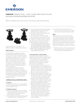
The Figure 129/239/139 valves are
bi-directional and will control flow equally well
in either direction.
© 2017 Emerson. All Rights Reserved.Emerson.com/FinalControl VCIOM-02832-EN 21/11
FIGURE 1
PIPE FLANGE BOLT TIGHTENING TORQUE
Bolt size
Recommended torque
Nm
Bolt size Recommended torque
U.N.C Ft·lbs

2
KEYSTONE FIGURE 129/239/139
INSTALLATION, OPERATION AND MAINTENANCE MANUAL
Installation in new construction using welding
type flanges
1. With the disc in the slight opened position,
align and center the companion flange bolt
holes to the body alignment holes (Figure
239/139) or lug holes (Figure 129).
2. Assemble the body and flanges with the
flange bolting and make-up the bolting.
3. Using the flange-body-flange assembly for
fit-up and centering to the pipe.
4. Tack weld the flanges to the pipe.
5. Remove the flange bolting and valve
assembly from between the flanges.
CAUTION
Do not finish weld the flanges to the pipe with the
valve bolted between the flanges as this will result
in serious heat damage to the valve seat.
6. Finish welding the flanges to the pipe and
allow the flanges to cool completely before
proceeding.
FIGURE 2
FIGURE 3
FIGURE 4
FIGURE 5
MAINTENANCE
Routine maintenance or lubrication is not
required.
Be sure to be familiar with following facts
before installing.
Tie up with rope when handling the butterfly
valve assembly for Figure 129/239/139.
1. Tie up feature with rope when handling
the valve assembly vertically. (Figure 2)
Liftthevalve in the condition of tying upper
neck with ropes. Tie up the front and rear
side of valve with two ropes, because the
rope may be removed when use one rope.
2. Tie up feature with rope when handling the
valve assembly horizontally. (Figure 3, 4) Lift
the valve in the condition of tying upper and
lower neck with ropes. Beware that the rope
on the lower neck may not be removed or
valve assembly may not be tilted.
Dismantling the valve from pipe (Figure 5)
1. Be sure that the fluid and pressure in
valve and pipe must be removed before
dismantling.
2. Close the valve.
3. Cut off the supply of the electric power,
hydraulic or pneumatic pressure depending
on the kinds of operators attached and
disconnect the electric cable, hydraulic or
pneumatic hoses.
4. Release the flange bolt in order to
disassemble the valve assembly.
Disassemble the operator ahead when
necessary.
5. Dismantle the valve after open the flanges
sufficiently using tools.
6. Disassembly the operator in the condition of
fastening the valve assembly on vise.
WARNING
Make sure that the fluid and hydraulic or
pneumatic pressures in valve, operator and pipe
are removed, and then dismantle the disc in the
position of full close after taking safety measures.
DANGER
Use the rope made by synthetic fiber only
taking into account of valve weight and safety
andpayattention that paint on the valve does not
peel. When worker lifts the valve assembly, which
is equipped hand wheel including gear box, in the
condition of tying hand wheel with rope, he(she)
shall comply with the specific method which
manufacturer provides because the stem may be
distorted or the cover may be damaged.

3
KEYSTONE FIGURE 129/239/139
INSTALLATION, OPERATION AND MAINTENANCE MANUAL
DISASSEMBLY
CAUTION
When assembling or disassembling the valve,
workers have to be careful that each component
including disc edge shall not be damaged.
Disassembly of the Figure 129 valve,
sizeNPS2to 20 (Figure 6)
1. Remove the disc screws and O-ring for
thevalves.
2. Open the disc.
3. Remove the stem by pulling it out through
the valve top plate.
4. Remove the disc from the valve body
bypulling or “rolling” the disc out of
theseatbore.
5. Remove the seat by hitting on side of the
seat with a rubber hammer.
6. Remove the bushing, packing and inspect
for damage. Replace if needed.
Disassembly of the Figure 239/139 valve,
sizeNPS 2 to 20 (Figure 7)
1. Remove the disc screws and O-ring for
thevalves.
2. Open the disc.
3. Remove the stem by pulling it out through
the valve top plate.
4. Remove the disc from the valve body
bypulling or “rolling” the disc out of the
seatbore.
5. Remove the seat by hitting on side of
theseat with a rubber hammer.
6. Remove the bushing, packing and inspect
for damage. Replace if needed.
FIGURE 6
FIGURE 7
Bushing
Packing
Stem
Body
Seat and O-ring
Disc
O-ring and disc screw
Bushing
Packing
Stem
Body
Seat and O-ring
Disc
O-ring and disc screw

4
10 mm
KEYSTONE FIGURE 129/239/139
INSTALLATION, OPERATION AND MAINTENANCE MANUAL
INSPECTION OF VALVE COMPONENTS
• Inspect the body for any corrosion and
damage.
• Inspect the seat for any wear and damage.
• Inspect around the disc edge for any scratch.
If there is any scratch on disc edge, polish the
edge with sandpaper.
• Use the electric powered wire brush in order
to polish the disc edge.
• Use the lathe machine to finish polishing or
sanding, when necessary.
FIGURE 8
FIGURE 9
FIGURE 10
ASSEMBLY
Assembly of Figure 129/239/139 valve,
sizeNPS2 to 20
1. Clean all components and settle the valve
body on the vise.
2. Insert the packing and bushing to the upper
side of the body. (Figure 8)
3. Locate the body in the horizontal position
and insert the seat to inside of the body by
hitting with a rubber hammer adjusting the
stem hole of seat to the stem hole of lower
body. (Figure 9)
4. Adjust the stem holes tin the body and seat
by thrusting in and pulling out using stem
or T-shape jig, and then thrust the stem into
the stem hole with protruding the screwed
part 10 mm. (Figure 10)
5. Apply silicon oil to the inner seat and adjust
the upper stem hole of disc to the protruded
screwed part of upper side. Then, push and
insert the disc until the lower side of disc set
to the lower stem hole. (Figure 11)
6. Drive the stem into the body until adjust
the holes between stem, disc and screw
holes be matched using rubber hammer.
And adjust the screw hole center of stem
byrotating the disc. (Figure 12)
7. Adjust the screw holes between stem and
disc correctly using pin or screwdriver and
fasten the screw tightly after inserting the
O-ring onto the disc screw. (Figure 13)
8. Finish assembling the valve. (Figure 14)
FIGURE 11
FIGURE 14
FIGURE 12
FIGURE 13

5
10 mm
KEYSTONE FIGURE 129/239/139
INSTALLATION, OPERATION AND MAINTENANCE MANUAL
Install the valve assembly into the pipe
1. Fix the valve on the vise and install the
worm gear box and actuator.
2. Check the condition whether the gap
between disc edge and body flange is about
10 mm. (Figure 15)
CAUTION
Workers shall pay attention to the position of disc
because disc edge may be damaged when the
disc is opened more than the face of body flange,
and the excessive torque may be caused by the
distortion of seat when fasten the flange bolt in
the state of entire closure.
3. Insert the valve after widening the flanges
sufficiently. The gap between flanges shall
be wider than the width of valve. When insert
the valve in the condition of insufficient
flange gap, the seat may be distorted or torn
and cause the leakage. (Figure 16)
4. Adjust the valve alignment hole or tap hole
to the flange hole, pass the bolt through the
flange hole, alignment hole or tap hole and
check the position of valve. Tighten the bolt
with hand if there is no problem. (Figure 17)
5. Open the disc fully by operating handle in
order to check whether or not the edge of
pipe and disc edge contact each other.
6. After making sure of smooth operating of
valve, fasten the bolts with the tool by the
diagonal sequence in the condition of full
opening.
7. Finish installing the valve assembly onto
thepipe (Figure 18)
CAUTION
Do not use the flange gaskets.
FIGURE 16
FIGURE 17
FIGURE 18
FIGURE 15

6
VCIOM-02832-EN © 2018, 2021 Emerson Electric Co. All rights reserved 11/21. Keystone is a mark owned by one of the companies in the Emerson Automation Solutions
business unit of Emerson Electric Co. The Emerson logo is a trademark and service mark of Emerson Electric Co. All other marks are the property of their prospective owners.
The contents of this publication are presented for informational purposes only, and while every effort has been made to ensure their accuracy, they are not to be construed
as warranties or guarantees, express or implied, regarding the products or services described herein or their use or applicability. All sales are governed by our terms and
conditions, which are available upon request. We reserve the right to modify or improve the designs or specifications of such products at any time without notice.
Emerson Electric Co. does not assume responsibility for the selection, use or maintenance of any product. Responsibility for proper selection, use and maintenance of
any Emerson Electric Co. product remains solely with the purchaser.
Emerson.com/FinalControl
TROUBLESHOOTING
Symptom Possible cause Resolution
Valve opens only a few degrees and stops
(Itwill not open to the full angle desired)
1. The valve is improperly aligned and improper
installation
1. Loosen the flange bolts, realign the valve with flanges and
retighten the flange bolts to correct torque per ANSI requirement
Leakage past the flange face 1. Flange bolts are not evenly torqued 1. Loosen the flange bolts and tighten the flange bolts to correct
torque per ANSI requirements
2. Improper flanges 2. Refer to flange accommodation on page 1
Leakage in the closed position
(Leakageinthe pipe line)
The disc is not closing fully:
1. Actuator is not properly adjust 1. Refer to the adjustment procedures
2. Damaged seat 2. Replace seat
3. Line pressure exceeds valve’s working pressure 3. Reduce line pressure to valve working pressure
4. Damaged valve disc 4. Replace disc
Leakage at the valve stem 1. Seat stem hole or packing failure 1. Refer to valve disassembly procedures
Water hammer 1. The valve is closing too quickly 1. Adjust the actuator
Excessively high torque 1. Obstruction in the pipe line 1. Remove the valve from pipe line and remove obstruction
2. Valve stem or disc bent 2. Return the valve to factory for disc or stem replacement
(Checkfor water hammer or freezing of line material)
3. Scale build-up on stem or seat 3. Open and close the valve several times, operate the valve at least
once a month, check the valve seat for deterioration
KEYSTONE FIGURE 129/239/139
INSTALLATION, OPERATION AND MAINTENANCE MANUAL
/