
POWER AVAILABILITY
Nfinity
™ Power System
USER MANUAL
105/210V
50/60Hz
4 to 16 kVA


i
TABLE OF CONTENTS
IMPORTANT SAFETY INSTRUCTIONS . . . . . . . . . . . . . . . . . . . . . . . . . . . . . . . . . . . . . . . . . . . . . . . .1
GLOSSARY OF SYMBOLS . . . . . . . . . . . . . . . . . . . . . . . . . . . . . . . . . . . . . . . . . . . . . . . . . . . . . . . .2
1.0 I
NTRODUCTION
1.1 General Description . . . . . . . . . . . . . . . . . . . . . . . . . . . . . . . . . . . . . . . . . . . . . . . . . . . . . . . . . . 3
1.1.1 System Description. . . . . . . . . . . . . . . . . . . . . . . . . . . . . . . . . . . . . . . . . . . . . . . . . . . . . . . . . . . . 3
1.2 Modes of Operation. . . . . . . . . . . . . . . . . . . . . . . . . . . . . . . . . . . . . . . . . . . . . . . . . . . . . . . . . . . 5
1.3 Major Components . . . . . . . . . . . . . . . . . . . . . . . . . . . . . . . . . . . . . . . . . . . . . . . . . . . . . . . . . . . 6
1.3.1 Unit Frame . . . . . . . . . . . . . . . . . . . . . . . . . . . . . . . . . . . . . . . . . . . . . . . . . . . . . . . . . . . . . . . . . . 6
1.3.2 User Interface Module . . . . . . . . . . . . . . . . . . . . . . . . . . . . . . . . . . . . . . . . . . . . . . . . . . . . . . . . . 6
1.3.3 System Control Module . . . . . . . . . . . . . . . . . . . . . . . . . . . . . . . . . . . . . . . . . . . . . . . . . . . . . . . . 6
1.3.4 Power Module . . . . . . . . . . . . . . . . . . . . . . . . . . . . . . . . . . . . . . . . . . . . . . . . . . . . . . . . . . . . . . . . 7
1.3.5 Battery Module . . . . . . . . . . . . . . . . . . . . . . . . . . . . . . . . . . . . . . . . . . . . . . . . . . . . . . . . . . . . . . . 7
2.0 INSTALLATION
2.1 Inspection . . . . . . . . . . . . . . . . . . . . . . . . . . . . . . . . . . . . . . . . . . . . . . . . . . . . . . . . . . . . . . . . . . 8
2.1.1 Environment . . . . . . . . . . . . . . . . . . . . . . . . . . . . . . . . . . . . . . . . . . . . . . . . . . . . . . . . . . . . . . . . . 8
2.1.2 Required Setup Equipment . . . . . . . . . . . . . . . . . . . . . . . . . . . . . . . . . . . . . . . . . . . . . . . . . . . . . 8
2.1.3 Site Preparation . . . . . . . . . . . . . . . . . . . . . . . . . . . . . . . . . . . . . . . . . . . . . . . . . . . . . . . . . . . . . . 8
2.2 Unloading . . . . . . . . . . . . . . . . . . . . . . . . . . . . . . . . . . . . . . . . . . . . . . . . . . . . . . . . . . . . . . . . . . 9
2.2.1 Unloading the UPS. . . . . . . . . . . . . . . . . . . . . . . . . . . . . . . . . . . . . . . . . . . . . . . . . . . . . . . . . . . . 9
2.2.2 Stationary Mounting . . . . . . . . . . . . . . . . . . . . . . . . . . . . . . . . . . . . . . . . . . . . . . . . . . . . . . . . . 10
2.3 Cable Installation . . . . . . . . . . . . . . . . . . . . . . . . . . . . . . . . . . . . . . . . . . . . . . . . . . . . . . . . . . . 11
2.3.1 Wiring Preparation. . . . . . . . . . . . . . . . . . . . . . . . . . . . . . . . . . . . . . . . . . . . . . . . . . . . . . . . . . . 11
2.3.2 Connecting to External Panel Boards . . . . . . . . . . . . . . . . . . . . . . . . . . . . . . . . . . . . . . . . . . . . 13
Input Cabling and Protection . . . . . . . . . . . . . . . . . . . . . . . . . . . . . . . . . . . . . . . . . . . . . . . . . . 13
Output Cabling . . . . . . . . . . . . . . . . . . . . . . . . . . . . . . . . . . . . . . . . . . . . . . . . . . . . . . . . . . . . . . 14
2.3.3 REPO Connection . . . . . . . . . . . . . . . . . . . . . . . . . . . . . . . . . . . . . . . . . . . . . . . . . . . . . . . . . . . . 15
2.4 Communications. . . . . . . . . . . . . . . . . . . . . . . . . . . . . . . . . . . . . . . . . . . . . . . . . . . . . . . . . . . . 16
2.4.1 COM Ports. . . . . . . . . . . . . . . . . . . . . . . . . . . . . . . . . . . . . . . . . . . . . . . . . . . . . . . . . . . . . . . . . . 16
2.4.2 Intellislot™ Ports . . . . . . . . . . . . . . . . . . . . . . . . . . . . . . . . . . . . . . . . . . . . . . . . . . . . . . . . . . . . 16
3.0 OPERATING INSTRUCTIONS
3.1 Controls and Indicators . . . . . . . . . . . . . . . . . . . . . . . . . . . . . . . . . . . . . . . . . . . . . . . . . . . . . . 17
3.1.1 Display Controls . . . . . . . . . . . . . . . . . . . . . . . . . . . . . . . . . . . . . . . . . . . . . . . . . . . . . . . . . . . . . 17
3.2 Status LED Modes . . . . . . . . . . . . . . . . . . . . . . . . . . . . . . . . . . . . . . . . . . . . . . . . . . . . . . . . . . 18
3.3 Navigating the Menu . . . . . . . . . . . . . . . . . . . . . . . . . . . . . . . . . . . . . . . . . . . . . . . . . . . . . . . . 18
3.4 Operating Procedures. . . . . . . . . . . . . . . . . . . . . . . . . . . . . . . . . . . . . . . . . . . . . . . . . . . . . . . . 19
3.4.1 Start-Up and Initialization . . . . . . . . . . . . . . . . . . . . . . . . . . . . . . . . . . . . . . . . . . . . . . . . . . . . 19
3.4.2 Shutting Down the UPS. . . . . . . . . . . . . . . . . . . . . . . . . . . . . . . . . . . . . . . . . . . . . . . . . . . . . . . 19
3.4.3 Manual Transfer to Bypass . . . . . . . . . . . . . . . . . . . . . . . . . . . . . . . . . . . . . . . . . . . . . . . . . . . . 19

ii
3.5 Main Menu . . . . . . . . . . . . . . . . . . . . . . . . . . . . . . . . . . . . . . . . . . . . . . . . . . . . . . . . . . . . . . . . 20
3.5.1 UPS Status Screen . . . . . . . . . . . . . . . . . . . . . . . . . . . . . . . . . . . . . . . . . . . . . . . . . . . . . . . . . . . 21
3.5.2 UPS Configuration Screen . . . . . . . . . . . . . . . . . . . . . . . . . . . . . . . . . . . . . . . . . . . . . . . . . . . . . 22
3.5.3 Display Date/Time . . . . . . . . . . . . . . . . . . . . . . . . . . . . . . . . . . . . . . . . . . . . . . . . . . . . . . . . . . . 27
3.5.4 Event Log . . . . . . . . . . . . . . . . . . . . . . . . . . . . . . . . . . . . . . . . . . . . . . . . . . . . . . . . . . . . . . . . . . 28
3.5.5 Active Alarms . . . . . . . . . . . . . . . . . . . . . . . . . . . . . . . . . . . . . . . . . . . . . . . . . . . . . . . . . . . . . . . 28
3.5.6 Transfer to Bypass . . . . . . . . . . . . . . . . . . . . . . . . . . . . . . . . . . . . . . . . . . . . . . . . . . . . . . . . . . . 28
3.5.7 Module Replacement . . . . . . . . . . . . . . . . . . . . . . . . . . . . . . . . . . . . . . . . . . . . . . . . . . . . . . . . . 29
3.5.8 Service Tools for Liebert Global Services Engineers . . . . . . . . . . . . . . . . . . . . . . . . . . . . . . . . 30
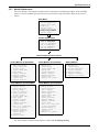
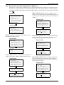
4.0 TROUBLESHOOTING
4.1 Active Alarms . . . . . . . . . . . . . . . . . . . . . . . . . . . . . . . . . . . . . . . . . . . . . . . . . . . . . . . . . . . . . . 31
4.2 Module LED Indication . . . . . . . . . . . . . . . . . . . . . . . . . . . . . . . . . . . . . . . . . . . . . . . . . . . . . . 33
4.3 Module Replacement . . . . . . . . . . . . . . . . . . . . . . . . . . . . . . . . . . . . . . . . . . . . . . . . . . . . . . . . 34
4.3.1 Removing Modules . . . . . . . . . . . . . . . . . . . . . . . . . . . . . . . . . . . . . . . . . . . . . . . . . . . . . . . . . . . 34
4.3.2 Adding or Replacing Modules . . . . . . . . . . . . . . . . . . . . . . . . . . . . . . . . . . . . . . . . . . . . . . . . . . 35
4.3.3 Replacing the User Interface . . . . . . . . . . . . . . . . . . . . . . . . . . . . . . . . . . . . . . . . . . . . . . . . . . . 35
5.0 MAINTENANCE
5.1 Maintenance . . . . . . . . . . . . . . . . . . . . . . . . . . . . . . . . . . . . . . . . . . . . . . . . . . . . . . . . . . . . . . . 36
5.1.1 Proper Care . . . . . . . . . . . . . . . . . . . . . . . . . . . . . . . . . . . . . . . . . . . . . . . . . . . . . . . . . . . . . . . . . 36
5.1.2 Scheduled Maintenance . . . . . . . . . . . . . . . . . . . . . . . . . . . . . . . . . . . . . . . . . . . . . . . . . . . . . . . 36
5.1.3 Replacing Fan Filters . . . . . . . . . . . . . . . . . . . . . . . . . . . . . . . . . . . . . . . . . . . . . . . . . . . . . . . . . 36
6.0 SPECIFICATIONS
6.1 Product Warranty Registration . . . . . . . . . . . . . . . . . . . . . . . . . . . . . . . . . . . . . . . . . . . . . . . . 37
FIGURES
Figure 1 Front and back views (12 bay model shown) . . . . . . . . . . . . . . . . . . . . . . . . . . . . . . . . . . . . . . . . . . . 4
Figure 2 REPO switch connections . . . . . . . . . . . . . . . . . . . . . . . . . . . . . . . . . . . . . . . . . . . . . . . . . . . . . . . . . 15
TABLES
Table 1 Nfinity weight and dimensions . . . . . . . . . . . . . . . . . . . . . . . . . . . . . . . . . . . . . . . . . . . . . . . . . . . . . 4
Table 2 Guide to LEDs . . . . . . . . . . . . . . . . . . . . . . . . . . . . . . . . . . . . . . . . . . . . . . . . . . . . . . . . . . . . . . . . . . 33

1
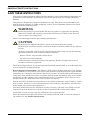
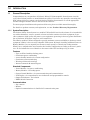
IMPORTANT SAFETY INSTRUCTIONS
SAVE THESE INSTRUCTIONS
This manual contains important instructions that should be closely followed during installation and
maintenance of this UPS unit and during the installation and replacement of Power and Battery
Modules.
This product is designed for Commercial/Industrial use only. This product is not intended for use
with life support and other U.S. FDA-designated “critical” devices. Maximum load must not exceed
that shown on the UPS rating label.
Observe the following precautions when working with batteries:
This UPS is designed for use on a properly grounded (earthed), 200/210 VAC, 50 or 60 Hz supply and
is to be installed by qualified personnel.
Electromagnetic Compatibility—The Nfinity™ UPS complies with the limits for a Class A digital
device, pursuant to Part 15 of FCC rules. These limits provide reasonable protection against harmful
interference in a commercial environment. This device generates, uses and radiates radio frequency
energy and, if not installed and used in accordance with the instruction manual, may cause harmful
interference to radio communications. Operating this device in a residential area is likely to cause
harmful interference which users must correct at their own expense.
Operate the UPS in an indoor environment only in an ambient temperature range of 32°F to +104°F
(0°C to +40°C). Install it in a clean environment, free from conductive contaminates, moisture, flam-
mable liquids, gases and corrosive substances.
Turn the UPS off and isolate the UPS before cleaning. Use only a soft cloth, never liquid or aerosol
cleaners. Keep the front and rear vents free of dust accumulation that could restrict airflow.
Never block or insert any object into the ventilation holes or other openings.
This UPS contains user replaceable modules. No attempts should be made to access the interior of
any module. See 4.3 - Module Replacement.
!
WARNING
Lethal voltages may be present within this unit even when it is apparently not operating.
Observe all cautions and warnings in this manual. Failure to do so MAY result in serious
injury or death. Never work alone.
!
CAUTION
DO NOT dispose of Battery Modules in a fire because the modules may explode.
DO NOT open or mutilate batteries; released electrolyte is harmful to skin and eyes and may
be toxic.
A battery can present a risk of electrical shock and high short-circuit current. The following
precautions should be observed when working on batteries:
• Remove watches, rings and other metal objects.
• Use tools with insulated handles.
Lead-acid batteries contain hazardous toxic materials. Handle, transport and recycle in
accordance with local regulations.

2
GLOSSARY OF SYMBOLS
Risk of electrical shock
Indicates caution followed by important instructions
AC input
AC output
Requests the user to consult the manual
Indicates the unit contains a valve-regulated lead acid
battery
Recycle
DC voltage
Equipment grounding conductor
Bonded to ground
AC voltage
OFF
ON
Standby
No telecommunication connection
Locked position
Unlocked position
Contact closure signals
Serial communications
i

Introduction
3
1.0 INTRODUCTION
1.1 General Description
Congratulations on your purchase of Liebert’s Nfinity™ Uninterruptible Power System. As with
every other Liebert product, we stand behind our quality. If you have any questions concerning this
UPS, please feel free to contact your local dealer or Liebert representative or call the appropriate
Technical Support number listed on the back of this manual.
To ensure proper installation and operation of this unit, please read this manual thoroughly.
For details on product warranty and registration, see 6.1 - Product Warranty Registration.
1.1.1 System Description
The Liebert Nfinity Power System is a modular UPS available in 8 & 12 bay frames. It is intended for
use with workstations, servers, network, telecom and other sensitive electronic equipment. It pro-
vides continuous, high-quality AC power to your equipment, protecting it from any power disturbance
due to blackouts, brownouts, surges or noise interference.
The Nfinity modular UPS was designed to provide maximum system availability to business-critical
equipment. Nfinity is also an easily adaptable UPS system. By simply installing additional Power or
Battery Modules, you can expand your current system capacity or extend your backup runtime.
Nfinity has a comprehensive user interface that enables configuration according to the user’s prefer-
ence. It also informs the user of details on the status of the UPS and keeps a log of events.
Features
• Up to 16 kVA of modular backup power
• Continuous power conditioning
• A user-friendly interface for custom configuration
• Continuous system monitoring
• Warning alarms and event logs
• Internal automatic & manual bypass
Standard Components
• Power Modules - for power conditioning
• Battery Modules - for backup power
• System Control Modules - for system monitoring and communications
• LCD Display - for comprehensive user indications and programmable controls
• Output Transformer - for isolation
• REPO Switch Connection
Communications
• Dry contacts
• RS-232
• Optional communications via Intellislot™ communication ports

Introduction
4
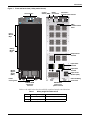
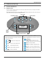
Figure 1 Front and back views (12 bay model shown)
Refer to the table below for size and fully populated weight considerations.
Table 1 Nfinity weight and dimensions
Model Max Weight - lb (kg) W x D x H - in. (mm)
8 bay 855 (388) 20 x 28 x 40 (508 x 711 x 1016)
12 bay 1176 (534) 20 x 28 x 53 (508 x 711 x 1346)
ESC
!
User Interface
Control
Switch (SW2)
Power
Module
Bays
Battery
Module
Bays
Manual
Bypass
Switch
(SW1)
Intake
Cooling Fans
DB-9
Communication
Ports
Output Power
Terminal
Input Power
Terminal
External Battery
Connection
REPO
Connection
Intellislot™
Communications Ports
Input Earth
Terminal
Input Circuit
Breaker (CB1)
BACK VIEW
with access
plates removed
FRONT VIEW
with bezels
removed

Introduction
5
1.2 Modes of Operation
Normal Mode
The Power Module rectifiers derive power from a utility AC source and supply regulated DC power to
the inverter. The module’s inverter regenerates precise AC power to supply the connected equipment.
The battery charger is in the Power Module and maintains a float-charge on the batteries.
Backup Mode
When AC utility fails, the connected equipment is supplied power by the inverter, which obtains
energy from the Battery Modules. The output power equipment will not be interrupted during the
failure or restoration of the AC utility source.
Auto Restart Mode
After a power outage and complete battery discharge, and once AC utility is restored, the UPS will
automatically restart and resume supplying power to connected equipment. This feature is enabled at
the factory, but can be disabled by the user. The user can also program two auto restart delay settings:
1. Battery capacity level (%)
2. Countdown timer
Bypass Mode
The bypass provides an alternate path for power to the connected equipment and operates in the fol-
lowing manner:
•Automatic
In the event of an internal fault or should the inverter overload capacity be exceeded, the UPS
performs an automatic transfer of the connected equipment from the inverter to the bypass
source.
• Manual
Should the UPS need to be taken out of service for limited maintenance or repair, manual activa-
tion of the bypass will cause an immediate transfer of the equipment from the inverter to the
bypass source.
OUTPUTINPUT
MANUAL
BYPASS
POWER
CONTROL
EMI
FILTER
POWER
MODULE(S)
OUTPUT &
BYPASS
CONTACTOR
SYSTEM
CONTROL
MODULE(S)
CONTROL
INTERFACE
USER
INTERFACE
BATTERY
MODULE(S)
COMMUNICATIONS
OUTPUT
TRANSFORMER

Introduction
6
1.3 Major Components
The following is a general description of each compo-
nent and its functions. Please review this section
carefully, as it will give you a better understanding as
to how the Nfinity operates.
1.3.1 Unit Frame
The front of the Nfinity consists of a series of plastic
bezels. By grasping these bezels from the left and
right sides and pulling straight out, you can remove
the bezel to reveal the Battery / Power Module bays.
The bottom bezel covers the internal cooling fans and
the manual bypass switch.
The User Interface Module is located above the
Power / Battery Module bays for easy access. By mov-
ing the User Interface and setting it on top of the
frame, you will see the system control module bays.
1.3.2 User Interface Module
The User Interface Module is the primary source of
communication between the UPS and the user. From
the interface, the user can:
• View the status of the UPS
• Custom configure the system
• Review the event log to assist with
troubleshooting
• Enable/disable the output power
• Silence the audible alarm
• Manually transfer the unit to bypass
For a more detailed explanation on how to operate the
User Interface Module, see 3.1 - Controls and Indi-
cators.
1.3.3 System Control Module
The System Control Module is the communications
backbone of the UPS. It gathers input from all mod-
ules and processes the data to control the operation of
the system — including monitoring the condition of
each module. An optional redundant System Control
Module can be installed to provide full system func-
tionality (operation and communication).
Under normal operation, the Status LED (green) will
blink and the Fault LED (yellow) will be off. For any
condition other than this, check 4.0 - Troubleshoot-
ing.
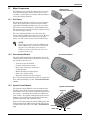
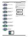
NOTE
In the figure at right, the Power Module and
Battery Module are extended for illustration
purposes only. Extending more than one
module at a time could cause the unit to be
top-heavy and/or tip.
Nfinity’s frame
with bezels removed
User Interface Module
Fault LED
Status LED
Lever
Fasteners
System Control Module

Introduction
7
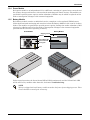
1.3.4 Power Module
Each power module is an independent 4 kVA, 2.8kW unit, consisting of a power factor corrected recti-
fier, battery charger and inverter, with associated monitoring and control circuitry. The modules are
paralleled to provide greater capacity and/or redundancy. Modules may be added or replaced on-line
with no interruption or danger to the connected equipment.
1.3.5 Battery Module
Each battery module contains 10 individual 12-volt, 9 amp hour, valve-regulated (VRLA) battery
blocks with associated monitoring and controls to isolate the Battery Module in the event of a battery
failure. The modules are paralleled to provide greater capacity, backup time and/or redundancy. Mod-
ules may be added or replaced on-line with no interruption or danger to the connected equipment,
provided that the UPS is not operating on battery.
Under normal operation, the Green Status LED will blink continuously and the Yellow Fault LED
will be off. For any condition other than this, check 4.0 - Troubleshooting.
NOTE
Nfinity is shipped with each battery module secured to the frame by two shipping screws. These
screws should be removed prior to start-up.
Power Module Battery Module
Shipping screws
FRONTFRONT
Fastener
Green Status LED
Yellow Fault LED
Cooling Fan
Lever

Installation
8
2.0 INSTALLATION
2.1 Inspection
Upon receiving the UPS, examine the packaging for any signs of mishandling or damage. If any dam-
age is noted, call your local dealer or Liebert representative and/or notify your carrier.
2.1.1 Environment
2.1.2 Required Setup Equipment
The tools below are required to properly set up your UPS:
• Pallet jack
• 1/2" (13mm) ratchet or wrench
• Torque wrench (in-lb)
• Flathead screwdriver
• #2 Phillips screwdriver
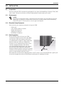
2.1.3 Site Preparation
When deciding where to locate your UPS,
consider the weight and size of the unit. Make
sure that the structural integrity of the floor
can withstand the weight of a fully loaded unit.
Check to make sure that your UPS will be
located in a well-ventilated area with at least
12 inches (305mm) behind it. The UPS is
air-cooled utilizing internal fans. Air is drawn
into the front of the UPS and is exhausted
through ventilation grilles in the back. It should
also have at least 36 inches (915mm) in front in
order to change modules when necessary.
The unit frame is bolted to the shipping pallet to ensure safety. It is recommended that a pallet jack
be used to transport the unit to its operating location (prior to unbolting the unit).
NOTE
Operating in temperatures above 77°F (25°C) will reduce battery life. The UPS environment
must be free of conductive contaminants and excessive moisture (water and condensation),
flammable vapors, chemical fumes, corrosive gases and liquids.
36"
(915 mm)
12"
(305mm)

Installation
9
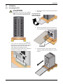
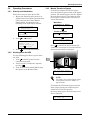
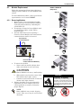
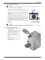
2.2 Unloading
2.2.1 Unloading the UPS
!
CAUTION
2. Remove the metal ramp from the bottom of
the UPS.
This UPS is very heavy (see weight in
Table 1). At least two people should
assist in unloading it from the pallet.
3. Fit the ramp flange in the slot in the rear
of the pallet (back of unit) as shown below.
1. Use a ratchet or wrench, 1/2" (13mm), to
remove the four mounting bolts from the
front and rear pallet brackets. Remove the
mounting brackets from the pallet and
UPS. Keep the brackets for future
transportation of the UPS or for additional
stability of the UPS once in place.
4. Using two people, slowly move the UPS
down the ramp until the UPS is on a level
surface.
Pull ramp out from
under front of unit,
then turn ramp over
Fit ramp in
rear of pallet

Installation
10
5. Once the UPS is in the desired location, adjust the leveling feet to secure its position.
2.2.2 Stationary Mounting
Additional stability can be added by bolting the mounting brackets (used in shipping) to the floor, as
shown below left.
For greater stability, use a higher-grade bolt. Refer to the dimensions above right when drilling holes
for stationary mounting.
1/2" (13mm)
28"
(711mm)
5/16" (7.94mm)
diameter - in six
places
Optional Stationary
Mounting Dimensions
Center Line
4.75"
(120mm)
4.75"
(120mm)
Shipping Brackets Used
for Stationary Mounting

Installation
11
2.3 Cable Installation
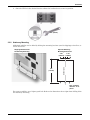
2.3.1 Wiring Preparation
Removing the Cover Plates
On the back
of the UPS,
cover plates
are over the
input and
output
terminals, as
shown at
right. Keep
screws and
plates to one
side.
Customer-Provided Overcurrent Protection
A branch rated overcurrent protection device (cir-
cuit breaker or fused disconnect switch) must be
installed for the AC input.
If the start-up is on bypass, the UPS has a six-
cycle inrush current that is up to 20 times the
rated output current. This must be taken into
account when selecting the overload protection
device at the AC input supply distribution point.
To avoid random tripping on start-up, it is recom-
mended that the AC input supply be protected
with a circuit breaker capable of withstanding
this initial inrush.
This UPS is fitted with EMI suppression filters.
Earth leakage current is less than 40mA. Tran-
sient and steady state earth leakage currents may
occur when starting the equipment. This should
be taken into account when selecting ground cur-
rent detection devices, as the earth leakage cur-
rents of both the UPS and load will be carried.
Input and output cables must be run in separate
conduits.
!
WARNING
Please read this section thoroughly
before attempting to install wiring to
this unit.
This UPS should be installed by a
qualified / certified electrician.
Remove Cover Plates

Installation
12
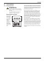
Input Wiring (TB1)
To connect the input wiring, follow these steps:
1. Locate the input wiring access, remove the knockout and
pull the three input wires through it, allowing some slack
for installation.
2. Secure the conduit to the rear panel of the UPS.
3. Input Power cables connect to screw terminals on the
Input Terminal Block located to the right of the Bypass
Voltage Terminal. Connect the wires to the block
connections as shown below. Using a torque wrench, turn
the screws clockwise until tightened to the proper torque
value (28 in-lb). Insert the ground wire through the
grounding lug and tighten it to the proper torque value
(120 in-lb).
Grounding Conductor Installation
An insulated grounding conductor must be identical or larger
in size, insulation material, and thickness as the grounded
and ungrounded branch circuit supply conductors. This cable
must be green with or without one or more yellow stripes and
is to be installed as part of the branch circuit that supplies
the unit or system.
The grounding conductor is to be grounded to earth at the
service equipment or, if supplied by a separately derived sys-
tem, at the supply transformer or generator set.
Output Wiring (TB3)
Refer to the chart below and the diagram at right
when configuring the output wiring.
Voltage 105 210
Between terminals 1 & 3,
2 & 3
1 & 2
Use only the connections listed above. Other connections will
produce nonstandard voltages.
NOTE
The Nfinity UPS contains an isolation
transformer that generates a neutral
conductor for the connected equipment.
The UPS is a separately derived source
and contains a neutral to ground bonding
jumper. A grounding electrode conductor
(GEC) must be installed in accordance
with national and local wiring codes and
regulations.
TB1
L1
L2
2
1
Note the Neutral / Earth
jumper on the terminal
above
105V
210V
105V

Installation
13
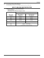
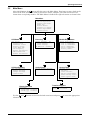
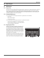
2.3.2 Connecting to External Panel Boards
The following instructions are also shipped attached to the rear of the unit.
INPUT CABLING AND PROTECTION
Table Below Applies to 4-16kVA Scalable Systems:
Stand-alone UPS or
UPS equipped with a Maintenance Bypass Cabinet
Max. System
Load Rating
Input Voltage – 200/210VAC
Max. Current
in UPS mode
Recommended
Input Protection
Circuit Breaker
4kVA 18 amps 50 amps
8kVA
36 amps 50 amps
12kVA 53 amps 75 amps
16kVA
70 amps 100 amps
Terminal
Block
Details
Maximum: 35mm
2
(2AWG)
Minimum: 16mm
2
(6AWG)
Torque Rating: 2.5-3.0Nm (22-26 in/lbs)

Installation
14
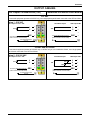
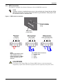
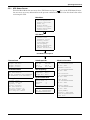
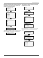
OUTPUT CABLING
UPS Output Terminal Block (TB3) Connection to External Panel Boards
210 VAC
If connected equipment operates at 210VAC only, use a single-phase panel board connected to the UPS as follows.
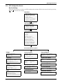
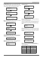
210VAC and/or 105VAC
If connected equipment operates at 210VAC only or 105VAC only or is a combination of both, use a single-phase
panel board connected to the UPS as follows.
1
2
3
4
Setup 1 - 210 VAC
210
Grounding Electrode Conductor
(Field connection must be made)
L
L
GEC
Max output current = 76A
Connected Equipment
Ground
210
UPS Output TB3Panel Board Input
Grounding Electrode Conductor
(Field connection must be made)
1
2
3
4
L
L
GEC
G
1
2
3
4
Setup 2 - 210/105 VAC
Grounding Electrode Conductor
(Field connection must be made)
Max output current = 76A
L
L
GEC
Connected Equipment
Ground
210
210
105
105
UPS Output TB3Panel Board Input
1
2
3
4
N
L
L
G
Grounding Electrode Conductor
(Field connection must be made)
GEC

Installation
15
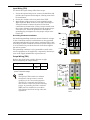
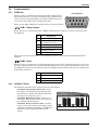
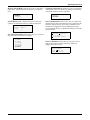
2.3.3 REPO Connection
The Nfinity is equipped with a Remote Emergency Power Off (REPO) connection.
Figure 2 REPO switch connections
NOTE
A jumper is factory installed between pins 1 & 2 to disable the Control Switch (SW2).
This will prevent the unit from being started during installation. This jumper must
be removed in order to start the unit.
!
CAUTION
To maintain safety, Signal Edge Low Voltage (SELV) barriers, and electromagnetic
compatibility, signal cables should be segregated and run separately from power cables.
NOTE
Remove jumper before wiring.
If the installation does not
require connection to a REPO
system, the jumper must be
removed.
1234
Key to REPO switch connections
1. 24 V DC, 50mA
2. Sense
3. Sense
4. Ground
REPO connections
for normally open
switch system
REPO jumper
connected
as shipped
REPO connections
for normally closed
switch system (fail-safe)
Hanger for cable-tie
to strain relief REPO
wiring
REPO switch
on rear of unit
1234 1234

Installation
16
2.4 Communications
2.4.1 COM Ports
Nfinity is able to communicate through multiple communication
ports simultaneously. Use only Liebert-provided communication
cards. Connect only Signal Edge Low Voltage (SELV)/Class 2 cir-
cuits when connecting to any communication port.
There are two DB-9 COM ports available on the rear of the Nfinity.
COM1 - Relay Contacts
Relay contacts are available through a DB-9F communications connector. Contact closure provides
the following:
These contacts are rated 48 VDC, 1 amp maximum and are compatible with Liebert MultiLink™
software.
COM2 - Serial
Nfinity is able to communicate via Liebert proprietary protocol. This communication port can be used
for serial communication with Liebert MultiLink software. For more detailed information, please see
the MultiLink software documentation on the CD shipped with the Nfinity. The pin-out configuration
of the DB-9 connector is:
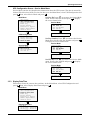
2.4.2 Intellislot™ Ports
The following communication cards may be used with Nfinity:
• Intellislot OpenComms Web Card—allows
the Nfinity to communicate intelligently with
your Ethernet network. The OpenComms Web
Card must be installed in port 1.
• Intellislot MultiPort4 cards—allows up to
four client computer systems to monitor the sta-
tus of Nfinity simultaneously.
• Intellislot Relay Contacts cards—provides
contact closures for remote monitoring of alarm
conditions; On Battery, On Bypass, Low Battery,
Summary Alarm, UPS Fault and On UPS
signals.
Pin Assignment
1 Low Battery (normally open)
4 UPS shutdown in battery mode
(5-12 V DC for 1.5 sec)
5 Common
7 Low Battery (common)
8 On Battery (common)
9 On Battery (normally open)
Pin Assignment
2 Transmit Data
3 Receive Data
5 Common
54321
6789
Pin Assignment
Port 1 Port 2 Port 3 Port 4
COM 1 COM 2
Page is loading ...
Page is loading ...
Page is loading ...
Page is loading ...
Page is loading ...
Page is loading ...
Page is loading ...
Page is loading ...
Page is loading ...
Page is loading ...
Page is loading ...
Page is loading ...
Page is loading ...
Page is loading ...
Page is loading ...
Page is loading ...
Page is loading ...
Page is loading ...
Page is loading ...
Page is loading ...
Page is loading ...
Page is loading ...
Page is loading ...
Page is loading ...
-
 1
1
-
 2
2
-
 3
3
-
 4
4
-
 5
5
-
 6
6
-
 7
7
-
 8
8
-
 9
9
-
 10
10
-
 11
11
-
 12
12
-
 13
13
-
 14
14
-
 15
15
-
 16
16
-
 17
17
-
 18
18
-
 19
19
-
 20
20
-
 21
21
-
 22
22
-
 23
23
-
 24
24
-
 25
25
-
 26
26
-
 27
27
-
 28
28
-
 29
29
-
 30
30
-
 31
31
-
 32
32
-
 33
33
-
 34
34
-
 35
35
-
 36
36
-
 37
37
-
 38
38
-
 39
39
-
 40
40
-
 41
41
-
 42
42
-
 43
43
-
 44
44


Liebert Nfinity User manual
- Type
- User manual
- This manual is also suitable for
Ask a question and I''ll find the answer in the document
Finding information in a document is now easier with AI
Related papers
-
Liebert Nfinity User manual
-
Liebert Nfinity User manual
-
-
-
-
-
-
-
-
Other documents
-
Emerson 240V User manual
-
-
-
-
-
-
 PROGRESSIVE INDUSTRIES HW30C User manual
-
-
-
Big Ass Fans Essence User guide
