Yamaha 2011 VMAX Owner's manual
- Category
- Motorcycles
- Type
- Owner's manual

DIC183
2S3-28199-12
VMX17A(C)
OWNER’S MANUAL
Read this manual carefully before operating this vehicle.
LIT-11626-24-26

EAU10042
Read this manual carefully before operating this vehicle. This manual should stay with this vehicle if it is sold.
U2S312E0.book Page 1 Thursday, June 3, 2010 9:43 AM

INTRODUCTION
EAU10083
Congratulations on your purchase of the Yamaha VMX17A(C). This model is the result of Yamaha’s vast experience in the
production of fine sporting, touring, and pacesetting racing machines. It represents the high degree of craftsmanship and
reliability that have made Yamaha a leader in these fields.
This manual will give you an understanding of the operation, inspection, and basic maintenance of this motorcycle. If you
have any questions concerning the operation or maintenance of your motorcycle, please consult a Yamaha dealer.
The design and manufacture of this Yamaha motorcycle fully comply with the emissions standards for clean air applicable at
the date of manufacture. Yamaha has met these standards without reducing the performance or economy of operation of the
motorcycle. To maintain these high standards, it is important that you and your Yamaha dealer pay close attention to the
recommended maintenance schedules and operating instructions contained within this manual.
Yamaha continually seeks advancements in product design and quality. Therefore, while this manual contains the most cur-
rent product information available at the time of printing, there may be minor discrepancies between your motorcycle and this
manual. If there is any question concerning this manual, please consult a Yamaha dealer.
WARNING
EWA10011
Please read this manual and the “YOU AND YOUR MOTORCYCLE: RIDING TIPS” booklet carefully before operating
this motorcycle. Do not attempt to operate this motorcycle until you have attained adequate knowledge of its con-
trols and operating features. Regular inspections and careful maintenance, along with good operating techniques,
will help ensure that you safely enjoy the capabilities and reliability of this motorcycle.
U2S312E0.book Page 1 Thursday, June 3, 2010 9:43 AM

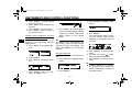
IMPORTANT MANUAL INFORMATION
EAU10132
Particularly important information is distinguished in this manual by the following notations:
This is the safety alert symbol. It is used to alert you to potential personal injury
hazards. Obey all safety messages that follow this symbol to avoid possible injury
or death.
A WARNING indicates a hazardous situation which, if not avoided, could result in
death or serious injury.
A NOTICE indicates special precautions that must be taken to avoid damage to the
vehicle or other property.
A TIP provides key information to make procedures easier or clearer.
WARNING
NOTICE
TIP
U2S312E0.book Page 1 Thursday, June 3, 2010 9:43 AM

IMPORTANT MANUAL INFORMATION
EAU10193
VMX17A(C)
OWNER’S MANUAL
©2010 by Yamaha Motor Corporation, U.S.A.
1st edition, May 2010
All rights reserved.
Any reprinting or unauthorized use
without the written permission of
Yamaha Motor Corporation, U.S.A.
is expressly prohibited.
Printed in Japan.
P/N LIT-11626-24-26
U2S312E0.book Page 2 Thursday, June 3, 2010 9:43 AM

TABLE OF CONTENTS
LOCATION OF IMPORTANT
LABELS .............................................1-1
SAFETY INFORMATION ..................2-1
DESCRIPTION ..................................3-1
Left view ..........................................3-1
Right view........................................3-2
Controls and instruments.................3-3
INSTRUMENT AND CONTROL
FUNCTIONS .......................................4-1
Main switch/steering lock ................4-1
Indicator lights and warning
lights ............................................4-2
Speedometer unit ...........................4-5
Multi-function display ......................4-6
Handlebar switches ......................4-14
Clutch lever ...................................4-15
Shift pedal .....................................4-16
Brake lever ...................................4-16
Brake pedal ..................................4-17
ABS ..............................................4-17
Fuel tank cap ................................4-18
Fuel ...............................................4-19
Fuel tank breather/overflow
hose ..........................................4-21
Catalytic converters ......................4-21
Seats ............................................4-22
Adjusting the front fork ..................4-23
Adjusting the shock absorber
assembly ................................... 4-25
Luggage strap holders .................4-27
EXUP system ............................... 4-27
Sidestand ..................................... 4-28
Ignition circuit cut-off system ........ 4-28
FOR YOUR SAFETY –
PRE-OPERATION CHECKS ............. 5-1
OPERATION AND IMPORTANT
RIDING POINTS................................. 6-1
Starting the engine ......................... 6-1
Shifting ........................................... 6-2
Engine break-in .............................. 6-3
Parking ........................................... 6-4
PERIODIC MAINTENANCE AND
ADJUSTMENT ................................... 7-1
Owner’s tool kit ............................... 7-2
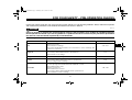
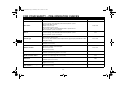
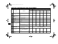
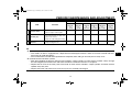
Periodic maintenance chart for the
emission control system ............. 7-3
General maintenance and
lubrication chart .......................... 7-5
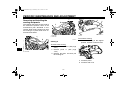
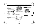
Removing and installing the
cowling and panels ..................... 7-9
Checking the spark plugs ............. 7-11
Canister (for California only) ........ 7-12
Engine oil and oil filter cartridge ... 7-12
Final gear oil ................................. 7-15
Coolant ......................................... 7-18
Air filter element ........................... 7-20
Checking the engine idling
speed ........................................ 7-21
Checking the throttle grip free
play ........................................... 7-21
Valve clearance ........................... 7-21
Tires ............................................. 7-22
Cast wheels ................................. 7-24
Clutch lever .................................. 7-24
Checking the brake lever free
play ........................................... 7-25
Brake light switches ..................... 7-25
Checking the front and rear brake
pads .......................................... 7-26
Checking the brake fluid level ...... 7-26
Changing the brake and clutch
fluids ......................................... 7-27
Checking and lubricating the
cables ....................................... 7-28
Checking and lubricating the
throttle grip and cable ............... 7-28
Checking and lubricating the
brake and shift pedals .............. 7-28
Checking and lubricating the
brake and clutch levers ............ 7-29
Checking and lubricating the
sidestand .................................. 7-30
Lubricating the swingarm
pivots ........................................ 7-30
Checking the front fork ................. 7-30
Checking the steering .................. 7-31
U2S312E0.book Page 1 Thursday, June 3, 2010 9:43 AM

TABLE OF CONTENTS
Checking the wheel bearings .......7-31
Battery ..........................................7-32
Replacing the fuses ......................7-34
Replacing the headlight bulb ........7-36
Tail/brake light ..............................7-37
Replacing a turn signal light
bulb ...........................................7-38
Replacing a license plate light
bulb ...........................................7-38
Replacing the auxiliary light
bulb ...........................................7-40
Supporting the motorcycle ............7-40
Troubleshooting ............................7-41
Troubleshooting charts .................7-42
MOTORCYCLE CARE AND
STORAGE ..........................................8-1
Matte color caution .........................8-1
Care ................................................8-1
Storage ...........................................8-4
SPECIFICATIONS .............................9-1
CONSUMER INFORMATION...........10-1
Identification numbers ..................10-1
Reporting safety defects ...............10-3
Motorcycle noise regulation ..........10-4
Maintenance record ......................10-5
YAMAHA MOTOR
CORPORATION, U.S.A.
STREET AND ENDURO
MOTORCYCLE LIMITED
WARRANTY ............................. 10-7
YAMAHA EXTENDED SERVICE
(Y.E.S.) ..................................... 10-9
U2S312E0.book Page 2 Thursday, June 3, 2010 9:43 AM

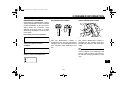
LOCATION OF IMPORTANT LABELS
1-1
1
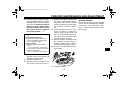
EAU10384
Read and understand all of the labels on your vehicle. They contain important information for safe and proper operation of
your vehicle. Never remove any labels from your vehicle. If a label becomes difficult to read or comes off, a replacement label
is available from your Yamaha dealer.
1 23
45
U2S312E0.book Page 1 Thursday, June 3, 2010 9:43 AM

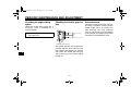
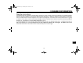
LOCATION OF IMPORTANT LABELS
1-2
1
This unit contains high pressure nitrogen gas.
Mishandling can cause explosion.
Read owner's manual for instructions.
Do not incinerate, puncture or open.
4AA-22259-80
WARNING
BEFORE YOU OPERATE THIS VEHICLE, READ
THE OWNER’S MANUAL AND ALL LABELS.
ALWAYS WEAR AN APPROVED MOTORCYCLE
HELMET, eye protection, and protective clothing.
5GK-2118K-00
PREMIUM
UNLEADED GASOLINE ONLY
91 Min.
Pump
Octane (R+M) / 2
5PW-2415E-11
4B5-21686-00
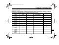
TIRE INFORMATION
Cold tire normal pressure should be set
as follows.
• Up to 90 kg (198 lbs) load
FRONT
REAR
: 250 kPa, (2.50 kgf/cm²), 36 psi
: 290 kPa, (2.90 kgf/cm²), 42 psi
• 90kg (198 lbs) ~ maximum load
FRONT
REAR
: 250 kPa, (2.50 kgf/cm²), 36 psi
: 290 kPa, (2.90 kgf/cm²), 42 psi
2S3-21668-00
5
1
3
2 California Only
4
U2S312E0.book Page 2 Thursday, June 3, 2010 9:43 AM

2-1
2
SAFETY INFORMATION
EAU10287
Be a Responsible Owner
As the vehicle’s owner, you are respon-
sible for the safe and proper operation
of your motorcycle.
Motorcycles are single-track vehicles.
Their safe use and operation are de-
pendent upon the use of proper riding
techniques as well as the expertise of
the operator. Every operator should
know the following requirements before
riding this motorcycle.
He or she should:
● Obtain thorough instructions from
a competent source on all aspects
of motorcycle operation.
● Observe the warnings and mainte-
nance requirements in this Own-
er’s Manual.
● Obtain qualified training in safe
and proper riding techniques.
● Obtain professional technical ser-
vice as indicated in this Owner’s
Manual and/or when made neces-
sary by mechanical conditions.
Safe Riding
Perform the pre-operation checks each
time you use the vehicle to make sure it
is in safe operating condition. Failure to
inspect or maintain the vehicle properly
increases the possibility of an accident
or equipment damage. See page 5-1
for a list of pre-operation checks.
● This motorcycle is designed to car-
ry the operator and a passenger.
● The failure of motorists to detect
and recognize motorcycles in traf-
fic is the predominating cause of
automobile/motorcycle accidents.
Many accidents have been caused
by an automobile driver who did
not see the motorcycle. Making
yourself conspicuous appears to
be very effective in reducing the
chance of this type of accident.
Therefore:
• Wear a brightly colored jacket.
• Use extra caution when you are
approaching and passing
through intersections, since in-
tersections are the most likely
places for motorcycle accidents
to occur.
• Ride where other motorists can
see you. Avoid riding in another
motorist’s blind spot.
● Many accidents involve inexperi-
enced operators. In fact, many op-
erators who have been involved in
accidents do not even have a cur-
rent motorcycle license.
• Make sure that you are qualified
and that you only lend your mo-
torcycle to other qualified opera-
tors.
• Know your skills and limits.
Staying within your limits may
help you to avoid an accident.
• We recommend that you prac-
tice riding your motorcycle
where there is no traffic until you
have become thoroughly famil-
iar with the motorcycle and all of
its controls.
● Many accidents have been caused
by error of the motorcycle opera-
tor. A typical error made by the op-
erator is veering wide on a turn
U2S312E0.book Page 1 Thursday, June 3, 2010 9:43 AM

SAFETY INFORMATION
2-2
2
due to excessive speed or under-
cornering (insufficient lean angle
for the speed).
• Always obey the speed limit and
never travel faster than warrant-
ed by road and traffic conditions.
• Always signal before turning or
changing lanes. Make sure that
other motorists can see you.
● The posture of the operator and
passenger is important for proper
control.
• The operator should keep both
hands on the handlebar and
both feet on the operator foot-
rests during operation to main-
tain control of the motorcycle.
• The passenger should always
hold onto the operator, the seat
strap or grab bar, if equipped,
with both hands and keep both
feet on the passenger footrests.
Never carry a passenger unless
he or she can firmly place both
feet on the passenger footrests.
● Never ride under the influence of
alcohol or other drugs.
● This motorcycle is designed for on-
road use only. It is not suitable for
off-road use.
Protective Apparel
The majority of fatalities from motorcy-
cle accidents are the result of head in-
juries. The use of a safety helmet is the
single most critical factor in the preven-
tion or reduction of head injuries.
● Always wear an approved helmet.
● Wear a face shield or goggles.
Wind in your unprotected eyes
could contribute to an impairment
of vision that could delay seeing a
hazard.
● The use of a jacket, heavy boots,
trousers, gloves, etc., is effective in
preventing or reducing abrasions
or lacerations.
● Never wear loose-fitting clothes,
otherwise they could catch on the
control levers, footrests, or wheels
and cause injury or an accident.
● Always wear protective clothing
that covers your legs, ankles, and
feet. The engine or exhaust sys-
tem become very hot during or af-
ter operation and can cause burns.
● A passenger should also observe
the above precautions.
Avoid Carbon Monoxide Poisoning
All engine exhaust contains carbon
monoxide, a deadly gas. Breathing car-
bon monoxide can cause headaches,
dizziness, drowsiness, nausea, confu-
sion, and eventually death.
Carbon Monoxide is a colorless, odor-
less, tasteless gas which may be
present even if you do not see or smell
any engine exhaust. Deadly levels of
carbon monoxide can collect rapidly
and you can quickly be overcome and
unable to save yourself. Also, deadly
levels of carbon monoxide can linger
for hours or days in enclosed or poorly
ventilated areas. If you experience any
symptoms of carbon monoxide poison-
ing, leave the area immediately, get
fresh air, and SEEK MEDICAL TREAT-
MENT.
● Do not run engine indoors. Even if
you try to ventilate engine exhaust
with fans or open windows and
doors, carbon monoxide can rap-
idly reach dangerous levels.
U2S312E0.book Page 2 Thursday, June 3, 2010 9:43 AM

SAFETY INFORMATION
2-3
2
● Do not run engine in poorly venti-
lated or partially enclosed areas
such as barns, garages, or car-
ports.
● Do not run engine outdoors where
engine exhaust can be drawn into
a building through openings such
as windows and doors.
Loading
Adding accessories or cargo to your
motorcycle can adversely affect stabili-
ty and handling if the weight distribution
of the motorcycle is changed. To avoid
the possibility of an accident, use ex-
treme caution when adding cargo or
accessories to your motorcycle. Use
extra care when riding a motorcycle
that has added cargo or accessories.
Here, along with the information about
accessories below, are some general
guidelines to follow if loading cargo to
your motorcycle:
The total weight of the operator, pas-
senger, accessories and cargo must
not exceed the maximum load limit.
Operation of an overloaded vehicle
could cause an accident.
When loading within this weight limit,
keep the following in mind:
● Cargo and accessory weight
should be kept as low and close to
the motorcycle as possible. Se-
curely pack your heaviest items as
close to the center of the vehicle as
possible and make sure to distrib-
ute the weight as evenly as possi-
ble on both sides of the motorcycle
to minimize imbalance or instabili-
ty.
● Shifting weights can create a sud-
den imbalance. Make sure that ac-
cessories and cargo are securely
attached to the motorcycle before
riding. Check accessory mounts
and cargo restraints frequently.
• Properly adjust the suspension
for your load (suspension-ad-
justable models only), and
check the condition and pres-
sure of your tires.
• Never attach any large or heavy
items to the handlebar, front
fork, or front fender. These
items, including such cargo as
sleeping bags, duffel bags, or
tents, can create unstable han-
dling or a slow steering re-
sponse.
● This vehicle is not designed to
pull a trailer or to be attached to
a sidecar.
Genuine Yamaha Accessories
Choosing accessories for your vehicle
is an important decision. Genuine
Yamaha accessories, which are avail-
able only from a Yamaha dealer, have
been designed, tested, and approved
by Yamaha for use on your vehicle.
Many companies with no connection to
Yamaha manufacture parts and acces-
sories or offer other modifications for
Yamaha vehicles. Yamaha is not in a
position to test the products that these
aftermarket companies produce.
Therefore, Yamaha can neither en-
dorse nor recommend the use of ac-
cessories not sold by Yamaha or
Maximum load:
VMX17A 190 kg (419 lb)
VMX17AC 189 kg (417 lb)
U2S312E0.book Page 3 Thursday, June 3, 2010 9:43 AM

SAFETY INFORMATION
2-4
2
modifications not specifically recom-
mended by Yamaha, even if sold and
installed by a Yamaha dealer.
Aftermarket Parts, Accessories, and
Modifications
While you may find aftermarket prod-
ucts similar in design and quality to
genuine Yamaha accessories, recog-
nize that some aftermarket accessories
or modifications are not suitable be-
cause of potential safety hazards to you
or others. Installing aftermarket prod-
ucts or having other modifications per-
formed to your vehicle that change any
of the vehicle’s design or operation
characteristics can put you and others
at greater risk of serious injury or death.
You are responsible for injuries related
to changes in the vehicle.
Keep the following guidelines in mind,
as well as those provided under “Load-
ing” when mounting accessories.
● Never install accessories or carry
cargo that would impair the perfor-
mance of your motorcycle. Care-
fully inspect the accessory before
using it to make sure that it does
not in any way reduce ground
clearance or cornering clearance,
limit suspension travel, steering
travel or control operation, or ob-
scure lights or reflectors.
• Accessories fitted to the handle-
bar or the front fork area can
create instability due to improper
weight distribution or aerody-
namic changes. If accessories
are added to the handlebar or
front fork area, they must be as
lightweight as possible and
should be kept to a minimum.
• Bulky or large accessories may
seriously affect the stability of
the motorcycle due to aerody-
namic effects. Wind may at-
tempt to lift the motorcycle, or
the motorcycle may become un-
stable in cross winds. These ac-
cessories may also cause
instability when passing or being
passed by large vehicles.
• Certain accessories can dis-
place the operator from his or
her normal riding position. This
improper position limits the free-
dom of movement of the opera-
tor and may limit control ability,
therefore, such accessories are
not recommended.
● Use caution when adding electri-
cal accessories. If electrical acces-
sories exceed the capacity of the
motorcycle’s electrical system, an
electric failure could result, which
could cause a dangerous loss of
lights or engine power.
Aftermarket Tires and Rims
The tires and rims that came with your
motorcycle were designed to match the
performance capabilities and to provide
the best combination of handling, brak-
ing, and comfort. Other tires, rims, siz-
es, and combinations may not be
appropriate. Refer to page 7-22 for tire
specifications and more information on
replacing your tires.
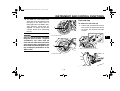
Transporting the Motorcycle
Be sure to observe following instruc-
tions before transporting the motorcy-
cle in another vehicle.
● Remove all loose items from the
motorcycle.
U2S312E0.book Page 4 Thursday, June 3, 2010 9:43 AM

SAFETY INFORMATION
2-5
2
● Check that the fuel cock (if
equipped) is in the “OFF” position
and that there are no fuel leaks.
● Point the front wheel straight
ahead on the trailer or in the truck
bed, and choke it in a rail to pre-
vent movement.
● Shift the transmission in gear (for
models with a manual transmis-
sion).
● Secure the motorcycle with tie-
downs or suitable straps that are
attached to solid parts of the mo-
torcycle, such as the frame or up-
per front fork triple clamp (and not,
for example, to rubber-mounted
handlebars or turn signals, or parts
that could break). Choose the lo-
cation for the straps carefully so
the straps will not rub against
painted surfaces during transport.
● The suspension should be com-
pressed somewhat by the tie-
downs, if possible, so that the mo-
torcycle will not bounce excessive-
ly during transport.
U2S312E0.book Page 5 Thursday, June 3, 2010 9:43 AM

DESCRIPTION
3-1
3
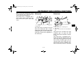
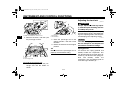
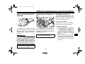
EAU10410
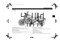
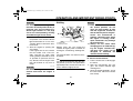
Left view
1
4
567 8
11 910
12
131415
2
3
16
1. Headlight (page 7-36)
2. Front fork spring preload adjusting bolt (page 4-23)
3. Front fork rebound damping force adjusting knob (page 4-23)
4. Battery (page 7-32)
5. Owner’s tool kit (page 7-2)
6. Fuel tank cap (page 4-18)
7. Shock absorber assembly spring preload adjusting knob (page 4-25)
8. Luggage strap holder (page 4-27)
9. Final gear oil check bolt (page 7-15)
10.Final gear oil drain bolt (page 7-15)
11.Shock absorber assembly rebound damping force adjusting knob
(page 4-25)
12.Sidestand (page 4-28)
13.Shift pedal (page 4-16)
14.Engine oil drain bolt (page 7-12)
15.Engine oil filter cartridge (page 7-12)
16.Front fork compression damping force adjusting screw (page 4-23)
U2S312E0.book Page 1 Thursday, June 3, 2010 9:43 AM

DESCRIPTION
3-2
3
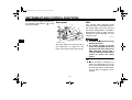
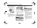
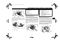
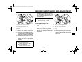
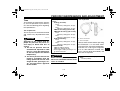
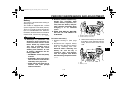
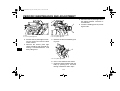
EAU10420
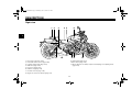
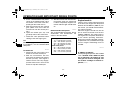
Right view
12 4 6
7
53
911
8
10
1. Passenger seat (page 4-22)
2. Rear brake fluid reservoir (page 7-26)
3. Luggage strap holder (page 4-27)
4. Rider seat (page 4-22)
5. Fuse box 1 (page 7-34)
6. Radiator cap (page 7-18)
7. Coolant reservoir (page 7-18)
8. Engine oil level check window (page 7-12)
9. Brake pedal (page 4-17)
10.Fuse box 2 (page 7-34)
11.Shock absorber assembly compression damping force adjusting knob
(page 4-25)
U2S312E0.book Page 2 Thursday, June 3, 2010 9:43 AM

DESCRIPTION
3-3
3
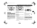
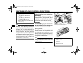
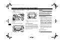
EAU10430
Controls and instruments
123 4 67 8
910
11
5
1. Clutch lever (page 4-15)
2. Left handlebar switches (page 4-14)
3. Clutch fluid reservoir (page 7-26)
4. Speedometer unit (page 4-5)
5. Shift timing indicator light (page 4-4)
6. Front brake fluid reservoir (page 7-26)
7. Right handlebar switches (page 4-14)
8. Brake lever (page 4-16)
9. Throttle grip (page 7-21)
10.Multi-function display (page 4-6)
11.Main switch/steering lock (page 4-1)
U2S312E0.book Page 3 Thursday, June 3, 2010 9:43 AM

INSTRUMENT AND CONTROL FUNCTIONS
4-1
4
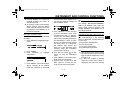
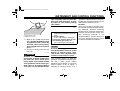
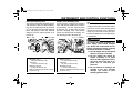
EAU10460
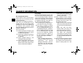
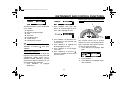
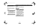
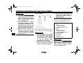
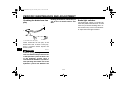
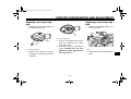
Main switch/steering lock
The main switch/steering lock controls
the ignition and lighting systems, and is
used to lock the steering. The various
positions are described below.
EAU39242
ON
All electrical circuits are supplied with
power, and the meter lighting, taillight,
license plate light, auxiliary light and
position lights come on, and the engine
can be started. The key cannot be re-
moved.
TIP
The headlight comes on automatically
when the engine is started and stays on
until the key is turned to “OFF”, even if
the engine stalls.
EAU10661
OFF
All electrical systems are off. The key
can be removed.
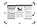
WARNING
EWA10061
Never turn the key to “OFF” or
“LOCK” while the vehicle is moving.
Otherwise the electrical systems will
be switched off, which may result in
loss of control or an accident.
EAU10683
LOCK
The steering is locked, and all electrical
systems are off. The key can be re-
moved.
To lock the steering
1. Turn the handlebars all the way to
the left.
2. Push the key in from the “OFF” po-
sition, and then turn it to “LOCK”
while still pushing it.
3. Remove the key.
ON
OFF
LOCK
1. Push.
2. Turn.
12
U2S312E0.book Page 1 Thursday, June 3, 2010 9:43 AM

INSTRUMENT AND CONTROL FUNCTIONS
4-2
4
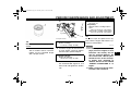
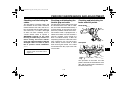
To unlock the steering
Push the key in, and then turn it to
“OFF” while still pushing it.
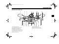
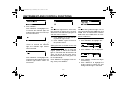
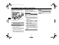
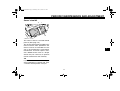
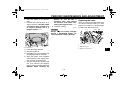
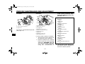
EAU49391
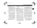
Indicator lights and warning
lights
EAU11030
Turn signal indicator lights “”
and “”
The corresponding indicator light flash-
es when the turn signal switch is
pushed to the left or right.
EAU11060
Neutral indicator light “”
This indicator light comes on when the
transmission is in the neutral position.
EAU11080
High beam indicator light “”
This indicator light comes on when the
high beam of the headlight is switched
on.
EAU46565
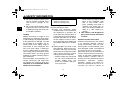
Oil level warning light “”
This warning light comes on if the en-
gine oil level is low.
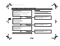
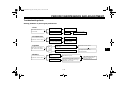
To check the electrical circuit of the
warning light, place the vehicle on a
level surface, set the engine stop
switch to “” and turn the key from
“OFF” to “ON”.
If the warning light does not come on
for a few seconds and then go off, have
a Yamaha dealer check the electrical
circuit.
If the warning light stays on, proceed as
follows.
1. Set the engine stop switch to “”.
2. Turn the key to “OFF”, wait two
minutes, and then turn the key to
“ON”.
1. Push.
2. Turn.
12
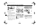
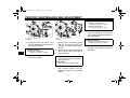
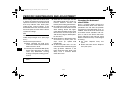
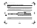
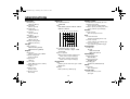
1. Shift timing indicator light
2. Fuel level warning light “”
3. Right turn signal indicator light “”
4. Coolant temperature warning light “”
5. Neutral indicator light “”
6. High beam indicator light “”
7. Engine trouble warning light “”
8. Left turn signal indicator light “”
9. Anti-lock Brake System (ABS) warning
light “”
10.Oil level warning light “”
10
9
2
1
3
4
5
8
7
6
ABS
U2S312E0.book Page 2 Thursday, June 3, 2010 9:43 AM

INSTRUMENT AND CONTROL FUNCTIONS
4-3
4
3. If the warning light comes on and
does not go off, check the engine
oil level. (See page 7-12.) If the
warning light still stays on after
confirming the oil level is correct,
have a Yamaha dealer check the
vehicle.
TIP
● This warning light will not come
on:
• when the engine is idling
• when riding
• if the engine has stalled and the
key has not been turned from
“ON” to “OFF” and then back to
“ON”
However, if the warning light is on
when the engine is started, it will
stay on until the key is turned to
“OFF”.
● This model is also equipped with a
self-diagnosis device for the oil
level detection circuit. If a problem
is detected in the oil level detection
circuit, the following cycle will be
repeated until the malfunction is
corrected: The oil level warning
light will flash ten times, then go off
for 2.5 seconds. If this occurs,
have a Yamaha dealer check the
vehicle.
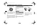
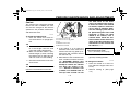
EAU48700
Fuel level warning light “”
This warning light comes on when the
fuel level drops below approximately
3.9 L (1.03 US gal, 0.86 Imp.gal). When
this occurs, refuel as soon as possible.
The electrical circuit of the warning light
can be checked by turning the key to
“ON”. The warning light should come
on for a few seconds, and then go off.
If the warning light does not come on
initially when the key is turned to “ON”,
or if the warning light remains on, have
a Yamaha dealer check the electrical
circuit.
TIP
This model is also equipped with a self-
diagnosis device for the fuel level de-
tection circuit. If a problem is detected
in the fuel level detection circuit, the fol-
lowing cycle will be repeated until the
malfunction is corrected: The fuel level
warning light, the fuel meter and the
fuel level warning indicator will flash
eight times, and then go off for 3.0 sec-
onds. If this occurs, have a Yamaha
dealer check the vehicle.
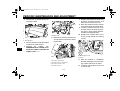
EAU11444
Coolant temperature warning
light “”
This warning light comes on if the en-
gine overheats. If this occurs, stop the
engine immediately and allow the en-
gine to cool.
The electrical circuit of the warning light
can be checked by turning the key to
“ON”. The warning light should come
on for a few seconds, and then go off.
If the warning light does not come on
initially when the key is turned to “ON”,
or if the warning light remains on, have
a Yamaha dealer check the electrical
circuit.
NOTICE
ECA10021
Do not continue to operate the en-
gine if it is overheating.
U2S312E0.book Page 3 Thursday, June 3, 2010 9:43 AM
Page is loading ...
Page is loading ...
Page is loading ...
Page is loading ...
Page is loading ...
Page is loading ...
Page is loading ...
Page is loading ...
Page is loading ...
Page is loading ...
Page is loading ...
Page is loading ...
Page is loading ...
Page is loading ...
Page is loading ...
Page is loading ...
Page is loading ...
Page is loading ...
Page is loading ...
Page is loading ...
Page is loading ...
Page is loading ...
Page is loading ...
Page is loading ...
Page is loading ...
Page is loading ...
Page is loading ...
Page is loading ...
Page is loading ...
Page is loading ...
Page is loading ...
Page is loading ...
Page is loading ...
Page is loading ...
Page is loading ...
Page is loading ...
Page is loading ...
Page is loading ...
Page is loading ...
Page is loading ...
Page is loading ...
Page is loading ...
Page is loading ...
Page is loading ...
Page is loading ...
Page is loading ...
Page is loading ...
Page is loading ...
Page is loading ...
Page is loading ...
Page is loading ...
Page is loading ...
Page is loading ...
Page is loading ...
Page is loading ...
Page is loading ...
Page is loading ...
Page is loading ...
Page is loading ...
Page is loading ...
Page is loading ...
Page is loading ...
Page is loading ...
Page is loading ...
Page is loading ...
Page is loading ...
Page is loading ...
Page is loading ...
Page is loading ...
Page is loading ...
Page is loading ...
Page is loading ...
Page is loading ...
Page is loading ...
Page is loading ...
Page is loading ...
Page is loading ...
Page is loading ...
Page is loading ...
Page is loading ...
Page is loading ...
Page is loading ...
Page is loading ...
Page is loading ...
Page is loading ...
Page is loading ...
Page is loading ...
Page is loading ...
Page is loading ...
Page is loading ...
Page is loading ...
Page is loading ...
Page is loading ...
Page is loading ...
Page is loading ...
Page is loading ...
Page is loading ...
Page is loading ...
-
 1
1
-
 2
2
-
 3
3
-
 4
4
-
 5
5
-
 6
6
-
 7
7
-
 8
8
-
 9
9
-
 10
10
-
 11
11
-
 12
12
-
 13
13
-
 14
14
-
 15
15
-
 16
16
-
 17
17
-
 18
18
-
 19
19
-
 20
20
-
 21
21
-
 22
22
-
 23
23
-
 24
24
-
 25
25
-
 26
26
-
 27
27
-
 28
28
-
 29
29
-
 30
30
-
 31
31
-
 32
32
-
 33
33
-
 34
34
-
 35
35
-
 36
36
-
 37
37
-
 38
38
-
 39
39
-
 40
40
-
 41
41
-
 42
42
-
 43
43
-
 44
44
-
 45
45
-
 46
46
-
 47
47
-
 48
48
-
 49
49
-
 50
50
-
 51
51
-
 52
52
-
 53
53
-
 54
54
-
 55
55
-
 56
56
-
 57
57
-
 58
58
-
 59
59
-
 60
60
-
 61
61
-
 62
62
-
 63
63
-
 64
64
-
 65
65
-
 66
66
-
 67
67
-
 68
68
-
 69
69
-
 70
70
-
 71
71
-
 72
72
-
 73
73
-
 74
74
-
 75
75
-
 76
76
-
 77
77
-
 78
78
-
 79
79
-
 80
80
-
 81
81
-
 82
82
-
 83
83
-
 84
84
-
 85
85
-
 86
86
-
 87
87
-
 88
88
-
 89
89
-
 90
90
-
 91
91
-
 92
92
-
 93
93
-
 94
94
-
 95
95
-
 96
96
-
 97
97
-
 98
98
-
 99
99
-
 100
100
-
 101
101
-
 102
102
-
 103
103
-
 104
104
-
 105
105
-
 106
106
-
 107
107
-
 108
108
-
 109
109
-
 110
110
-
 111
111
-
 112
112
-
 113
113
-
 114
114
-
 115
115
-
 116
116
-
 117
117
-
 118
118


Yamaha 2011 VMAX Owner's manual
- Category
- Motorcycles
- Type
- Owner's manual
Ask a question and I''ll find the answer in the document
Finding information in a document is now easier with AI
Related papers
-
Yamaha Motorcycle XV1700PCR User manual
-
-
-
-
-
-
-
-
-
Other documents
-
Honda CBF1000A Owner's manual
-
-
-
Coast HD7736CP Installation guide
-
-
-
Baotian BT49QT-11 User manual
-
-
 Fantic Motor Fantic 50 Enduro User manual
-
