Page is loading ...

pentair.com
INSTALLATION AND
OPERATION MANUAL
BELT-DRIVEN CENTRIFUGAL PUMP
9403C-1000-MTZ
L-1534 Rev. C (12-09-19)

Notes are used to notify of installation, operation, or main-
tenance information that is important but not safety related.
Caution is used to indicate the presence of a hazard, which
will or may cause minor injury or property damage if the
notice is ignored.
Warning denotes that a potential hazard exists and indi-
cates procedures that must be followed exactly to either
eliminate or reduce the hazard, and to avoid serious per-
sonal injury, or prevent future safety problems with the
product.
Danger is used to indicate the presence of a hazard that will
result in severe personal injury, death, or property damage
if the notice is ignored.
Do not pump flammable or explosive fluids such as gaso-
line, fuel oil, kerosene, etc. Do not use in explosive atmo-
spheres. Components not rated for use with Anhydrous
Ammonia. The pump should only be used with liquids
compatible with the pump materials. Failure to follow this
notice may result in severe personal injury and/or property
damage and will void the product warranty.
Be sure all exposed moving parts, such as PTO shafts and
adapters, are properly shielded or guarded and that all cou-
pling devices are securely attached before applying power.
The sound pressure level of the pump may exceed 80dBA.
Observe all safety precautions when operating the pump
within close proximity for extended periods by wearing hear-
ing protectors. Extended exposure to elevated sound levels
will result in permanent loss of hearing acuteness, tinnitus,
tiredness, stress, and other effects such as loss of balance
and awareness.
• DO NOT EXCEED maximum recommended speed and
pressure for pump and eqipment being used.
• Operate the pump between a temperature range of 45
o
to 140
o
F [7
o
to 60
o
C]. Protect pump from freezing con-
ditions by draining liquid and pumping rust-inhibiting
antifreeze olution through the system, coating the pump
interior.
• Make certain that the power source conforms to the
requirements of your equipment.
• Provide adequate protection in guarding around the
moving parts such as shafts and pulleys.
Pumps mounted directly onto PTO shaft or other power shaft
must be prevented from rotating with the power shaft. Pump
must float freely on the power shaft and must not be tied
rigidly to equipment on which it is mounted.
• Release all pressure within the system before servicing
any component.
Before servicing, disconnect all power. Make sure all pres-
sure in the system is relieved. Drain all liquids from the
system and flush.
• Drain all liquids from the system before servicing.
• Secure the discharge line before starting the pump. An
unsecured discharge line may whip, resulting in person-
al injury and/or property damage.
• Check all hoses for weak or worn condition before each
use. Make certain that all connections are tight and
secure.
• Periodically inspect the pump and the system compo-
nents. Perform routine maintenance as required (See
Maintenance).
• Use only pipe, hose, and hose fittings rated for max-
imum rated pressure of the pump or the pressure at
which the pressure relief valve is set at. Do not use used
pipe.
• Do not use these pumps for pumping water or other liq-
uids for human or animal consumption.
• Hypro pumps are not designed to be used as clean water
pumps as defined in 10CFR Parts 429 and 431.
Form L-1534 (Rev. C)
2
General Safety Information
California Proposition 65 Warning -- This product and related accessories contain chemicals known to the State of
California to cause cancer, birth defects or other reproductive harm.
Description
Hypro Centrifugal Pumps handle big, high-capacity farm
spraying jobs with ease. Use them for spraying liquid
fertilizers and other chemicals, including wettable powder
slurries for weed control. Make short work of other farm
jobs - filling nurse tanks, watering seed beds, and trans-
ferring liquids.
Available in a variety of models, Hypro centrifugal pumps
give you the choice of economical, simple belt drive, or
sturdy, smooth-running oil-bath gear-driven units. Many
models are also available in lightweight polypropylene
(pump portion only) for resistance to corrosive liquids
such as acid-based fertilizers.

Form L-1534 (Rev. C)
3
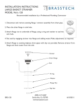
Anti-Rotation Kit No. 3430-0796
for 9403C-1000-MTZ belt drive
with 8-spline hollow shaft (1-3/8”)
The idler arm is greased at the factory. Re-grease after 250
hours of operation or at the start of each season. Also grease
whenever idler arm is removed from pump. To grease, use a
grease gun with the installed grease fitting located on the outer
edge of the idler arm.
The mechanical seal in the pump is lubricated by liquid being
pumped. Do not run the pump dry. Pump bearings are factory
lubricated and do not require further lubrication in the field.
Lubrication
Pump Assembly
PTO Shaft
Anti-Rotation Pin
Nut, M16x2
Washer
Hairpin Cotter Pin
Washer
Anti-Rotation Pin
Nut, M16x2
Hairpin Cotter Pin
Hazardous Substance Alert
1. Always drain and flush pump before servicing or disassem-
bling for any reason (see instructions).
2. Always drain and flush pump prior to returning unit for
repair.
3. Never store pumps containing hazardous chemicals.
4. Before returning pump for service/repair, drain out all liquids
and flush unit with neutralizing liquid. Then, drain the pump.
Attach tag or include written notice certifying that this has
been done.
It is illegal to ship or transport any hazardous chemicals
without United States Environmental Protection Agency
Licensing.
Drive Source Installation
Tractor PTO Installation
Series 9400 Belt-Drive Centrifugal Pumps
Series 9400 Pumps are designed for ease of installation and
removal with tractor-mounted sprayers. Refer to following sec-
tion for proper installation of the pump. Pump life is increased
by reducing both pump driver hub and PTO shaft wear due to
vibration.
To prevent pump from turning on PTO shaft, install an anti-rota-
tion pin as follows (see Anti-Rotation Kit No. 3430-0796):
1.
Remove any bolt that may be in the lower right hole of the
PTO unit mounting cover (looking from end of shaft).
2. Insert the threaded M16 anti-rotation pin (from Anti-Rotation
Kit No. 3430-0796 recommended) into the lower right hole
of the PTO unit mounting cover (looking from end of shaft)
and thread pin in until tightened against nut on pin.
3. Slide 8-spline PTO hub on pump over the PTO shaft on the
back of the tractor, making sure to line up the anti-rotation
pin to slide through the anti-rotation pin hole on the bearing
housing.
4. Slide washer (provided in Anti-Rotation Kit No. 3430-0796)
onto anti-rotation pin (also provided in kit).
5. Insert hairpin (provided in Anti-Rotation Kit No. 3430-0796)
through the hole at the end of the anti-rotation pin to prevent
pump from sliding off PTO shaft.
This manual will cover the installation of the basic belt-driven
Hypro Centrifugal Pump. Consult the manufacturer of your trac-
tor, motor or engine for additional information.
Read all instructions and general safety information before
attempting to install or operate the pump.

Form L-1534 (Rev. C)
4
Plumbing Installation
Centrifugal Plumbing Hook-up
REF. DESCRIPTION
NO.
1 Tank Lid
2 Vent Line #3430-0456
3 Jet Agitator
4 Shut-off Ball Valves
5 Centrifugal Pump
6 Spray Control Console
7 Centrifugal Pump Control
8 Manifold Boom Valve
9 Electromagnetic Flowmeter
10 Compact Jet Turret Nozzle Body
1
3
5
7
4
2
9
8
6
10

Form L-1534 (Rev. C)
5
Installation Instructions
Pump Installation:
The following are recommendations to achieve the opti-
mal performance out of your centrifugal pump and your
spraying system.
Pump Inlet Line
To achieve full capacity from the pump, the inlet line
should be at least the same size as the inlet port on the
pump. Reducing this line size will restrict the capabili-
ties of the pump. The line must also be free of air leaks.
Check all fittings and connections in the suction line for
tightness. The introduction of air may affect the priming
and pumping capabilities of the pump. Use good quality
suction hose that will not be collapsed by suction.
For non-self priming models, the centrifugal pump should
be mounted below the liquid level and as near to the
liquid source as possible to allow for the shortest suction
line practical. To achieve optimal performance, the suc-
tion line should slope down into the pump. Avoid rises
and humps that could trap air in the line to the pump.
The suction line and pump should be filled with liquid
prior to starting the pump, and all discharge lines should
be open.
Pump Outlet Line
The recommended orientation for the outlet port is point-
ing upwards. This allows liquid to stay in the pump while
it is priming. The outlet line should be the same size as
the pressure port on the pump to give the optimal flow.
The line should have as few restrictions and elbows as
possible to optimize the pump performance and reduce
pressure drop from the pump to the spray tips.
Priming the Pump:
NOTE:
THE PUMP MUST NOT BE RUN DRY.
In addition to the proper suction plumbing, a vent line
should be installed to assist in priming. Use Hypro Vent
Line Kit 3430-0456. The vent line will help prevent air
locks and allows air to bleed off to the tank. This helps
ensure proper priming and helps to prevent dry-run
damage to the mechanical seal during priming. The vent
line should be installed in the top port of the pump cas-
ing and the line routed sloping upward to the tank, where
it should be mounted above the liquid line.
Before starting the pump, the inlet line and pump must
be filled with liquid and all discharge lines must be open.
On self-priming models, only the pump chamber needs
to be filled with liquid. The pump must not be run unless
it is completely filled with liquid because there is a dan-
ger of damaging the mechanical seal, which depends on
the liquid for its lubrication.
Non-self-priming models should be mounted below the
level of the liquid. The suction line should slope down to
the pump and be free of dips and bends. If this cannot
be done, a foot valve should be installed in the end of
the inlet line so that the line can be completely filled with
liquid before starting the pump.
Centrifugal Pump Control
Hypro now offers many different components for spray-
ing systems. The Hypro centrifugal pump control incor-
porates the electric flow control valve, a self-cleaning line
strainer, a visual pressure gauge and a manual agitation
control valve.
Flow Control Valve
A high-flow electric proportional valve allows for maxi-
mum flow control to the boom valves. It provides smooth,
rapid control that can be controlled from either an elec-
tronic rate controller or switch box.
Strainers
The recommended placement of the strainer for a cen-
trifugal pump is in the pump outlet line. This will eliminate
any possible restriction that the strainer could create if
it were installed in the inlet line. Ensure that the proper
strainer size and screen mesh are used to limit the pres-
sure drop and achieve the best filtration. Line strainers
can also be installed in the tank fill line to filter liquid as
it is loaded into the tank as well as in the boom lines to
further filter the solution prior to the spray tips. Tank bas-
kets can also be used to filter material added through the
tank lid.
Agitation
The centrifugal pump control contains a manual agitation
control valve that can be adjusted to provide the right
amount of flow to the jet agitators in the tank to ensure
proper mixing within the tank.
Flowmeter
To eliminate the mechanical problems of a turbine flow-
meter, we recommend that an electromagnetic flowmeter
be used. These flowmeters have no moving parts to
wear out and will provide a more consistent
and accurate flow reading. They can be input into just
about any electronic rate controller or switch box.
Boom Section Valves
For rapid response and reliability, we recommend elec-
tric plunger valves be used for boom control. The valves
should be sized accordingly to minimize the pressure
drop and maximize the flow rate. The boom tubing or
hose should be sized accordingly to ensure that a pres-
sure drop in the lines does not occur, causing inconsis-
tent pressures at the nozzles.
Nozzle Bodies
Nozzle bodies with shut-off check valves are recom-
mended to eliminate dripping from the spray tips when
the boom valves are shut down.
For further information
regarding Hypro products,
contact your local dealer
or Hypro directly at www.
hypropumps.com or by call-
ing +1 651 766 6300.

Form L-1534 (Rev. C)
6
Operation and Maintenance
Engage the PTO clutch slowly and smoothly. Avoid
sudden starts and fast clutching that may damage the
drive section of the pump.
Controlling the Flow
Two Flow Control Valves are used - one in the agitation
line and one in the line leading to the boom or spray gun.
This permits controlling agitation flow independently of
nozzle flow.
To Adjust For Spraying
To adjust the sprayer (regardless of power source), follow
these steps:
1. Prime the pump with all valves open.
2. Close control valve and agitation line valve; then open
the boom shut-off valve.
3. With the pump running, open the control valve until the
pressure gauge indicates desired spraying pressure.
4. Open the the agitation line valve until sufficient agi-
tation is observed. Then, if spraying pressure drops,
readjust the control valve to restore desired pressure.
5. Make sure flow is uniform from all nozzles.
After spraying adjustments are made, it is only necessary
to close the boom shut-off valve to discontinue spraying.
On belt drive models, check belt tension daily or before
each use.
Flush Pump After Use
One of the most common causes for faulty pump per-
formance is “gumming” or corrosion inside the pump.
Flush the pump and entire system with a solution that will
chemically neutralize the liquid pumped. Mix according to
manufacturer’s directions. This will dissolve most residue
remaining in the pump, leaving the inside of the pump
clean for the next use.
To Prevent Corrosion
After cleaning the pump as directed above, flush it with a
permanent-type automobile antifreeze (Prestone, Zerex,
etc.) containing a rust inhibitor. Use a 50/50 solution of
antifreeze and water. Plug the ports to keep out air during
storage. For short periods of idleness, non-corrosive
liquids may be left in the pump, but air must be kept out.
Plug the ports or seal port connections.

Always flush the pump with water or neutralizing
agent before servicing.
Pump Housing Disassembly
In most cases, seal replacement requires
disassembly of only the pump half of the unit.
1. Remove the safety shield cover. Insert a 15/16”
socket onto idler arm bolt head and apply tension
in a counterclockwise direction. Slip thebelt off of
the large pulley. Remove the belt. Remove the
retaining ring securing the driver pulley onto the
shaft; then slide the driver pulley and key off the
8-spline shaft. Remove the set screw securing the
driven pulley to the pump shaft; then slide the driven
pulley and key off the pump shaft. Remove the
retaining ring securing the idler bracket assembly to
the mounting flange (See Figure 6). Slide the idler
bracket assembly and torsion spring off the mounting
flange (See Figure 6). Remove the safety shield from
the assembly by unscrewing the three 1/4-20 screws
securing it. Remove the bearing housing bracket
from pump (See Figure 2).
2. Remove the four casing cap screws with a 9/16” box
end wrench. Tap the pump casing discharge port
with rubber hammer, if necessary, to break it loose
from the mounting flange. Check inside of pump
casing including the suction port. If it is badly eroded
or damaged, the pump casing should be replaced.
Remove and discard the o-ring. The o-ring should
always be replaced.
3. To remove the impeller nut, clamp the flange in a
vise and insert a large screwdriver or file (at least 10”
long) into the impeller vanes to prevent the impeller
from turning when loosening the impeller nut. Use a
socket wrench to remove the impeller nut by turning
it counterclockwise (See Figure 3).
4. Once the nut is removed, place a screwdriver on
each side (See Figure 4) behind the impeller and pry
away from the mounting flange. Remove o-ring from
the mounting flange.
Form L-1534 (Rev. C)
7
Repair Instructions
Figure 2
Removing the Bearing Housing
Figure 4
Removing the Impeller
Figure 3
Removing the Impeller Nut
Figure 1
Recommended Repair Tools
3010-0020
3010-0061
3010-0064
3010-0084
3010-0065
3010-0167
3010-0067
3020-0009
3010-0066

Pump Shaft and Bearing Assembly Removal
and Replacement
The pump must be separated from the belt drive prior
to removal of the pump shaft and bearing.
1. Remove the set screws securing the driven pulley to
the pump shaft; then slide the driven pulley and key off
the pump shaft (See Figure 6).
Special attention should be exercised when working
with retaining rings. Always wear safety goggles when
working with spring or tension-loaded fasteners or
devices.
2. Remove the retaining ring securing the idler bracket
assembly to the mounting flange (See Figure 6).
3. Slide the idler bracket assembly and torsion spring off
the mounting flange (See Figure 6).
1. Remove the internal retaining ring from the mounting
flange.
2. Place the mounting flange on an arbor press with the
shaft end facing up: then press the shaft and both
bearings out of the mounting flange (See Figure 7).
3. Using an arbor press, press the old bearings off the
shaft (See Fig. 8). Because the center portion of the
shaft has a thicker diameter than the ends, the bear-
ings must be pressed off each end of the shaft.
Figure 6
Driven Pulley
Retaining Ring
Idler Bracket Assembly
Torsion Spring
Mounting Flange
Pump Seal Removal
1. Apply lubricant (WD-40 oil, LPS or detergent) to shaft
and rubber boot area of rotary seal for easier removal.
Push seal down to allow lubricant to penetrate around
shaft.
2. To remove (Rotary Part) of seal, use two screw
drivers positioned on each side and pry up the rotary
part of the seal (Fig. 5.)
3. Remove (Stationary Part) of seal from mounting
plate. Knock seal out from back with a hammer and
screw driver. It may be necessary to destroy the sta
tionary seal seat with a punch or chisel for removal.
Silicon carbide material is very brittle and will crack
easily.
The seal will be damaged from removal. A new seal
MUST be used when pump is reassembled.
In the case of a severe pump seal leak, inspect the shaft
for possible contamination.
Form L-1534 (Rev. C)
8
Figure 7
Pressing Shaft and Bearings out of Mounting Flange
Figure 5
Removing the Pump Seal
Clean-Up Of Pump Housing
1. Using a circular bottle-type wire brush with air or hand
drill, clean the outlet port, inlet port and the sealing areas
of the o-ring on the pump casing and mounting flange.
Using the port brush, clean the seal cavity in the mounting
flange.
2. After wire brush cleaning, it is recommended that the
pump casing and mounting flange be further cleaned in a
solvent tank to remove rust and corrosion particles.

Seal Replacement/Pump Housing
Reassembly
Be extremely careful with the new seal. Silicon carbide
material is very hard, but also very brittle. If the seal is
accidentally dropped and hits a hard surface, the seal’s
primary ring (rotary part) and mating ring (stationary
seal seat) can be damaged. Also take precautions not to
introduce dirt or grit to the seal surfaces.
Mating Ring Primary Ring Head Assy.
(Stationary Part) (Rotary Part)
1. Inspect seal seat cavity to be sure it is clean and
without debris. Foreign material at the bottom of the
seal seat bore can cause the mating ring to be
slightly cocked.
Important: Make sure seal cavity is clean and lubricated
with detergent; don’t use oil for assembly lubrication.
2. Lubricate outside diameter of (Stationary Part) of the
mechanical seal and seal seat cavity in mounting
flange with detergent (i.e. soap and water) to aid in
smooth installation. (See Fig. 10.)
3. Press (Stationary Part) of seal into seal cavity bore
on pump mounting plate using a rag over the seal
face and a 1-3/8” plastic guide, applying uniform
force (See Figure 11). Be sure seal is completely
seated to the bottom and not cocked.
Important: Do not rotate or thread (Rotary Part) of seal
down on shaft over threaded area. This may cause cuts
or damage to inside of (Rotary Part) rubber boot.
4. Insert the key into shaft key slot. Place the Impeller
on the shaft. Put the impeller nut on the shaft, and
using a large screwdriver or file inserted into the
impeller vanes for support, tighten impeller nut
securely.
5. Lubricate the o-ring with soap and water, then install
o-ring on pump mounting plate. Replace o-ring if
worn or damaged.
6. Reassemble pump casing with four hex bolts and
medium strength thread locker (torque to 25 ft-lbs.)
using a 5/8” box wrench, and tighten bolts evenly to
compress o-ring seal.
Form L-1534 (Rev. C)
9
Figure 8
Pressing Bearings off Shaft
4. Support the inner races of the new bearings; then
press the shaft into the new bearings.
5. Pressing on the outer race of the new bearings, press
the new bearings into the mounting flange.
6. Install the internal retaining ring.
Fig. 9
Fig. 10
Fig. 11

Form L-1534 (Rev. C)
10
Belt Replacement
1. Remove the safety shield.
2. Insert a 15/16” socket onto idler arm bolt head and
apply tension in a counterclockwise direction.
3. Slip the belt off of the large pulley.
4. Wrap the new belt around the small pulley and on the
inside of the idler pulley.
5. Insert a 15/16” socket onto idler arm bolt head and
apply tension in a counterclockwise direction.
6. Slip the belt around the large pulley, ensuring that the
grooves on the pulleys match the grooves on the belt.
Belt Alignment and Tension
PERIODICALLY CHECK BELT FOR
WEAR AND ALIGNMENT.
1. Remove the safety shield. Inspect the belt for wear
and alignment. Proper alignment will reduce belt and
pulley wear.
2. Refer to Figure 13 to align the belt. Place a straight
edge on the outer edge of the large pulley. Measure
the distance from the straight edge to the edge of the
belt (Point A). This should be the same as the dis-
tance between the straight edge and the belt at the
small pulley (Point B). Loosen the set screws on the
small pulley, and adjust the pulley until both distances
are equal. Tighten the set screws.
3. To ensure proper tension, check for free rotation of
the tension arm. Grease the provided fitting regularly.
If properly lubricated, the tension arm will automatical-
ly keep proper tension.
Idler Bearing Replacement
1. Remove the belt.
2. Remove the idler bolt with a 15/16” impact socket.
3. Remove the idler pulley snap ring.
4. Press out the bearing using an arbor press.
5. To reassemble, reverse the procedure.
Pedestal Bearing Replacement
1. Remove the belt.
2. Remove the large pulley retainer ring and pulley.
(For quick coupled models, remove the outer keeper
ring and keeper balls.)
3. Remove the bearing retainer ring.
4. Using an arbor press, press out the driver hub and
bearing assembly from the pedestal bearing bore.
5. Remove first bearing from shaft using an arbor press.
6. Remove both snap rings from shaft, then press sec-
ond bearing off shaft using an arbor press.
7. Install new bearings and reverse the procedure for
reassembly.
Troubleshooting
Symptom Probable Cause(s) Corrective Action(s)
Low Discharge Pump not primed. Remove topmost vent plug from face of pump and
run pump to expel trapped air (See Installation Instructions).
Air leaks in suction line. Check and reseal inlet fittings.
Blocked or clogged line strainer. Inspect strainer and clear any debris from screen.
Impeller plugged. Inspect and clear obstruction.
Undersize suction line or collapsed hose. Suction line should be the same diameter as inlet port of pump or
larger.
Eye of impeller rubbing on volute. Remove volute (front cover) and inspect the impeller. If wear
detected, sand the impeller eye O.D. with emery cloth.
B
Straight
Edge
A
Figure 13
Figure 12
Mechanical Seal Installation

Form L-1534 (Rev. C)
11
Performance Data
Metric Units
L/min
GPM
P
S
I
B
A
R
U.S. Units

Form L-1534 (Rev. C)
12
Model 9403C-1000-MTZ
7
9
10
11
12
16
17
18
19
20
21
22
23
24
25
26
27
28
29
30
31
34
35
38
39
40
42
41
43
44
45
46
37
36
33
32
13
14
15
8
1
3
2
5
4
6
47

Form L-1534 (Rev. C)
13
26 1 3115-0036 Idler Pulley
27 1 2000-0010 Ball Bearing
28 1 1820-0013 Retainer Ring
29 1 2210-0111 Hex Head Cap Screw
30 1 1800-0014 Retaining Ring
31 2 2007-0063 Bearing
32 2 1810-0001 Retaining Ring
33 1 0504-9400M Shaft - 8 spline, broached
34 1 22791-SHW Key
35 2 1600-0070 Spring Pin
36 1 0708-9400D Bearing Housing
37 1 2028-0008 Bearing, Bushing
38 4 2250-0110 Bolt, M5 x 0.8 w/nylon insert
39 1 2840-0096 Shroud
40 3 2270-0139 Washer, Flat, 1/4”
41 3 2210-0002 Screw, 1/4-20 UNC
42 1 3115-0040 Pulley
43 1 1810-0031 Retaining Ring
44 1 3100-0005 V-Belt
45 1 2840-0097 Shroud Cover
46 4 2270-0138 Washer, Flat, M5
47 4 25163 M5 Hex Head Cap Screw
Ref. Qty.
No. Req’d. Part No. Description
1 1 0150-9000C2 Housing, 1-1/2” x 1-1/4” NPT CI
2 1 2253-0002 Acorn Nut
3 1 0401-9100P Impeller, Nylaglass KB
4 1 1720-0083 O-ring
5 1 2120-0039 Mechanical Seal (Viton, 5/8”)
6 1 0750-9200C6 Mounting Flange
7 1 2270-0076 Tag
8 1 2270-0041 Washer
9 1 6031-0325 Decal
10 4 2210-0020 Screw, Hex Head Cap
11 1 1410-0056 Slinger Gasket, Shaft
12 2 2210-0055 Screw, Hex Head Cap
13 2 2260-0006 Lockwasher
14 2 2000-0008 Ball Bearing
15 1 1610-0015 Key
16 1 0509-9200 Shaft, Pedestal
17 1 1610-0004 Key
18 1 1820-0012 Snap Ring
19 1 3115-0041 Pulley
20 2 2230-0003 Socket Set Screw
21 1 1900-0156 Spring
22 1 0706-9403C Idler Arm
23 1 2405-0003 Grease Fitting
24 1 1810-0036 Retaining Ring
25 1 1410-0095 Idler Spacer
Ref. Qty.
No. Req’d. Part No. Description
NOTE: When ordering parts, give
QUANTITY, PART NUMBER,
DESCRIPTION, and COMPLETE
MODEL NUMBER. Reference
numbers are used ONLY to
identify parts in the drawing and
are NOT to be used as order
numbers.
Model 9403C-1000-MTZ
Life Guard Seal Kit No. 3430-0589
consists of (1) Ref. 4 O-ring and (1)
Ref. 5 Mechanical Seal

Form L-1534 (Rev. C)
Notes
14

Form L-1534 (Rev. C)
Notes
15

For a detailed list of where Pentair trademarks are registered, please visit www.pentair.com/en/registrations.html. Pentair trademarks and logos are owned by Pentair PLC. or its aliates.
Third party registered and unregistered trademarks and logos are the property of their respective owners. Because we are continuously improving our products and services, Pentair
reserves the right to change specications without prior notice. Pentair is an equal opportunity employer.
L-1534 Rev. C (12-09-19) ©2019 Pentair. All Rights Reserved.
Hypro/Shurflo (hereafter, “Hypro”) agricultural products are warranted to be free of defects in material and workmanship under normal use
for the time periods listed below, with proof of purchase.
- Pumps: one (1) year from the date of manufacture, or one (1) year of use. This limited warranty will not
exceed two (2) years, in any event.
- Accessories: ninety (90) days of use.
This limited warranty will not apply to products that were improperly installed, misapplied, damaged, altered, or incompatible with fluids or
components not manufactured by Hypro. All warranty considerations are governed by Hypro’s written return policy.
Hypro’s obligation under this limited warranty policy is limited to the repair or replacement of the product. All returns will be tested per
Hypro’s factory criteria. Products found not defective (under the terms of this limited warranty) are subject to charges paid by the returnee
for the testing and packaging of “tested good” non-warranty returns.
No credit or labor allowances will be given for products returned as defective. Warranty replacement will be shipped on a freight allowed
basis. Hypro reserves the right to choose the method of transportation.
This limited warranty is in lieu of all other warranties, expressed or implied, and no other person is authorized to give any other warranty or
assume obligation or liability on Hypro’s behalf. Hypro shall not be liable for any labor, damage or other expense, nor shall Hypro be liable for
any indirect, incidental or consequential damages of any kind incurred by the reason of the use or sale of any defective product.
RETURN PROCEDURES
All products must be flushed of any chemical (ref. OSHA section 1910.1200 (d) (e) (f) (g) (h)) and hazardous chemicals must be labeled/tagged
before being shipped
†
to Hypro for service or warranty consideration. Hypro reserves the right to request a Material Safety Data Sheet from
the returnee for any pump/product it deems necessary. Hypro reserves the right to “disposition as scrap” products returned which contain
unknown fluids. Hypro reserves the right to charge the returnee for any and all costs incurred for chemical testing, and proper disposal
of components containing unknown fluids. Hypro requests this in order to protect the environment and personnel from the hazards of
handling unknown fluids.
Be prepared to give Hypro full details of the problem, including the model number, date of purchase, and from whom you purchased your
product. Hypro may request additional information, and may require a sketch to illustrate the problem.
Contact the appropriate Hypro Service Department to receive a Return Merchandise Authorization number (RMA#).
Returns are to be shipped with the RMA number clearly marked on the outside of the package. Hypro shall not be liable for freight damage
incurred during shipping. Please package all returns carefully. All products returned for warranty work should be sent shipping charges
prepaid:
LIMITED WARRANTY ON HYPRO/SHURFLO AGRICULTURAL PUMPS & ACCESSORIES
AMERICAS & ALL OTHER REGIONS
Hypro / Pentair
Attention: Service Department
375 Fifth Avenue NW
New Brighton, MN 55112
Service: 800-468-3428
Fax: 651-766-6618
Technical: 800-445-8360
hypro.technicalpentair.com
CANADA
Pentair Water Belgium B.V.B.A
Industriepark Wolfstee
Toekomstlaan 30, 2200
Herentals, Belgium
Tel: +32 14 259 911
Fax: +32 14 259 975
shuro.service@pentair.com
CENTRAL & SOUTH AMERICA
+55 (11) 3317-5085
vendas.pwdb@pentair.com
pentair.com
†
Carriers, including U.S.P.S., airlines, UPS, ground freight, etc., require specific identification of any hazardous material being shipped. Failure to do so may result in a substantial fine and/or prison term.
Check with your shipping company for specific instructions.
/