Page is loading ...

GPC X1-LD liftgate,
GPC X1-LDF liftgate
User Manual
LIFT CORP.
11921 Slauson Avenue
Santa Fe Springs, CA 90670-2221
P 800.227.4116 / 562.464.0099
F 888.771.7713
Date 08.2020
Part No. 20 912 419

Contact information
Contact information
MAXON LIFT CORP.
Corporate Office
11921 Slauson Avenue
Santa Fe Springs, CA 90670-2221
P 800.227.4116 / 562.464.0099
F 888.771.7713
Customer Service / Parts
USA/Canada
Mexico
P 800.227.4116
F 888.771.7713
P 01.664.231.6039

Contents
III
Contents
Contact information ................................................................................................. II
Contents ................................................................................................................... III
General ............................................................................................................... 1
1.1 Purpose of the user manual ......................................................................... 1
1.2 Accompanying documents ........................................................................... 1
1.3 Description of the MAXON liftgate ............................................................... 1
1.4 Overview of the MAXON GPC X1-LDF liftgate ............................................ 2
1.5 Overview of the MAXON GPC X1-LD liftgate .............................................. 3
1.6 Description of the MAXON liftgate components ........................................... 4
1.7 Information, spare parts ordering, and warranty services
using the liftgate serial number and rating plate .......................................... 5
1.8 The liftgate serial number and the rating plate ............................................. 5
Safety .................................................................................................................. 6
2.1 Presentation of warning notices ................................................................... 6
2.2 Safety .......................................................................................................... 6
2.3 Fundamental hazards (hazards caused by the liftgate) ............................... 7
2.4 Emergency procedure ................................................................................. 8
2.5 Safety devices on the liftgate ....................................................................... 8
2.6 Intended use ................................................................................................ 8
2.7 Responsibilities of operating company and requirements for operator ........ 9
2.8 Commissioning .......................................................................................... 10
2.9 Handling and behavior during operation .................................................... 13
2.10 Danger notice sticker “Safe handling of the liftgate” .................................. 16
2.11 Permissible loads ....................................................................................... 17
2.12 Load diagram ............................................................................................. 18
Operation of the GPC X1-LD and GPC X1-LDF liftgates ............................... 19
3.1 Activating the liftgate .................................................................................. 19
3.2 Operation using the control panel (membrane switch) ............................... 19
3.3 Operation using the optional foot controls ................................................. 20
3.4 Operation using the optional handheld control with spiral cable ................ 21
3.4.1 Operating positions and safety distances
when using the optional handheld control with spiral cable .............. 22
3.5 Using the bridge plates .............................................................................. 23
3.6 Detailed operating sequence for the GPC X1-LDF .................................... 24
Maintenance ..................................................................................................... 28
4.1 Daily visual inspections .............................................................................. 28
4.2 Annual inspection ...................................................................................... 28
4.3 Care, maintenance, testing, and repair ...................................................... 28
Fault diagnosis and fault elimination ............................................................. 32
5.1 Explanation of diagnostic LED in the control unit ....................................... 32
5.2 Checking the tilt sensor in the platform ...................................................... 32
5.3 Checking pressure switch S4 ..................................................................... 32

Contents
IV
5.4 Support for fault diagnostics and elimination ............................................. 33
5.5 When electric motor is operated continuously
“liftgate cannot be switched off” ................................................................. 35
5.6 Emergency! Platform moved by mechanical means .................................. 36
5.7 Malfunction ................................................................................................ 36
Decommissioning, disassembly, and disposal ............................................. 37
Electrical circuit diagram ................................................................................ 40
Hydraulic circuit diagram ................................................................................ 41
Warranty, liability exclusions, copyright ....................................................... 42
9.1 Warranty .................................................................................................... 42
9.2 Purchase Part Warranty............................................................................. 42
9.3 Liability exclusions ..................................................................................... 43
9.4 Copyright ................................................................................................... 43
Notes ................................................................................................................. 44

General
1
General
1.1 Purpose of the user manual
This user manual is intended for owners and operators of the liftgate. Read this user
manual carefully before operating the MAXON liftgate. The manual will help familiarize
you with the liftgate’s mode of operation and warn you against misuse. The purpose of
the instructions it contains is to increase safety and improve product maintenance. These
instructions cover commissioning, operation, cleaning, maintenance, repair,
decommissioning, disassembly, and disposal.
Read this manual before working on or operating the liftgate.
Do not deviate from the instructions contained in this manual. By doing so, you risk
injury, damage to property, and voiding of the warranty.
Make sure that this manual always remains with the liftgate or vehicle.
IMPORTANT
This user manual must be kept in the driver’s cab as reference.
1.2 Accompanying documents
User manual Part No. 20 912 419
Electrical circuit diagram Part No. 20 910 824
Hydraulic circuit diagram Part No. 20 908 421
1.3 Description of the MAXON liftgate
You have chosen a liftgate of the highest quality. MAXON liftgates comply with the EU
Machinery Directive 2008/42/EG as well as DIN EN 1756–1. The MAXON liftgate is
simple to use. It is equipped with maintenance-free bearings and requires no lubrication
throughout its service life.

General
2
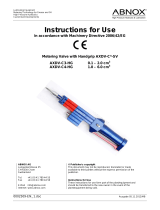
1.4 Overview of the MAXON GPC X1-LDF liftgate
The illustration shows the liftgate in the driving position
Lifting gear, compact power pack
GPC X1-LDF platform flipped open
1 Platform
2 Warning flags
3 License plate light
4 License plate holder
5 Lifting cylinder
6 Support arm
7 Step
8 Lifting arm
9 Closing arm
10 Compact power unit
11 Closing cylinder
12 Axle assembly
13 Warning lights
14 Mounting bracket (variant)
15 Control unit
16 Control panel
17 Bridge plates
18 Cart stop
3
4
8
9
7
1
6
2
5
10
11
12
13
14
15
17
16
18

General
3
1.5 Overview of the MAXON GPC X1-LD liftgate
The illustration shows the liftgate in the driving position
Lifting gear, compact power pack, platform
Bridge plate
1 Platform
2 Warning flags
3 License plate light
4 License plate holder
5 Lifting cylinder
6 Lifting arm
7 Closing arm
8 Foot control
9 Compact power unit
10 Closing cylinder
11 Axle assembly
12 Warning lights
13 Mounting bracket (variant)
14 Control unit
15 Control panel
16 Bridge plates
17 Cart stop
3
4
7
6
1
2
5
9
13
10
8
17
12
15
14
16
11
12

General
4
1.6 Description of the MAXON liftgate components
Electrical system/operating unit
The individual functions are controlled via a very flat control panel with four membrane
switches (see page 19). The interface between the liftgate and the vehicle complies with
ETMA guidelines.
Foot controls
The foot controls on the platform are mounted inside a protective, die-cast aluminum
housing. They can be used to lower the liftgate to the ground and lift it to the height of the
vehicle floor. The platform automatically tilts up and down to a position horizontal with the
ground.
Priority control
The foot controls are a priority control. When the liftgate is operated via the foot controls,
other control options (control panel, handheld control) are automatically locked out
electrically.
Hydraulics
The liftgate is driven by a compact power pack mounted on the supporting structure
(directly on the closing cylinder). It serves to move the lifting or closing cylinder to the
desired position. The hydraulic cylinder’s connecting rods are nitrided.
Lifting gear
The lifting gear (flange brackets as well as lifting and closing arms) comes with its final
surface ex works and is painted black (RAL 9005). All bearing points are maintenance-
free and require no lubrication. The flange brackets and installation adapters are adapted
to the frame of the vehicle type ex works. The interface complies with the ETMA
standard. Each liftgate type is tested with 80,000 load changes before being approved for
production.
Platform
The platform comprises clipped-together aluminum hollow sections that are stabilized by
means of welded tip and end sections. The platform has a smooth back for optimally
accommodating advertising labels.

General
5
1.7 Information, spare parts ordering, and warranty services using
the liftgate serial number and rating plate
You can order spare parts, submit warranty claims, and find technical information online
at https://www.maxonlift.com/support or you can send an e-mail to:
techservice@maxonlift.com, or contact our service personnel by calling
800-227-4116. You will need to give the liftgate serial number (see page 5).
You’ll find the electrical circuit diagram on page 40 and the hydraulic circuit diagram on
page 41.
1.8 The liftgate serial number and the rating plate
The liftgate serial number is the liftgate’s most important ID number. It is required for all
technical support, spare parts orders, and warranty claims and is found on every device
on a rating plate located in three positions:
Position 1
The rating plate with the loading diagram and serial number is affixed to the closing arm
on the right side of the vehicle as viewed in the forward direction of travel.
Position 2
The same rating plate is also affixed to the inside of the power pack cover.
Position 3
The serial number is also stamped into the mounting flange on the left as viewed in the
forward direction of travel.
Stamped serial number
Serial no. on the closing arm
F
a
b
r
i
k
N
u
m
m
e
r
Inside the power pack cover

Safety
6
Safety
2.1 Presentation of warning notices
The following types of notices are used in this manual to identify hazards and
complications:
DANGER
Failure to heed this notice can result in death or serious injury.
WARNING
Failure to heed this notice can result in death or serious injury.
CAUTION
Failure to heed this notice can result in minor or moderate injury.
NOTICE
Failure to heed this notice can result in damage to property or the
environment.
And:
IMPORTANT
Important information or useful tip for correct use.
2.2 Safety
The “Safety” section describes the safe operation of the MAXON liftgate. Correct
operation of the liftgate will guard against misuse and prevent injury and damage to
property.
WARNING
Do not deviate from the instructions contained in this manual for safely operating
the liftgate. By doing so, you risk injury, damage to property, and voiding of the
warranty.

Safety
7
2.3 Fundamental hazards (hazards caused by the liftgate)
DANGER
Electrical system with on-board voltage:
The liftgate receives electrical power from the vehicle’s on-board power supply
(max. 48 V DC). The electrical system is designed using state-of-the-art technology.
Do not damage or modify electrical components or wiring.
Fire and explosion hazard. Excessive current may damage the battery or cable harness.
To prevent this, visually inspect the electrical system (maintenance schedule).
DANGER
High-pressure hydraulic system:
The liftgate’s hydraulic system operates at high pressure (max. 220 bar). The hydraulic
system is designed using state-of-the-art technology.
Do not damage or modify hydraulic components or hoses.
Danger from pressurized liquids and gases.
Hydraulic components/lines can burst and cause injury.
Inspect hydraulic components/lines at regular intervals (maintenance schedule).
Install only state-of-the-art hydraulic components/lines.
DANGER
Moving parts with crushing points:
All parts that move in close proximity to one another can potentially crush fingers.
Watch out for the unexpected movement of moving parts.
DANGER
Moving parts with points where objects can be pulled in and/or trapped:
Parts of the body, long hair, and clothing are at risk of being caught and pulled in by
moving parts. This can result in fatal injuries.
Always secure long hair
Do not wear loose-fitting clothing
WARNING
Hinges with crushing points (on liftgate with platform foldover section):
Fingers are at risk of being crushed in the hinge area when the platform is folded and
unfolded.
Be careful when folding and unfolding the platform.

Safety
8
2.4 Emergency procedure
If you or another person working on or operating the liftgate experience a dangerous
situation: Immediately stop what you’re doing and seek expert help.
2.5 Safety devices on the liftgate
Hose rupture valves
If a hose, pipe, or screw connection bursts, the liftgate lowers or tilts in a controlled
manner at the permitted speed for as long as a function is being performed via one of the
control units (control panel, handheld control, manual control box, or foot controls). Once
the control unit is no longer being activated, the liftgate stops immediately.
Safety valve
The factory-set safety valve protects the liftgate against lifting loads that are heavier than
the specified load-carrying capacity. This valve may be adjusted only by a qualified
specialist using a test weight and a manometer.
Fuses
Defective fuses may only be replaced by fuses that correspond to the values specified in
the circuit diagram and on the control unit. Larger fuses may not be triggered by
malfunctions, which could result in cables catching fire.
2.6 Intended use
The MAXON liftgate was specially developed for cargo vans. The liftgate is used for
loading and unloading the vehicle and for transferring loads. Do not use the liftgate to lift
any person other than the operator. Any other use is prohibited.
WARNING
Incorrect or improper use or handling of the liftgate or, for example, errors caused by its
being operated by unqualified personnel can create risks for operators and bystanders
that may result in serious or fatal injuries.
IMPORTANT
To ensure safe operation of the liftgate, read the safety instructions and
warnings in the user manual provided.

Safety
9
2.7 Responsibilities of operating company and requirements for
operator
The operating company must comply with occupational safety regulations. The operating
company is responsible for providing personal protective equipment such as protective
footwear and protective clothing for operators and maintenance personnel. Valid accident
prevention regulations, legal and operational guidelines, occupational safety regulations,
and environmental regulations must be observed.
The operating company is responsible for annual inspections and the technologically
fault-free condition of the liftgate. An annual inspection must be carried out by qualified
personnel and the results of this inspection must be entered in the inspection record
book.
Any defects must be corrected and missing parts replaced immediately.
The operating company is responsible for the prompt repair of known defects.
IMPORTANT
Additional regulations are printed in the inspection record book. The inspection record
book is part of this user manual.
IMPORTANT
The inspection report dealing with the static and dynamic inspection performed before
commissioning the liftgate is kept in the inspection record book.
The liftgate must be operated in accordance with the user manual. The liftgate may be
operated, maintained, and serviced only by personnel who have received appropriate
training and have been specifically instructed in the dangers associated with its
operation.
Only persons aged 18 years or older who have been instructed in the operation and
maintenance of the liftgate and have proven their capability to the company are allowed
to independently operate and maintain the liftgate. They must be expressly assigned to
its operation and maintenance. The assignment for operating and maintaining the liftgate
must be issued in writing.
If more than one person is working on the liftgate, the operating company must appoint a
supervisor.
Liftgate maintenance may be performed by specially trained personnel only.
WARNING
Incorrect or improper use or handling of the liftgate or, for example, errors caused by its
being operated by unqualified personnel can create risks for operators and bystanders
that may result in serious or fatal injuries.
The liftgate may be operated only by qualified personnel.

Safety
10
2.8 Commissioning
(1) Do not use the liftgate before it is properly installed.
(2) Never operate the liftgate with the vehicle in motion.
(3) Operate the liftgate at your own risk.
(4) When operating the liftgate, secure the vehicle against unexpected movement.
(5) Portable lifting platforms such as liftgates must be stable to avoid creating crushing
and shearing points between the liftgate and objects around it. Pay particular attention
to potential crushing and shearing points between the platform and the vehicle cargo
area, and between the platform and the ground.
WARNING
Risk of crushing or shearing caused by moving parts on the liftgate. Watch out for
potential crushing points. Define and observe the danger zone, including for third
parties.
(6) Check that supports are correct positioned on a suitable surface before
commissioning the liftgate.
When using power-operated supports, be careful when extending and retracting them.
WARNING
Risk of the vehicle losing stability/tipping. The front end of the vehicle can potentially lift
and create a risk of injury. If supports are available, they must be used.
(7) For vehicles without built-in supports, under certain circumstances there is a risk that
the front axle of the vehicle will lift when the liftgate is loaded or unloaded.
The incline created may cause unsecured loads to slide and endanger the operator.
The sticker describing safe handling of the liftgate (see page 16) also points out this
hazard.

Safety
11
WARNING
Risk of the vehicle losing stability/tipping. The front end of the vehicle can potentially
lift and create a risk of injury. Refer to the safety sticker for instructions on correct
operation.
(8) Keep people and objects way from all moving parts of the liftgate.
WARNING
Slipping, tripping, or falling hazard (involving the liftgate). In the fully lowered position,
the platform may cause people to trip, resulting in injury.
IMPORTANT
Affix warning label: Watch out! Tripping hazard when platform is fully lowered.
(9) Activities involving the lifting device or loads must be performed without obstructions
and according to the equipment’s intended purpose.
(10) Liftgates operated in areas of vehicle traffic or where the liftgate extends into these
areas must be suitably protected against danger from vehicles.
(11) During operation, the liftgate platform must be made clearly visible to vehicles
approaching from behind by means of warning
flags and flashing lights. The warning lights flash
as soon as the liftgate is activated.
IMPORTANT
Keep safety devices clean and in perfect
working order.
WARNING
When the platform is open and at loading height, it poses a danger for approaching
street traffic. Use warning flags and flashing lights for safety and as a warning.
Observe local requirements.
(12) During operation, make sure that the loading area has sufficient lighting.
(13) Before starting to work on the lifting device, make sure that safety devices are in
place to prevent people and objects from falling.

Safety
12
WARNING
There is a risk of falling from the platform, especially in cold and wet conditions.
Outside influences such as gravity, wind, snow, dirt, etc. increase the risk of slipping
on the platform.
(14) Do not modify, cover, or remove product labels (warning labels, instructions, rating
plates). They must be undamaged and clearly visible.
WARNING
The absence of warning notice stickers on the vehicle or the absence of a load
diagram (missing rating plate) may make it more difficult to recognize hazards and
result in injuries. Regularly check the condition of warning labels/stickers (maintenance
schedule). Replace damaged or illegible product labels (warning labels, instructions,
rating plates) immediately.
(15) Before the vehicle is moved, the liftgate must be moved to the driving position. The
liftgate is in the driving position when the platform is perpendicular to the vehicle (see
figure on page 2 for X1A LDF or page 3 for X1A LD.

Safety
13
2.9 Handling and behavior during operation
(1) Secure the vehicle against unexpected movement when performing any kind of
loading or unloading operation (use handbrake or chocks).
(2) Do not place loads on the liftgate that exceed the rated capacity (comply with
loading distance and load, see load diagram).
(3) Never drive a forklift onto the liftgate platform!
(Exception: the weight of the forklift plus the weight of the load being transported is less
than the liftgate’s maximum carrying capacity). The platform must be completely lowered
(including platform tip).
(4) Do not unnecessarily stand within the liftgate’s range of movement.
(5) Do not stand under the lifting device and load.
(6) Do not stand on the lifting device (except for operator).
(7) No one other than the operator may ride on the lifting device.
(8) Step onto or off the liftgate only at designated access points.
(9) Control the liftgate only from the designated control positions (see figure on
page 22).
(10) During all functions that are operated via a control, the liftgate must be constantly
monitored.
WARNING
Because the device cannot be seen from the control panel, there is a risk that the
operator or a third party could be shut inside. Make sure that no one is in the cargo
area when the liftgate is closed.

Safety
14
(11) Operating personnel must ensure that neither they nor any other person is
endangered by any movement of the liftgate.
WARNING
Because the device cannot be seen from the control panel, there is a risk that the
operator or a third party could be shut inside. Make sure that no one is in the cargo area
when the liftgate is closed.
(12) When loading or unloading the platform, make sure that there is sufficient standing
room on the liftgate platform to permit safe operation and riding on the platform (see
notices 20 and 21 and the illustration for maintaining a safe distance during operation
when using the handheld control on page 22.
(13) Do not deliberately cause the lifting device to vibrate.
(14) Do not throw objects onto or from the lifting device.
(15) Place loads on the lifting device in such a way that they will not change position
unexpectedly.
WARNING
Load the platform correctly and do not overload. Overloading the platform may cause
components to fail and result in injury.
(16) Secure the load against toppling over and sliding.
(17) Do not tilt down the platform when it is raised and carrying a load.
(18) A moveable liftgate may be moved only when the lifting device is in the driving
position (see pages 2 and 3. The one exception is when the necessary stability is
guaranteed and certified in the inspection record book.

Safety
15
(19) Rolling and sliding loads must be secured to the platform. Rolling loads must not
be transported on the platform without a cart stop. On request, MAXON liftgates come
equipped cart stops that reliably secure rolling loads (wheels with max. 4” diameter). If
roll containers are used, the liftgate must be equipped with cart stops
WARNING
Unsecured rolling loads can fall from the platform and injure the operator or bystanders.
Before transporting rolling loads, flip up the cart stops. Observe the danger zone.
IMPORTANT
Dirt can impair the functioning of cart stops.
The operating company must keep these safety devices clean at all times.
(20) When transferring loads from vehicle to vehicle, only one of the two platforms
should be used as a dock. A minimum of 5.9 inches of the platform must rest on the floor
of the opposite vehicle and may be traversed only with loads that do not exceed its
maximum load-carrying capacity.
IMPORTANT
If the platform is used as a dock to
transfer loads from vehicle to
vehicle or from the vehicle to a
ramp, the maximum load capacity
for lifting/lowering must not be
exceeded (see rating plate/load
diagram on page 18).
(21) Lift and lower cargo only with
the platform in the horizontal
position.

Safety
16
2.10 Danger notice sticker “Safe handling of the liftgate”
The danger notice sticker uses individual pictograms to indicate potential incorrect and
correct usage of the liftgate.
This sticker is supplied with all new liftgates. The installing company must place it in a
clearly visible location on the inside of the vehicle cargo area.
IMPORTANT
If the sticker is missing or no longer legible, you must order a new sticker
(article no. S 20 909 238).
/