Fluke 101 Basic Digital Multimeter User manual
- Category
- Multimeters
- Type
- User manual
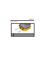
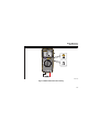
Fluke 101 Basic Digital Multimeter is a handheld, battery-powered device that can measure voltage, resistance, capacitance, and frequency. It has a large, easy-to-read display and is capable of measuring up to 6000 counts. The Fluke 101 is also equipped with a continuity tester and a diode test function. It is a versatile tool that can be used for a wide variety of electrical applications, from basic troubleshooting to more complex repairs.
Fluke 101 Basic Digital Multimeter is a handheld, battery-powered device that can measure voltage, resistance, capacitance, and frequency. It has a large, easy-to-read display and is capable of measuring up to 6000 counts. The Fluke 101 is also equipped with a continuity tester and a diode test function. It is a versatile tool that can be used for a wide variety of electrical applications, from basic troubleshooting to more complex repairs.


-
 1
1
-
 2
2
-
 3
3
-
 4
4
-
 5
5
-
 6
6
-
 7
7
-
 8
8
-
 9
9
-
 10
10
-
 11
11
-
 12
12
-
 13
13
-
 14
14
-
 15
15
-
 16
16
-
 17
17
-
 18
18
-
 19
19
-
 20
20
-
 21
21
-
 22
22
-
 23
23
-
 24
24
-
 25
25
-
 26
26
-
 27
27
-
 28
28


Fluke 101 Basic Digital Multimeter User manual
- Category
- Multimeters
- Type
- User manual
Fluke 101 Basic Digital Multimeter is a handheld, battery-powered device that can measure voltage, resistance, capacitance, and frequency. It has a large, easy-to-read display and is capable of measuring up to 6000 counts. The Fluke 101 is also equipped with a continuity tester and a diode test function. It is a versatile tool that can be used for a wide variety of electrical applications, from basic troubleshooting to more complex repairs.
Ask a question and I''ll find the answer in the document
Finding information in a document is now easier with AI