Page is loading ...

Via Luigi BARCHI 9/B – Reggio Emilia 42124 – Italy
Tel. +39 0522 345518 -Fax +39 0522 345551- mail info@adelsystem.com
www.adelsystem.com Instruction Manual FLEX UNI_R14_pag1.doc
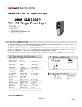
Output derating Curve
Continuous Load
0
20
40
60
80
100
120
140
160
-10 0 10 20 30 40 50 60 70 °C
%
FLEX Power Supplies 1, 2 and 3 Phase
Thank you for having chosen one of our products for your work.
We are certain the ADEL System Power Supplies will meet your
application requirements.
Application
The power supplies FLEX Series can be used in areas from
extreme industrial environment, and complies with the latest
technical standard. Before working with the unit, read these
instructions carefully and completely. All these power supplies
are single output, IP20, have Mounting DIN Rail IEC
60715/TH35. Class 1 isolation devices suitable for SELV and
PELV solutions.
Safety and warning notes
WARNING – Explosion Hazard Do not disconnect Equipment unless power has been switched off or
the area is known to be non-hazardous.
WARNING – Explosion Hazard. Substitution of components may impair suitability for class I, Division 2.
WARNING – Switch off the system before connecting the module. Never work on the machine when it
is live. The device must be installed in according with UL508. The device must have a suitable isolating facility
outside the power supply unit, via which can be switched to idle. Danger of fatal Injury!
Connection:
Cable Connection: The following cable cross-sections may be used:
Solid
(mm2) Stranded
(mm2) AWG Torque (Nm) Stripping
Length Power Supply
Input: 0.2 – 2.5 0.2 – 2.5 24 – 14 0.5 – 0.6 Nm 7 mm Others
4.0 6.0 30 – 10 0.8 – 1.0 Nm 7 mm Flex 500 series
Output: 0.2 – 2.5 0.2 – 2.5 24 – 14 0.5 – 0.6 Nm 7 mm Others
4.0 6.0 30 – 10 0.8 – 1.0 Nm 7 mm Flex 500 series
Signal: 0.2 – 2.5 0.2 – 2.5 24 – 14 0.5 – 0.6 Nm 7 mm Others
4.0 6.0 30 – 10 0.8 – 1.0 Nm 7 mm Flex 500 series
The connection is made by the screw type 2.5 mm2 (FLEX60-90-170-280 series) or 4.0 mm2 (FLEX500 series)
terminal blocks. Use only copper cables that are designed for operating temperatures of > 75 °C. Wiring terminal
shall be marked to indicate the proper connection for the power supply.
Input - Output power connection:
Input:
FLEXxxxxxA series 1 Phase Switching Power Supplies L, N, PE .
FLEXxxxxxB series 1Phase Switching Power Supplies L, N, PE .
FLEXxxxxxB series 2 Phase Switching Power Supplies L1, L2, PE .
FLEX500xxB series 3 Phase Switching Power Supplies L1, L2, L3, PE .
Output:
24 Vdc is made via the (+), (-).
1 Phase L N PE 1 Phase L NPE 2Phase 3 Phase
Signalling:
L
ed (Dc ok) status:
Jumper Setting
Output voltage OK: Lights up permanently Hiccup Mode / Manual Reset / Continuous Mode
Switch off, in overload and short circuit conditions Manual Reset / Continuous Mode
Blink, in overload and short circuit conditions Hiccup Mode
Parallel Connection, to Increase Output Power:
• Made parallel connection with same model of power supply to
increase the output power.
• Adjust the output approximately to the same value (± 20mV)
applying 1-2 A load to all devices output before connecting
them in parallel.
• Easy parallel connections Jumper. In FLEX280xxX and
FLEX500xxX for more power, you must change position of the
jumper to enable parallel connection. In this mode you can put
in parallel up to 4 power supply
Easy
Parallel connection
OFF(factory selection)
Easy Parallel connection ON
Parallel connection Redundancy:
Power supplies can be paralleled for 1+1 redundancy to obtain a
higher system availability. Redundant systems require a certain
amount of extra power to support the load in case one power supply
unit fails. The simplest way is to put two FLEX power supplies in
parallel. In case one power supply unit fails, the other one is
automatically able to support the load current without any
interruption. This simple way to build a redundant system has two
major disadvantages:
- The faulty power supply can not be recognized. The LED will still
be ON since it is reverse-powered from the other power supply.
It does not cover failures such as an internal short circuit in the secondary side of the power supply. In such a -
virtually nearly impossible - case, the defective unit becomes a load for the other power supplies and the output
voltage can not be maintained any more.
This can only be avoided by utilizing decoupling diodes which are included in the Redundancy Module MR220.
Recommendations for building redundant power systems:
a) Use separate input fuses for each power supply.
b) Monitor the individual power supply units. A DC-Led and Power Good Contact are already included on FLEX
power supplies. This feature reports a faulty unit; see power Good Section for any technical detail.
c) When possible, connect each power supply to different phases or circuits.
Serial connection:
a) It is possible to connect as many units in series as needed, providing the sum of the output voltage does not
exceed 150Vdc.
b) Voltages with a potential above 60Vdc are not SELV any
more and can be dangerous. Such voltages must be
installed with a protection against touching.
c) For serial operation use power supplies of the same
type.
d) Earthing of the output is required when the sum of the
output voltage is above 60Vdc.
e) Keep an installation clearance of 15mm (left/right)
between two power supplies and avoid installing the power
supplies on top of each other. Note: Avoid return voltage
(e.g. from a decelerating motor or battery) which is applied
to the output terminals.
Power Good Output Function
(No for FLEX60xxX)
Output are used for preventive function
monitoring of the power supply. An electrically isolated
signal contact is available. The signal contact Closes
when output power is OK and Opens when output voltage
falls below 20Vdc ±5%. This feature is particularly useful in redundant
applications.
Power Good Contact rating:
Max. DC1: 30 Vdc 1 A;
AC1: 60 Vac 1A Resistive load (EN 60947-4-1)
Min.:1mA at 5 Vdc Min permissive load
Protection:
On the primary side: the device is equipped whit an internal fuse; follow the next page table. If the internal fuse is
blown (fails opens), it is most probable that there is a fault in the device. If this failure occurs, the device must be
checked in the factory. Caution: in two phase Input models, Double pole / Neutral Fusing.
On the secondary side: the devices are electrically protected against: Over Load, Over Voltage Output (typ.35
Vdc), and Short circuit automatically.
Short circuit and overload Protections Mode:
Depending on the users application loads, the ADEL Flex Line offers three types of protection modes which are
available by removing the plastic window and changing the Jumper to the desired setting as shown below:
(No Settings jumper for FLEX60xxA only Continuous Mode Condition)
1) HICCUP MODE (default factory Jumper setting)
General purpose mode, used for normal load.
In case of short-circuit or overloading, the
output current is interrupted. The device tries
again to re-establish output voltage and normal
condition about every 2 second till the problem
is cleared. .
2) MANUAL RESET (manual Restart by Operator)
This protection mode is particularly suggested
in applications where safety procedures require
that reset be carried out only by an authorized
person.
In case of short-circuit or overload, the output
current is interrupted. In order to restart the
output it is necessary to switch-off the input
circuit for about 1 – 5 minutes. .
3) CONTINUOUS OUTPUT MODE
In case of short-circuit or overload, the output
current is kept at high values with near zero
voltage. In case of short circuit the current can
reach up to 3 times the rated current at 60°C.
This protection mode is used to meet the
requirements of demanding loads such as
motors, solenoid valves, lamps, PLC with highly
capacitive input circuits and other loads with
marked transient overload behavior
The output of the device is electrically protected against overload and short circuit. For the nominal voltage and
nominal current at temperature condition, please see technical data. The device can supply at the nominal Current
without switching off. As the overload increases, the output voltage is reduced until zero.
Temperature Ratings
Surrounding air temperature 50 °C for FLEX60xxA, for the
other 60°C. At the temperature of 70°C the output current will
be 75% - 50% of In. The equipment does not switch off in case
of ambient temperature above 70°C or thermal overload. The
devices are protected for Over temperature conditions “worst
case”; in this situations the device Shut-down the output and
automatic restart when temperature inside fall.
Standards and Certification
Electrical Safety:
Assembling device: UL508, IEC/EN 60950 (VDE 0805) and EN 50178 (VDE 0160).
Installation according: IEC/EN 60950.
Input / Output separation: SELV EN 60950-1 and PELV EN 60204-1. Double or reinforced insulation.
EMC Standards Immunity:
EN 61000-4-2, EN 61000-4-3, EN 61000-4-4, EN 61000-4-5.
EMC Standards Emission:
EN 61000-6-4, EN 61000-3-2,
Standards Conformity:
Safety of Electrical Equipment Machines: EN 60204-1.
The CE mark in According to EMC 2004/108/EC and Low voltage directive 2006/95/EEC
UL
Listed 508
Rail Mounting:
Assembly
Disassembly
Maximum angle assembly
Other models / modules must have a minimum vertical and horizontal distance of 10 cm to this power
supply in order to guarantee sufficient auto convection. Depending on the ambient temperature and
load of the device, the temperature of the housing can become very high!
Dimension and Lay-out:
-5° / +5° max
Output
Power Good
Easy Parallel
V adj
Vdc OK
Jumper Protection
Mode
Input
Input Select
Volta
ge

www.adelsystem.com
FLEX
power supply
TECHNICAL DATA
Model FLEX6024A FLEX9024A FLEX17024A FLEX28024A FLEX50024A FLEX9024B FLEX17024B FLEX28024B FLEX50024B
Wattage 40–70W 95–120W 120–180W 240–330W 480–600W 95–120W 120–180W 240–330W 480–600W
INPUT DATA 3 x Vac
Nominal Input Voltage / Tensione d’ingresso nominale 115 – 230Vac 115 – 230Vac
Input selectable
115 – 230Vac
Input selectable
115 – 230Vac
Input selectable
115 – 230Vac
Input selectable
230 – 400 – 500Vac
Input selectable
230 – 400 – 500Vac
Input selectable
230 – 400 – 500Vac
Input selectable
400 – 500Vac
Input Voltage Range / Campo di funzionamento 90 – 264Vac 90 – 135Vac
180 – 264Vac
90 – 135Vac
180 – 264Vac
90 – 135Vac
180 – 264Vac
90 – 135Vac
180 – 264Vac
187 – 264Vac
330 – 550Vac
187 – 264Vac
330 – 550Vac
187 – 264Vac
330 – 550Vac
330 – 550Vac
Inrush Current (Vn and In Load) I
2
t / Corrente di Inserzione ≤ 19 A ≤ 5msec ≤ 36 A ≤ 5msec ≤ 36 A ≤ 5msec ≤ 42 A ≤ 5msec ≤ 80 A ≤ 5msec ≤ 28 A ≤ 5msec ≤ 28 A ≤5 msec ≤ 34 A ≤5 msec ≤ 35 A ≤ 5 msec
Frequency /Frequenza di Ingresso 47 – 63 Hz 47 – 63 Hz 47 – 63 Hz 47 – 63 Hz 47 – 63 Hz 47 – 63 Hz 47 – 63 Hz 47 – 63 Hz 47 – 63 Hz
Input Current / Assorbimento 1.0 – 0.7A 1.8 – 0.9A 2.8 – 1.3A 3.3 – 2.2A 8.5 – 4.2 A 1.0 – 0.5 – 0.4A 1.5 – 0.8 – 0.7 A 2.2 – 1.4 – 1.0A 1,7A max
Internal Fuse / Fusibile Interno (non sostituibile) 4A 4A 4A 6.3A 10A 4A 4A 4A 6.3A
External Fuse (recommended)/ Fusibile Esterno raccomandato 6A 10A 10A 16A 16A 10A 10A 16 A 16A
OUTPUT DATA
Output Voltage Factory Setting ±3%/ Tensione di Uscita – (Vn) 24Vdc 24Vdc 24Vdc 24Vdc 24Vdc 24Vdc 24Vdc 24Vdc 24Vdc
Adjustment range / Campo di regolazione (Vadj) 22 – 27Vdc 22 – 27Vdc 22 – 27Vdc 22 – 27Vdc 22 – 27Vdc 22 – 27Vdc 22 – 27Vdc 22 – 27Vdc 22 – 27Vdc
Start up with capacitive load / Start up con carichi capacitivi ≤ 50.000µF ≤ 50.000µF ≤ 50.000µF ≤ 50.000µF ≤ 50.000µF ≤ 50.000µF ≤ 50.000µF ≤ 50.000µF ≤ 50.000µF
Turn-On delay after applying mains voltage /
Accensione con tensione di rete
1.5 sec. (max) 1 sec. (max) 1 sec. (max) 1 sec. (max) 1 sec. (max) 1 sec. (max) 1 sec. (max) 1 sec. (max) 1 sec. (max)
Continuous Current at 24 V < 40°C (In) / Corrente Continua 2.0A(115) – 3.0A(230) 5.0A 7.5A 14A 25A 5.0A 7.5A 14A 25A
Continuous Current at 24 V < 50°C (In) / Corrente Continua 1.5A(115) – 2.5A(230) 4.5A 6.0A 12A 22A 4.5A 6.0A 12A 22A
Continuous Current at 24 V < 60°C (In) / Corrente Continua – 4.0A 5.0A 10A 20A 4.0A 5.0A 10A 20A
Power Boost Current / Corrente di Boost (at 24Vdc 60°C ≥ 3min.) 3.5A 5.0A 7.5A 14A 25A 5.0A 7.5A 14A 25A
Current Max Oveload approx. 4Vdc (permanent) /
Corrente di sovraccarico (permanente)
Imax =
In 50°C x (1,8 – 2,2)
Imax =
In 60°C x (1,8 – 2,2)
Imax =
In 60°C x (1,8 – 2,2)
Imax =
In 60°C x (1,8 – 2,2)
Imax =
In 60°C x (1,8 – 2,2)
Imax =
In 60°C x (1,8 – 2,2)
Imax =
In 60°C x (1,8 – 2,2)
Imax =
In 60°C x (1,8 – 2,2)
Imax =
In 60°C x (1,8 – 2,2)
Short circuit current (Icc) / Corrente di corto circuito 7.0A 12A 16A 30A 60A 12A 16A 30A 60A
Hold-up Time ( min. Vac) 24Vdc / Tempo di arresto Typ. 20 msec Typ. 20 msec Typ. 20 msec Typ. 20 msec Typ. 20 msec Typ. 20 msec Typ. 20 msec Typ. 20 msec Typ. 20 msec
Residual Ripple / Ripple Residuo ≤ 80 mVpp ≤ 80 mVpp ≤ 80 mVpp ≤ 80 mVpp ≤ 80 mVpp ≤ 80 mVpp ≤ 80 mVpp ≤ 80 mVpp ≤ 80 mVpp
Efficiency (50% of In) / Rendimento tipico ≥ 85% ≥ 89% ≥ 89% ≥ 89% ≥ 90% ≥ 89% ≥ 89% ≥ 89% ≥ 91%
Dissipation power load max (W) / Potenza dissipata 6 11 17 28 54 11 17 28 54
CLIMATIC DATA
Ambient Temperature operation / Temperatura Ambiente di Lavoro -25 – +70°C -25 – +70°C -25 – +70°C -25 – +70°C -25 ÷ +70°C -25 ÷ +70°C -25 ÷ +70°C -25 ÷ +70°C -25 ÷ +70°C
De rating Tª > (In) / De rating Tª > (In) > 50° 2.5% °C > 60° 2.5% °C > 60° 2.5% °C > 60° 2.5% °C > 60° 2.5% °C > 60° 2.5% °C > 60° 2.5% °C > 60° 2.5% °C > 60° 2.5% °C
Ambient Temperature Storage / Temperatura max. Magazzino -40 ÷ +85°C -40 ÷ +85°C -40 ÷ +85°C -40 ÷ +85°C -40 ÷ +85°C -40 ÷ +85°C -40 ÷ +85°C -40 ÷ +85°C -40 ÷ +85°C
Humidity at 25 °C / Umidità 95% to 25°C 95% to 25°C 95% to 25°C 95% to 25°C 95% to 25°C 95% to 25°C 95% to 25°C 95% to 25°C 95% to 25°C
GENERAL DATA
Isolation Voltage (IN / OUT) / Tensione di Isolamento (IN / OUT) 3000Vac 3000Vac 3000Vac 3000Vac 3000Vac 3000Vac 3000Vac 3000Vac 3000Vac
Isolation Voltage(IN / PE) / Tensione di Isolamento(IN / TERRA) 1605Vac 1605Vac 1605Vac 1605Vac 1605Vac 1605Vac 1605Vac 1605Vac 1605Vac
Isolation Voltage(OUT / PE) / Tensione di Isolamento(OUT/TERRA) 500Vac 500Vac 500Vac 500Vac 500Vac 500Vac 500Vac 500Vac 500Vac
Protection Class (EN/IEC 60529) / Protezione Classe IP 20 IP 20 IP 20 IP 20 IP 20 IP 20 IP 20 IP 20 IP 20
Reliability (MTBF IEC 61709) / Affidabilità > 500 000 h > 500 000 h > 500 000 h > 500 000 h > 500 000 h > 500 000 h > 500 000 h > 500 000 h > 500 000 h
Pollution Degree Environment / Grado d'inquinamento ambientale 2 2 2 2 2 2 2 2 2
Connection Terminal Blocks Screw Type / Dimensione morsetti 2,5mm 2,5mm 2,5mm 2,5mm 4 mm 2,5mm 2,5mm 2,5mm 4 mm
Protection class (with PE connected) /
Grado di protezione (con cavo di terra collegato) I I I I I I I I I
Dimension (w-h-d)/Dimensioni (l-h-p) mm 50x120x50 mm 55x110x105 mm 55x110x105 mm 72x115x135 mm 85x120x140mm 55x110x105 mm 55x110x105 mm 72x115x135 mm 85x120x140mm
Weight / Peso 0.30 Kg approx 0.56 Kg approx 0.56 Kg approx 0.85 Kg approx 1.2 Kg approx 0.56 Kg approx 0.56 Kg approx 0.85 Kg approx 1.2 Kg approx
2 and 3Phase
(Input 230 – 400 – 500Vac)
1 Phase
(Input 115 – 230Vac)
2 x Vac 2 x Vac
All specification are subject to change without notice Data List FLEX UNI_R14_pag 2.xls
/