
October
1969
FORM:
IOM-
114A
Effective
with
serial
No.
N295574
MODEL
STOCK
NO.
M-180
900001
M-180P
900010
M-225
900019
M-225P
900
028
1
Astallation
IfiperatioN
~
E~1
aioteoance
Manual
mIIcr
ELECTRIC
MIGU
CO.
APPLETON,
WISCONSIN,
U.S.A.
54911
-
-
USt.
NWSA
CODE
NO.
4579


SECTION
1-
SAFETY
RULES
FOR
OPERATION
OF
ARC
WELDING
MACHINE
1.1.
GENERAL
DA.
These
rules
apply
to
ac
and
dc
welding
generators,
ac
transformer
and
ac/dc
welding
machines,
and
dc
transformer
rectifier
welding
machines.
DB.
In
arcwelding
operations,
where
electrically
en
ergized
parts
are
exposed,
observe
the
following
safety
rules
to
insure
maximum
personal
safety
and
protect
nearby
persons.
DC.
Failure
to
observe
these
safety
precautions
may
expose
not
only
you,
but
fellow
workers
as
well,
to
serious
injuries.
Once
these
rules
are
learned
and
kept
in
mind,
proceed
with
maximum
assurance.
WELDING
MACHINE
ciA.
Never
use
welding
cables
at
currents
in
excess
of
their
rated
capacity.
It
will
cause
overheating
and
rapid
deterioration
of
the
insulation.
It
is
also
uneconomical.
DONT
use
worn
or
poorly
connected
cables.
DB.
Inspect
the
cables
frequently.
Immediately
repair
all
breaks
in
the
insulation
with
rubber
and
friction
tapes.
Tighten
all
cable
connections
and
adequately
insulate
any
joints
where
a
connector
may
have
an
exposed
conductive
part.
In
addition
to
the
potential
hazard
to
life,
a
hazard
occurs
when
exposed
sections
of
cable
come
in
contact
with
grounded
metallic
objects,
causing
an
arc.
Unprotected
eyes
may
be
injured
and
fire
may
result
if
combustible
materials
such
as
oil
or
grease
are
in
the
vicinity.
The
efficiency
and
quality
of
welding
will
be
im
proved
by
elimination
of
these
dangerous
grounds,
and
by
keeping
connections
tight.
1.3.
ELECTRODE
HOLDER
DONT
use
electrode
holders
with
defective
jaws.
ciA.
Keep
the
jaws
of
the
electrode
holder
tight
and
the
gripping
surfaces
in
good
condition
to
provide
close
contact
with
the
electrodes.
Defective
jaws
will
permit
the
electrode
to
wobble,
making
control
of
the
welding
operations
difficult.
DONT
use
electrode
holder
with
loose
cablecon
nections.
Keep
the
connections
of
the
electrode
lead
to
the
holder
tight
at
all
times.
Use
only
fully
insulated
electrode
holders
(and
with
out
protruding
screwheads.)
Never
touch
two
electrode
holders
from
two
separate
welding
machines
at
the
same
time.
1.4.
CODE
CONFORMANCE
ciA.
The
machine
and
its
equipment
must
be
installed
and
maintained
in
accordance
with
the
National
Electrical
Code
and
local
requirements.
1.5.
PARALLEL
CONNECTIONS
ciA.
See
diagrams
in
the
instruction
manual
applying
to
the
welding
machine
used.
1.6.
POWER
DISCONNECT
SWITCH
DA.
If
the
welding
machine
does
not
include
a
power
disconnect
switch,
install
one
at
or
near
the
machine.
1.7.
POLARITY
SWITCH
DONT
operate
the
polarity
switch
under
load.
ciA.
The
polarity
switch
(when
supplied)
is
provided
for
changing
the
electrode
lead
from
positive
(reverse
polarity)
to
negative
(straight
polarity).
Never
move
it
while
under
the
load
of
a
welding
current.
Operate
this
switch
only
while
the
machine
is
idling
and
the
welding
circuit
is
open.
The
potential
dangers
of
opening
the
circuit
while
carrying
high
current
are:
0(1)
An
arc
will
form
between
the
contact
surfaces
of
the
switch
and
severely
burn
them.
0(2)
The
person
throwing
the
switch
may
receive
a
severe
burn
from
this
arcing.
1.8.
RANGE
SWITCH
DONT
operate
the
range
switch
under
load.
ciA.
The
range
switch
(when
supplied)
is
provided
for
obtaining
required
current
settings.
It
must
never
be
operated
while
the
machine
is
under
the
load
of
welding
current.
Operate
the
range
switch
only
while
the
machine
is
idling
and
the
welding
circuit
is
open.
Thepotenialdangerofswitchingthe
circuit
while
carrying
high
current
is
the
formation
of
an
arc
between
the
contact
surface
which
will
severely
burn
them.
Repeated
occurrences
of
this
arcing
will
eventually
prevent
operation
of
the
contacts.
1.9.
EXHAUST
GASES
DONT
use
gas
engine
units
in
confined
spaces
without
venting
the
exhaust
gases.
ciA.
If
gasoline
or
other
fuel
driven
welding
machines
are
operated
indoors,
provide
means
to
pipe
the
exhaust
gases
to
the
outside
air
to
avoid
carbon
monoxide
poisoning.
1.2.
WELDING
CABLES
DONT
overload
cables.
DB.
DC.
DD.
I
~1/
,--
I..
-
IOM-114A-
Page
1

DONT
use
welding
machine
without
grounding
frame
or
case.
I
_
I
DA.
Ground
the
ground
cable
of
every
power
circuit
to
prevent
accidental
shock
by
stray
current.
The
potential
danger
is
that
development
of
a
stray
cur
rent
may
give
a
fatal
shock
should
a
person,
for
example,
place
one
hand
on
thewelding
machine
and
the
other
on
the
switch
box,
or
other
grounded
equipment.
Do
not
ground
to
pipelines
carrying
gases
or
flammable
liquids
and
conduits
carrying
electrical
conductors.
Be
sure
conductors
can
safely
carry
the
ground
current.
When
con
necting
the
welding
machine,
properly
ground
the
machine
frame
or
case.
WELDING
OPERATIONS
1.11.
CONTAINERS
WHICH
HELD
COMBUSTIBLES
DONT
weld
on
containers
which
have
held
com
bustible
or
flammable
materials
or
materials
which,
when
heated,
give
off
flammable
or
toxic
vapors
without
proper
cleaning,
purging,
or
inerting.
DA.
Welding
on
containers
which
have
heldflammable
or
combustible
materials
may
be
extremely
danger
ous.
To
prevent
afireorexplosionof
the
container,
follow
the
recommendations
of
the
American
Weld
ing
Society
Pamphlet
A6.O
Welding
or
Cutting
Con
tainers
Which
Have
Held
Combustibles.
DONT
depend
on
your
eyes
or
nose
to
decide
if
it
is
safe
to
weld
on
a
closed
container.
DB.
Find
out
what
was
in
the
container
or
use
an
explosimeter.
A
very
small
amount
of
residual
flammable
gas
or
liquid
can
cause
a
serious
explosion.
NEVER
use
oxygen
to
ventilate
a
container.
DC.
When
you
know
the
container
held
a
gas
or
liquid
which
will
readily
dissolve
in
water:
D(1)
Flush
out
with
water
several
times
and
then
fill
with
water
as
far
as
work
permits,
posi
tioning
container
to
permit
introduction
of
as
much
water
as
possible.
D(2)
Before
welding
be
sure
there
is
a
vent
or
opening
to
provide
for
release
of
air
pressure.
EW.
When
you
know
the
container
held
a
gas
or
liquid
which
will
not
readily
dissolve
in
water.
D(1)
Clean
out
thoroughly
with
steam
or
a
cleans
ing
agent
and
purge
all
air
or
inert
with
a
gas
such
as
carbon
dioxide
or
nitrogen
before
re
pairing.
Carbon
dioxide
is
heavier
than
air
and
will
tend
to
remain
in
the
container
if
the
open
ing
is
at
the
top.
D(2)
Use
steam
to
clean
out
light
material.
D(3)
Use
a
strong
caustic
soda
solution
to
clean
out
heavy
oils
or
grease.
0(4)
Be
sure
to
purge
all
air
or
inert
with
a
gas,
such
as
nitrogen
or
carbon
dioxide,
no
matter
how
well
you
have
cleaned.
There
may
still
be
traces
of
oil,
grease,
or
other
readily
oxidizable
material
under
the
seams.
DE.
Be
careful
when
cleaning
with
steam
or
caustic
soda
wear
goggles
and
gloves.
DONT
clean
where
there
is
poor
ventilation.
OF.
Ventilation
is
necessary
to
carry
away
harmful
or
explosive
vapors.
DONT
clean
where
there
are
open
flames.
0G.
When
scraping
or
hammering
to
remove
heavy
sludge
or
scale,
use
a
spark
resistivetool
and
keep
it
wet
to
avoid
sparks.
OH.
Keep
your
head
and
arms
as
far
away
from
your
work
as
possible.
1.12.
HOLLOW
CASTINGS
DONT
weld
on
hollow
(cored)
castings
that
have
not
been
properly
vented.
The
casting
may
explode.
NEVER
weld
in
or
near
explosive
atmospheres,
Such
atmospheres
can
be
created
by
flammable
gas
leaks
or
by
vapors
from
flammable
liquids
(gasoline,
alcohol,
etc.)
or
by
combustible
dusts.
1.14.
VENTILATION
DONT
weld
in
confined
spaces
without
adequate
ventilation.
DA.
When
welding
in
confined
spaces,
provide
ventilation
in
accordance
with
United
States
of
America
Stand
ard
Z49.1,
1967.
Always
provide
adequate
ventila
tion
by
blowers,
air
lines,
or
other
acceptable
means.
Never
use
compressed
oxygen.
The
depletion
of
the
oxygen
supply,
the
heat
of
welding,
and
the
fumes
given
off
may
cause
severe
dis
comfort
or
a
serious
illness.
OB.
When
toxic
fumes
from
lead
or
cadmium
bearing
materials
or
any
other
substances
are
present
in
harmful
concentrations,
always
use
an
air
supplied
respirator.
L
--
J
--
1.10.
POWER
CIRCUIT
GROUND
1
_--I
1.13.
EXPLOSION
HAZARDS
Page
2

1.15.
SOLVENTS
DA.
Do
not
weld
where
chlorinated
hydrocarbon
vapors
from
degreasing,
cleaning,
or
spraying
may
reach
or
he
drawn
into
air
surrounding
the
welding
operation.
The
heat
of
the
arc
can
decompose
solvent
vapors
to
form
phosgene,
a
highly
toxic
gas
and
other
irritating
decomposition
products.
OB.
Do
not
weld
where
ultraviolet
lightfrom
the
electric
arc
can
penetrate
air
containing
even
minute
amounts
of
vapors
from
solvents
such
as
trichlo
roethylene
or
perchloroethylene.
Ultraviolet
light
can
decompose
the
vapors
to
form
phosgene,
a
highly
toxic
gas,
and
other
irritating
products.
1.16.
FIRE
HAZARDS
DONT
weld
near
flammable
or
combustible
materials.
DA.
Fires
can
be
caused
by
the
arc,
by
contact
with
the
heated
metal,
by
slag,
or
sparks.
Keep
com
bustibles
at
least
35
feet
from
the
arc
or
suitably
protected.
If
welding
must
be
done
in
a
particular
area,
move
the
combustibles
away.
If
they
cannot
be
moved,
cover
them
completely
with
fire
resistive
screens.
Cover
cracks
or
openings
in
floors
or
walls;
sweep
floor
free
of
combustibles
and wet
down,
if
wood,
being
sure
welder
wears
insulation
shoe
coverings.
Avoid
welding
on
partition
walls
in
contact
with
combustibles.
Heated
metal
on
the
other
side
of
partition
wall
being
welded
upon
can
ignite
combustibles
in
contact
with
the
partition.
Where
other
than
a
minor
fire
might
develop,
have
a
fire
watcher
stand
by
with
suitable
fire
extin
guishing
equipment
for
at
least
one-half
hour
after
the
welding
is
completed.
1.17.
ELECTRICAL
SHOCK-VOLTAGE
OPEN
power
circuits
before
checking
machines.
DA.
Before
working
on
the
wiring,
switches,
controls,
etc.,
open
the
power
line
disconnect
switch.
In
most
welding
shops
the
power
supply
used
for
arc
welding
machines
is
230
or
460
volts.
Open
circuit
voltages
are
usually
less
than
100
volts
and
welding
or
arc
voltage
drops
are
still
lower.
How
ever,
all
of
these
voltages
are
capable
of
developing
a
harmful
or
fatal
current
to
the
body.
DONT
touch
electrically
hot
parts.
DB.
Never
touch
any
exposed
or
non-insulated
part
of
the
cables,
cable
connectors,
clamps,
electrode
holders,
electrodes~
or
the
power
supply
equipment
to
prevent
harmful
or
fatal
electric
shock
or
burns.
1.18.
ELECTR
ICAL
SHOCK-DAMPNESS
NEVER
work
in
a
damp
area
without
suitable
in
sulation
against
shock.
Keep
hands,
feet,
and
clothing
dry
at
all
times.
DA.
To
pievent
harmful
body
shocks,
keep
hands,
feet
and
clothing
dry.
Never
stand
or
lie
in
puddles
of
water,
damp
ground,
or
against
grounded
metal
when
welding
without
suitable
insulation
against
shock.
Always
find
a
dry
board
or
rubber
mat
to
stand
on
when
water,
moisture,
or
perspiration
cannot
be
avoided.
Dampness
between
the
body
and
an
en
ergized
or
grounded
metallic
part
lowers
the
resistance
to
the
passage
of
current
to
the
body
which
may
produce
a
harmful
or
fatal
shock.
Salt
in
perspiration
or
sea
water
dangerously
1ower~
contact
resistances.
1.19.
STARTING
UNDER
LOAD
DONT
leave
an
uninsulated
electrode
holder,
or
a
live
electrode
on
the
table
topor
in
contact
with
a
grounded
metallic
surface.
When
it
is
not
in
use,
never
place
an
electrode
holder
in
contact
with
the
table
top
or
other
metallic
surface
in
contact
with
welding
ground.
Provide
an
insulated
hook
or
holder
for
the
electrode
holder.
A
potential
danger
is
that
a
holder
in
contact
with
the
ground
circuit
provides
a
dead
short
circuit
on
the
welding
machine.
If
the
machine
should
be
started
up,
this
short
circuit
would
cause
an
ex
cessive
load
on
the
machine
and
may
damage
the
insulation.
1.20.
FACE
PROTECTION
DONT
use
cracked
or
defective
helmets
or
shields.
Keep
the
helmet,
hand
shields,
or
face
shield
in
good
condition,
If
cracks
occur
in
the
fibre
material,
replace
the
shield,
since
the
leakage
of
arc
rays
may
cause
serious
burns.
1.21.
EYE
PROTECTION
NEVER
under
any
circumstances,
look
at
an
electric
arc
without
eye
protection.
CAUTION
Make
sure
that
flash
goggles
are
used
under
the
welding
helmet
at
all
times,
particularly
while
gas
shielded-arc
welding.
DA.
In
some
type
of
arc
welding,
such
as
gas
shielded-
arc
welding.ultraviolet
and
infrared
radiation
from
the
arc
is
particularly
intense
and
requires
constant
attention
to
avoid
arc
flashes
to
the
welder
when
striking
an
arc
and
to
avoid
exposure
to
other
welders.
NEVEB
strike
an
arc
without
ascertaining
that
nearby
persons
either
have
the
necessary
pro
tective
equipment
or
are
looking
in
the
opposite
direction.
DB.
For
welding
operations
in
open
areas,
provide
portable,
nonreflecting
screens
to
shield
persons
nearby
from
the
rays
of
the
arc.
Eye
burns
from
the
arc,
though
not
generally
permanent
injuries,
are
exceedingly
painful.
Such
burns
frequently
referred
to
as
flashes,
feel
like
hot
sand
In
the
eye.
For
eye
burns
consult
your
first
aid
station
or
doctor.
IOM-114A-Page
3

N
EVER
use
cracked,
ill-fitting,
or
defective
plates.
EC.
The
filter
glass
plate
provided
in
the
helmets
and
shields
must
be
of
reputable
manufacture
conform
ing
to
the
latest
USA
Standard
Z2.1.
Replace
cracked
or
ill-fitting
filter
plates
promptly.
NEVER
use
filter
plates
without
a
protecting
cover
glass.
ED.
Keep
a
clean
cover
glass
in
front
of
the
filter
plate
for
the
protection
thereof.
Frequent
renewal
of
these
cover
glasses
is
necessary,
since
they
become
covered
with
spatter,
reducing
vision.
1.22.
CLOTHING
NEVER
use
poor,
inadequate,
or
worn-out
cloth
ing.
Wear
heavy
shoes,
tightly
laced.
Keep
clothing
dry.
EA.
Proper
and
dry,
oil-free
clothing
is
essential
for
the
welders
protection.
Clothing
must
not
only
keep
off
the
spatter
and
molten
particles,
but
must
also
abstruct
the
rays
of
the
arc
and,
when
nec
essary,
insulate
the
body
from
harmful
electrical
currents.
EB.
Wear
leather
or
asbestos
gloves
at
all
times
to
protect
the
hands
and
wrists.
Dark
colored
shirts
are
preferred
to
light
ones
because
light
ones
reflect
arc
rays
to
exposed
parts
of
the
body.
In
the
case
of
gas
shieldedarc
welding,
light
colors
are
more
reflective
and
may
cause
eye
burns
due
to
the
intense
ultraviolet
rays
given
off
by
the
process.
Avoid
cotton
fabrics
when
gas
shielded
arc
welding.
EC.
An
arc
burn
on
the
skin
resembles
a
sunburn,
except
that
it
is
usually
more
severe.
Clothing
can
be
made
flame
resistant
by
treatment
with
a
solution
of
3/4
pound
of
sodium
stannate
in
1
gal
lon
of
water,
then
wrung
out
and
dipped
in
a
solution
of
1/4
pound
ammonium
sulphate
per
gal
lon
of
water.
Dont
wash
clothing
so
prepared
in
water,
but
dry
clean.
ED.
When
welding
operations
are
to
be
performed
in
vertical
and
overhead
positions,
leather
sleevelets,
aprons,
and
in
some
cases
leggings
and
ear
plugs
should
be
used
to
prevent
severe
burns
from
spatter
and
molten
metal.
1.23.
HOT
METAL
BURNS
NEVER
pick
up
hot
objects.
EA.
Never
pick
up
pieces
of
metal
which
welded
or
heated,
or
the
stub
ends
which
have
been
discarded.
1.24.
GRINDING
AND
CHIPPING
EA.
Whenever
it
is
necessary
to
grind
or
chip
metal,
wear
protective
goggles
specifically
designed
for
this
purpose.
Serious
eye
injuries
may
result
from
failure
to
wear
protective
goggles.
NEVER
do
any
chipping
or
grinding
without
pro
tective
goggles.
1.25.
COMPRESSED
GAS
CYLINDERS
NEVER
strike
an
arc
on
compressed
gas
cylin
ders.
EJA.
Avoid
accidental
contact
of
the
electrodes,
electrode
holder,
or
other
electrically
energized
parts
with
a
compressed
gas
cylinder
or
any
other
pressure
vessel.
Serious
accidents
or
fires
may
result.
EB.
Use
I.C.C.
cylinders.
They
are
manufactured
and
maintained
in
accordance
with
I.C.C.
requirements
and
are
safe
so
long
as
they
are
properly
handled.
Dont
drop
cylinders.
EC.
Identify
gas
content
by
the
name
marked
on
the
cylinder.
If
the
cylinder
is
unmarked,
do
not
use
it.
Return
it
to
the
supplier.
Do
not
rely
on
color
code.
ED.
Never
use
a
cylinder
or
its
contents
for
other
than
intended
purposes.
EE.
Keep
oil
and
grease
away
from
oxygen
cylinders
and
cylinder
valves.
EF.
Keep
cylinders
away
from
exposure
to
sparks,
hot
slag,
open
flame
and
all
possible
sources
of
ignition
or
excessive
heat.
EG.
Be
careful
that
cylinders
are
not
placed
so
as
to
become
a
part
of
an
electrical
circuit.
Avoid
third
rails,
wires
and
electric
welding
circuits.
EH.
When
transporting
cylinders
by
crane,
use
cradle,
platform
or
other
suitable
support.
El.
Never
lift
the
cylinders
by
slings,
by
the
caps
or
by
electric
magnets.
EJ.
Never
use
cylinders
as
supports
or
rollers.
EK.
Never
try
to
mix
any
gases
in
a
cylinder.
EL.
Never
try
to
refill
a
cylinder.
EM.
Mark
empty
cylinders
Empty
or
MT.
EN.
Send
Emptys
back
to
the
supplier
promptly.
EO.
Keep
Emptys
and
Fulls
separate.
EP.
Never
tamper
with
or
alter
cylinder
numbers
or
other
markings.
This
is
not
only
foolish
but
may
be
illegal.
EQ.
Do
not
tamper
with
or
change
fittings
on
cylinders.
ER.
If
valves
cannot be
opened
by
hand,
do
not
use
hammer
or
wrench.
Notify
supplier.
ES.
Protect
cylinder
valves
from
bumps,
falls,
falling
objects,
and
from
weather.
Keep
them
covered
with
cylinder
caps
when
moving
cylinders.
LIT.
Keep
valves
closed
on
empty
cylinders.
EU.
See
that
your
cylinders
are
clear
of
passageways
and
active
work
areas
and
that
they
are
secured
against
falling.
LIV.
If
adapter
is
required
between
cylinder
an~l
reg
ulator,
always
use
a
standard
adapter.
These
may
be
obtained
from
your
supplier.
Where
right
and
left
hand
threads
are
used
on
adapter,
use
two
wrenches
to
insure
leak
proof
connections.
EW.
Do
not
store
cylinders
in
unventilated
areas.
1/
~
have
just
been
of
electrodes
Page
4

SECTION
2-
INTRODUCTION
2-1.
GENERAL
This
manual
has
been
prepared
especially
for
use
in
familiarizing
personnel
with
the
design,
in
stallation,
operation
and
maintenance
ofthewelding
machine.
In
some
cases,
the
contents
of
this
pub
lication
are
generalized.
All
information
presented
in
this
manual
should
be
given
careful
consideration
to
assure
optimum
performance
and
service
of
the
equipment.
Process
information
is
available
by
contacting
your
welding
distributor.
2-2.
RECEIVING-HANDLING
To
prepare
the
welding
machine
for
installation,
several
items
should
be
checked.
Clean
all
packing
material
from
around
the
unit
and
carefully
inspect
for
damage
that
may
have
been
caused
by
shipping.
Any
claims
for
loss
or
damage
that
may
have
oc
curred
in
transit
must
be
filed
by
the
buyer
with
the
carrier.
Copy
of
bill
of
lading
and
freight
bill
will
be
furnished
on
request
ifoccasiontofileclaimarises.
Be
sure
to
read
all
the
instructions
before
at
tempting
to
operate
the
welding
machine.
When
requesting
information
concerning
the
weld
ing
machine,
be
sure,
to
furnish
serial
and
model
numbers.
2-3.
DESCRIPTION
This
welding
machine
is
designed
for
use
in
light
industrial
plants,
metal
fabrication
shops,
auto
motive
repair
shops
and
for
general
light
welding
applications.
Two
welding
current
ranges
are
available.
The
high
range
provides
ample
normal
open
circuit
volt
age
for
average
electrode
sizes.
The
low
range
pro
vides
maximum
open
circuit
to
permit
the
use
of
smaller
electrode
sizes.
The
180
amp
machine
uses
natural
updraft
cooling
and
the
225
amp
machine
uses
a
fan,
both
which
help
ensure
that
the
internal
components
are
kept
below
the
critical
operating
temperatures,
pro
viding
the
duty
cycle
ratings
are
not
exceeded.
2-4.
SAFETY
Before
attempting
to
make
primary
or
secondary
connections,
change
parts
or
make
repairs,
be
sure
the
welding
machine
is
completely
disconnected
from
the
main
power
line.
Before
the
welding
machine
is
put
into
operation,
read
the
complete
safety
section
at
the
front
of
this
manual.
This
will
help
avoid
any
possible
injury
due
to
misuse
or
improper
welding
applications.
SECTION
3
-
INSTALLATION
3-1.
LOCATION
(Figure
3-1)
Proper
component
operating
temperatures
on
the
225
amp
model
are
maintained
by
the
air
stream
produced
by
thefan
assembly.
On
the
180
amp
model
air
cooling
is
provided
by
means
of
natural
updraft
through
the
vented
bottom.
Therefore
the
air
passages
in
the front
and
bottom
of
the
welding
ma
chine
must
be
kept
open.
The
rear
of
the
welding
machine
should
be
kept
a
minimum
distance
of
18
inches
from
the
wall
to
help
ensure
proper
cooling.
The
location
should
be
such
that
a
minimum
amount
of
dust
and
dirt
will
be
drawn
into
the air
stream.
Preventive
maintenance
consists
of
re
moving
the
wrapper
and
blowing
out the
dust
ac
cumulation
inside
the
welding
machine,
For
this
reason
it
is
desirable
to
locate
the
unit
so
that
the
wrapper
can
be
removed
without
any
difficulty.
Four
mounting
holes
are
provided
in
the
welding
machine
base
for
machines
that
require
mounting.
Figure
3-1
gives
overall
dimensions
and
the
base
mounting
hole
layout
for
console
installation
or
other
installations
that
may
require
this
infor
mation.
3-2.
PRIMARY
CONNECTIONS
(Figure
3-2
&
3-3)
Most
rural
and
residental
power
systems
are
of
the
115/230
volt,
single
phase
type.
This
ac
arc
welding
machine
is
a
single
phase
unit
and
must
be
connected
to
a
single
phase
power
line.
Consult
the
local
power
and
light
company
if
there
is
any
question
about
type
of
system
used
locally
or
the
proper
connection
to
obtain
single
phase
power
service
to
the
welding
machine.
All
models
are
ordinarily
supplied
with
an
attach
ed
three
conductor
cable.
Models
requiring
208
or
230
volt
primary
input
are
equipped
with
a
three
prong
polarized
plug
and
wall
receptacle.
The
wall
receptacle
should
be
installed
in
a
con
venient
location
by
a
competent
electrician.
The
wall
receptacle
should be
installed
with
the
grounding
MODEL
WELDING
CURRENT
RANGE
AMPERES
RATED
CURRENTOUTPUT
AT25
VOLTS.
20%
DUTY
CYCLE
CURRENT
OUTPUT
AT3OVOLTS.
20%
DUTY
CYCLE
OPEN
CIRCUIT
VOLTS
POWER
INPUT
AT
RATED
LOAD
50/60
Hz.
AMPERES
23OVOLTS
SINGLE
PHASE
kw
kva
DIMENSIONS
OVERALL
WEIGHT
HEIGHT
WIDTH
DEPTH
NET
SHIPPING
180
Amp.
180
Amp.
*
225
Amp.
225
Amp.
*
20-180
20-180
30-225
30-225
180
180
225
225
200
200
55180
55/80
55/80
55/80
37
30
44.4
38.5
5.4
5.4
7.2
7.2
8.5
6.9
10.2
8.8
17
12-1/2
20-1/2
130
Lbs.
138
Lbs.
17
12-1/2~~
20-1/2~
135
Lbs.
142
Lbs.
17
12-1/2
20-1/2
135
Lbs.
142
Lbs.
17
12-1/2~
20-1/2~~
140
Lbs.
147
Lbs.
~With
Power
Factor
Correction.
Figure
2-1.
Specifications
Figure
3-1.
Dimensional
Drawing
AA-500
001-1
IOM-114A-
Page
5

terminal
at
the
top
as
this
then
permits
the
power
cord
to
hang
downward
without
undue
bending
or
twisting.
Models
with
other
than
230
volt
only
primary
input
voltages,
are
equipped
with
a
voltage
changeover
terminal
strip
and
two
jumper
links.
This
terminal
strip
is
accessible
by
opening
the
access
door
on
the
rear
panel.
The
terminal
strip
is
located
at
the
rear
of
the
welding
machine
base.
If
the
welding
machine
is
furnished
with
a
pri
mary
voltage
changeover
terminal
strip,
connect
the
jumper
links
to
the
indicated
voltage
terminals
to
match
the
primary
input
voltage.
Whenever
only
one
jumper
link
connection
is
necessary
for
the
proper
input
voltage,
connect
both
jumper
links
across
the
same
two
terminals.
This
will
help
prevent
losing
the
second
jumper
link.
Refer
to
Figure
3-2
for
proper
jumper
link
connections.
Welding
machines
are
shipped,
unless
otherwise
ordered,
with
the
jumper
links
connected
in
the
highest
voltage
position.
This
welding
machine
should
be
operated
from
a
separately
fused
or
circuit
breaker
protected
cir
cuit.
The
maximum
capacity
of
the
welding
machine
is
affected
by
the
line
voltage
and
if
the
circuit
is
overloaded,
the
performance
of
the
welding
machine
will
be
impaired.
Install
a
cable
of
two
primary
wires
plus
one
ground
wire
(see
Table
3-1
for
proper
wire
and
fuse
sizes)
from
the
line
disconnect
switch
or
circuit
breaker
to
the
WALL
RECEPTACLE.
See
Figure
33.
For
models
without
a
three
prong
plug,
a
60
am
pere
plug
may
be
installed
to
the
welding
machine
primary
input
cable
and
the
receptacle
to
the
line
disconnect
switch.
A
grounding
wire
must
be
run
to
a
suitable
ground
ing
medium
such
as
the
electrical
conduit
system,
the
water
system
or
a
regular
driven
ground
rod.
Check
with
the
local
inspection
authority
if
there
is
any
question
as
to
an
accepted
grounding
method.
Models
with
a
three
prongpolarizedplug,plugin
to
the
wall
receptacle.
For
models
without
a
three
prong
plug,
connect
the
No.
10
green
wire
to
the
ground
wire
or
connection
in
the
line
disconnect
switch
and
the
two
No.
8
wires
to
the
power
leads.
3-3.
SECONDARY
(WELDING)
CONNECTIONS
It
is
recommended
that
the
welding
cables
be
kept
as
short
as
possible,
placed
close
together
and
be
of
adequate
current
carrying
capacity.
The
resistance
of
the
welding
cables
and
connections
cause
a
volt
age
drop
which
is
added
to
the
voltage
of
the
arc.
Excessive
cable
resistance
may
result
in
over
loading
as
well
as
reducing
the
maximum
current
output
of
which
the
welding
machine
is
capable.
When
welding
with
ac,
longer
cables
if
coiled
up,
will
generate
a
magnetic
field
that
can
reduce
the
output
of
the
welding
machine.
The
welding
cables
from
the
work
and
electrode
holder
to
the
welding
machine
should
be
taped
together
at
short
intervals.
The
proper
operation
of
any
arc
welding
machine
is
to
a
great
extent
dependent
on
the
use
of
welding
cables
and
connections
that
are
in
good
condition
Table
3-2.
Secondary
Welding
Cable
Size
WELDING
AMPERES
TOT
AL
LENGTH
OF
CABLE)
COPPER)
IN
WELD
CIRCUIT
50
100 150
200
250
300
100
2
2
1
1/0
2/0
3/0
150
2
1
2/0
3/0
4/0
200
2
1/0
3/0
4/0
250
2
2/0
4/0
300
1
3/0
NOTE:
A.
50
FEETOR
LESS
B.
CABLE
SIZE
IS
BASED
ON
DIRECT
CURRENT
(DC),
20%
DUTY
CYCLE
AND
EITHER
A
4
VOLTS
OR
LESS
DROP
OR
A
CURRENT
DENSITY
OP
NOT
OVER
300
CIRCULAR
MILS
PER
AMP.
C.
WELD
CABLE
INSULATION
WITH A
VOLTAGE
RATING
TO
WITH
STAND
THE
OPEN
CIRCUIT
VOLTAGE
IO.C.V.)
OF
THE
WELD
ING
MACHINE
MUST
BE
USED.
WHILE
MOST
WELDING
MA
CHINES
HAVE AN
OPEN
CIRCUIT
VOLTAGE
OP
LESS
THAN
100
VOLTS,
SOME
WELDING
MACHINES
OF
SPECIAL
DESIGN
MAY
HAVE
HIGHER
OPEN
CIRCUIT
VOLTAGE.
~~1
Table
3-1.
Recommended
Primary
Wire
And
Fuse
Sizes
MODEL
PRIMARY
WIRE
SIZE
(From
source
to
line
disconnect
switch)
FUSE
SIZE
(AMPERES)
115V
208V
230V
460V
575V
115V
208V
230V
460V
575V
180
Amp
Model
Without
P.F.C.
180
Amp
Model
With
P.F.C.*
225
Amp
Model
Without
P.F.C.
225
Amp
Model
With
P.F.C.
No.
2
(No.
6)
No.4
(No.6)
No.
2
(No.
6)
No.3
(No.6)
No.
6
(No.
8)
No.8
(No.8)
No.
6
(No.
8)
No.6
(No.8)
No.
8
(No.
8)
No.
10
(No.
10)
No.
6
(No.
8)
No.8
(No.
8)
No.
12
(No.
12)
ND.
14
(No.
14)
No.
10
(No.
10)
No.
12
(No.
12)
No.
14
(No.
14)
No.
14
(No.
14)
No.
12
(No.
12)
No.
12
(No.
14)
150
110
175
150
80
70
100
80
70
60
90
75
35
30
45
35
30
25
35
30
Numbers
in
I
4
are
ground
mire
sizes.
Pomer
Factor
Correction.
AA-900
B23-9
Figure
3-3.
Primary
Connections
iee
SzS
voits
ate
voLts
373
VOLtS
:
A-BOO
g23-e
Figure
3-2.
Primary
Voltage
Link
Arrangement
Page
6

and
of
adequate
size.
Electrode
holder
and
ground
clamp
should
be
at
least
200
ampere
capacity
and
securely
connected
to
the
welding
cables.
An
in
sulated
electrode
holder
must
be
used
to
ensure
operators
safety.
Select
the
proper
size
welding
cable
from
Table
3-2.
A.
Jack
Plug
Installation
(Figure
3-4)
Two
jack
plugs,
enclosed
in
a
cloth
bag,
are
fur
nished
with
the
welding
machine.
Follow
instruc
tions
carefully
for
proper
installation
of
the
jack
plugs
to
the
welding
cables.
See
Table
32
for
proper
welding
cable
sizeS
Standard
jack
plugs
furnished
with
unit
will
accommodate
cable
sizes
ranging
from
6
to
1.
1.
Remove
3/4
inch
of
insulation
from
one
end
of
each
welding
cable.
2.
Clamp
the
welding
cable
in
a
vise
with
the
un
insulated
end
protruding
upward
out
of
the
vise
approximately
1-3/4
inches.
3.
Place
the
steel
tie
wire
(A)
approximately
1/4
inch
from
the
end
of
the
insulation.
4.
Make
a
half
turn
around
the
cable
bringing
the
looped
ends
of
the
tie
wire
together.
5.
Insert
a
rod
of
approximately
3/8
inch
diameter
through
the
two
looped
ends
of
the
tie
wireS
6.
Twist
the
tie
wire
(B)
until
the
entire
tie
wire
is
twisted
and
is
tight
around
the
insulation
of
the
welding
cable.
7.
Clip
off
the
looped
ends
of
the
tie
wireS
8.
Bend
the
twisted
tie
wire
over
alongthe
side
(C)
of
the
uninsulated
portion
of
the
welding
cable.
9.
Wrap
the
strip
of
copper
foil
tightly
around
the
uninsulated
end
of
the
welding
cable
and
the
twist
ed
tie
wire
(D).
10.
Place
the
jack
plug
on
the
end
of
the
welding
cable
and
push
it
onto
the
welding
cable
over
the
copper
foil
(E).
11.
Insert
the
1/4-20
allen
set
screws
into
the
center
CAUTION
cfl~
Figure
3-4.
Jack
Plug
Installation
and
upper
holes
in
the
jack
plug
and
tighten.
12.
Remove
the
welding
cable
from
the
vise
and
in
sert
the
jack
plug
into
the
fiber
sleeve.
Slide
the
fiber
sleeve
over
the
jack
plugandweldingcahle
until
the
hole
in
the
fiber
sleeve
lines
up
with
the
8/32
hole
in
the
jack
plug
(F).
13.
Insert
the
8/32
self
tapping
screw
through
the
hole
in
the
fiber
sleeve
into
the
jack
plug.
Tighten
the
screw
with
a
screw
driver.
Connect
a
Work
Clamp
to
one
of
the
unused
ends
of
one
of
the
cables.
Connect
an
Electrode
Holder
to
the
unused
end
of
the
other
welding
cable.
The
method
of
connecting
the
cables
to
the
work
clamp
and
electrode
holder
will
depend
on
the
manu
facturers
design.
SECTION
4
-
OPERATION
I
Never,
under
any
circumstances,
operate
the
weld
ing
machine
with
the
cover
removed.
In
addition
to
a
safety
hazard,
improper
cooling
may
result
in
damage
to
the
welding
transformer
and
the
welding
machine
components.
Be
sure
to
read
the
complete
safety
section
at
the
front
of
the
manual
before
oper
ating
the
welding
machine.
20
30
40
50
60
7080
100
%
DUTY
CYCLE
A-101
391A
Figure
4-1.
Duty
Cycle
Chart
4-1.
DUTY
CYCLE
(Figure
4-1)
The
duty
cycle
of
a
welding
machine
is
the
percentage
of
a
ten
minute
period
that
the
welding
machine
can
operate
safely
at
a
given
output.
This
welding
machine
is
rated
at
a
20
percent
duty
cycle.
This
means
that
the
welding
ma
chine
can
operate
safely
at
rated
load
if
the
ma
chine
is
on
for
no
more
than
two
minutes
and
off
for
eight
minutes.
If
the
output
is
increased
above
rated
load,
the
duty
cycle
must
be
reduced.
Figure
4-1
shows
the
percent
duty
cycle
compared
to
output.
This
chart
should
be
used
for
reference
by
the
operator
to
de
termine
the
operating
limits
or
ON
time
of
the
weld
ing
machine
if
it
is
operated
above
rated
output.
4-2.
OPEN
CIRCUIT
VOLTAGE
This
welding
machine
provides
80
volts
open
circuit
on
the
ac
LOW
range
and
55
volts
open
cir
cuit
on
the
ac
HIGH
current
range.
Open
circuit
voltage
is
the
voltage
present
between
the
electrode
and
work
before
an
arc
has
been
struck.
4-3.
ARC
VOLTAGE
Arc
voltage
is
the
voltage
between
the
electrode
and
work
while
a
welding
arc
is
being
maintained.
Two
open
circuit
voltages
permit
the
use
of
larger
electrodes
demanding
high
welding
amperages
with
minimum
power
requirements.
The
higher
open
cir
cuit
voltage
enables
the
welder
to
use
small
dia
meter
electrodes,
stainless
steel,
low
hydrogen
and
other
hard
to
run
electrodes
with
complete
satis
faction.
I I
FPL
~jI
AA-901
024-4
i/
U)
a
Li
cc
Li
£
0
C
U
Lii
I
225
200
175
150
125
100
go
80
0
IOM-114A-
Page
7

90
80
70
60
(#1
-J
0
40
C
30
20
10
0
cuit
voltage
to
reduce
power
demand.
The
LOW
ampere
range
utilizes
a
high
open
cir
cuit
voltage
to
assure
arc
flexibility
and
it
is
always
recommended
that
the
LOW
range
be
used
for
hard
surfacing,
alloy
application,
and
small
electrodes
where
the
average
current
used
is
155
or
less.
4-6.
FINE
CURRENT
CONTROL
Select
the
desired
welding
current
within
the
range
by
rotating
the
Fine
Current
Adjustment
Control
on
the
front
of
the
welding
machine.
A
current
indicator
on
the
upper
left
part
of
the
control
panel
shows
the
current
in
accordance
with
thecurrentrangeinuse.
4-7.
ON-OFF
POWER
SWITCH
The
Power
switch
controls
the
primary
line
power
to
the
welding
transformer.
When
the
switch
is
placed
in
the
ON
position,
open
circuit
voltage
will
be
impressed
across
the
Work
and
Electrode
re
ceptacles.
4-8.
SHIELDED
METAL-ARC
(SMAW)
WELDING
(Figure
4-3)
This
welding
machine
will
handle
all
good
quality
mild
steel,
ac
and
ac/dc
electrodes
from
5/64
to
3/16
diameter
with
the
exception
of
low
hydrogen
and
iron
powder
coated
electrodes.
Iron
powder
coating
requires
higher
arc
voltages
for
the
given
current.
The
use
of
iron
powder
coated
electrodes
in
the
excess
of
5/32
diameter
is
not
recommended
for
this
model
welding
machine.
The
high
open
circuit
voltage
of
80
volts
available
on
the
low
ac
current
range
of
this
welding
machine
makes
it
possible
to
use
some
of
the
so-called
hard
to
run
electrodes
such
as
stainless
steel
and
low
hydrogen
up
to
3/32
and
possibly
1/8
diameter.
4-4.
VOLT-AMPERE
CURVES
(Figure
4-2)
The
volt-ampere
curves
show
the
output
volt
age
available
at
any
given
output
current
within
the
limits
of
the
minimum
and
maximum
current
control
setting
on
each
range.
With
the
use
of
the
volt-am
pere
curves,
it
is
possible
to
determine
the
am
perage
required
for
a
particular
load
voltage.
In
metallic
arc
or
coated
electrode
welding,
it
is
impossible
for
the
operator
to
hold
an
arc
length
which
does
not
vary.
This
varyingarc
length
causes
arc
voltage
to
vary
which
in
turn
produces
core
sponding
changes
in
welding
current.
The
steeper
the
slope
of
the
volt-ampere
curve
within
the
weld
ing
range,
the
lower
the
current
change
for
a
given
voltage
change.
4-5.
CURRENT
RANGES
The
HIGH
ampere
range
utilizes
a
low
open
cir
1,
Insert
the
jack
plug
from
the
Work
Welding
Cable
into
the
WORK
receptacle
and
clamp
the
opposite
end
of
the
Work
Cable
to
the
work-
piece.
2.
Insert
the
Electrode
Holder
welding
cable
jack
plug
into
either
the
Electrode
LOW
or
HIGH
receptacle.
A
slight
twist
while
inserting
the
jack
plugs
into
the
receptacles
will
ensure
a
tight
connection.
If
the
required
current
is
in
both
ranges,
use
the
LOW
range
receptacle
as
this
will
provide
better
current
control.
3.
Turn
the
Fine
Current
Adjustment
Control
to
the
desired
welding
current.
4.
Place
the
Power
switch
In
the
ON
position.
5.
Place
an
electrode
of
proper
type
and
size
into
the
Electrode
Holder
and
commence
welding.
6.
Readjust
the
current
control
if
necessary.
7.
After
the
welding
job
is
completed,
break
the
arc
and
place
the
Power
switch
in
the
OFF
position.
4-9.
ARC
TORCH
OPERATION
A
carbon
arc
torch
may
be
usedwith
this
welding
machine.
With
a
carbon
arc
torch
it
is
possible
to
weld
and
braze
metals
that
ordinarily
are
considered
weldable
only
by
the
oxyacetylene
method.
Itis
es
pecially
adaptable
for
brazing,
soldering,
pre
heating
and
hard
surfacing.
A
carbon
arc
torch
maintains
a
high
temperature
arc
between
two
car
bons.
Welds
produced
with
this
type
of
torch
are
sound,
strong,
and
free
from
porosity.
The
parent
metal
or
welding
rod
is
used
as
a
filler.
25
50
75
100
125 150
175
200
225
AC
AMPERES
180
AMP
MODEL
96-900
001-1
90
80
70
60
~
50
-a
0
>
40
U
C
30
20
10
0
50
100
150
200
250
300
AC
AMPERES
225
AMP
MODEL
EB-900
019-1
Figure
4-2.
Volt-Ampere
Curves
AA-900
001-2
Figure
4-3.
AC
Welding
Connections
4
Page
8

SECTION
5-
MAINTENANCE
I
I
1~~
Be
sure
the
branch
circuit,
main
disconnect
switch
or
circuit
fuses
are
removed
before
attempting
any
inspection,
or
work
on
the
inside
of
the
welding
ma
chine.
Placing
the
Power
switch
on
the
welding
ma
chine
in
the
OFF
position,
does
not
remove
voltage
from
the
power
terminal
inside
of
the
machine.
5-1.
TRANSFORMER
Occasional
blowing
out
the
dust
and
dirt
from
a-
round
the
transformer
is
recommended.
This
should
be
done
periodically
depending
upon
the
location
of
the
Unit
and
the
amount
of
dust
and
dirt
in
the
at
mosphere.
A
clean
dry
air
stream
should be
used
for
this
cleaning
operation.
5-2.
FAN
MOTOR
(225
Amp
Models
Only)
The
fan
motor
bearings
are
of
OIL
LITE
con
struction.
Apply
a
few
drops
of
light
machine
oil
to
the
two
oil
cups
on
the
fan
motor
once
a
year.
Be
sure
not
to
over
oil.
Excess
oil
may
get
on
the
power
transformer
windings
and
may
damage
the
insulation
of
the
transformer
winding.
5-3.
MOVABLE
SHUNT
Approximately
once
a
year,
it
may
be
necessary
to
lubricate
the
lead
screw,
guides
and
shunt
slide.
Apply
a
light
coat
of
fairly
high
temperature
grease,
taking
care
to
avoid
getting
grease
on
any
other
part
of
the
welding
machine.
Use
SOCONY
BBB
high
temperature
grease
or
equipvalent.
SECTION
6
-
TROUBLESHOOTING
A.
TROUBLE:
No
Output
or
welding
current.
PROBABLE
CAUSE:
1.
Blown
line
fuses.
Bad
or
open
POWER
switch.
C.
TROUBLE:
High
Output
PROBABLE
CAUSE:
1.
Check
line
voltage.
2.
Check
position
of
JUMPER
links
on
PRIMARY
In
put
terminal
board
if
so
equipped.
B.
TROUBLE:
Erratic
welding
current.
PROBABLE
CAUSE:
1.
Loose
connection
on
POWER
switch,
JACK
re-
ceptacles
or
POWER
cord.
2.
Bad
or
damp
electrodes,
D.
TROUBLE:
Low
Output.
PROBABLE
CAUSE:
1.
Check
line
voltage.
2.
Check
position
of
JUMPER
links
on
PRIMARY
In-
put
terminal
board
if
so
equipped.
NO.
8-A
RUNNING
GEAR
Has
four
5
solid
rubber
tire
wheels
which
bolt
to
the
frame
of
the
welding
machine.
Towing
handle
bolts
to
the
recessed
front
panel
and
conveniently
folds
into
the
recessed
portion
of
the
front
panel
when
not
in
use.
NO.
21C2
RUNNING
GEAR
Four
21/2
ball
bearing
steel
wheel
swivel
casters
which
bolt
to
the
frame
of
the
welding
machine.
No
towing
handile
supplied
with
this
running
gear.
CAUTION
I;
L
80
AMPERE
LIMITED
INPUT
AC.
WELDER
POWER
FACTOR
CORRECTION
-OPTIONAL
POWER
CORD
I
PLUG
225
AMPERE
LIMITED
INPUT
A,C
WELDER
ROWER
FACTOR
CORRECTION
-
OPTIONAL
Circuit
Diagram
No.
A-408-F1
SECTION
7-
OPTIONAL
EQUIPMENT
Circuit
Diagram
No.
A-522-A2
Figure
7-1.
8-A
Running
Gear
AA.040
031-1
IOM-114A-Page
9

Metal
arc
welding
with
the
transformer
welding
machine
depends
upon
the
fundamental
fact
that
when
one
side
of
the
welding
circuit
is
attached
to
a
piece
of
steel,
a
welding
electrode
connected
to
the
other
side
and
the
two
brought
into
contact,
an
arc
will
be
established.
If
the
arc
is
properly
controlled,
the
metal
from
the electrode
will
pass
through
the
arc
and
be
deposited
on
the
steeL
When
the electrode
is
moved
along
the
steel
at
the
correct
speed,
the
metal
will
deposit
in
a
urn-
form
layer
called
a
bead.
The
electrodes
used
in
welding
are
carefully
manufactured
to
produce
strong,
sound
welds.
They
consist
of
a
core
of
steel
wire,
usually
called
mild
since
it
contains
a
low
(0.10.
0.14)
percentage
of
carbon.
Around
this
core
is
applied
a
special
coating
which
assists
in
cre
ating
the
arc
and
at
the
same
time
protects
the
molten
steel
as
it
transfers
across
the
arc.
In
order
to
utilize
these
principles
in
metal
arc
welding,
some
means
of
controlling
the
power
is
essential.
The
power
in
a
welding
circuit
is
mea
sured
by
the
voltage
and
current.
However,
the
voltage
is
governed
by
the
arc
length
and
in
turn
depends
on
the
electrode
diameter.
Therefore,
the
practical
measure
of
the
power,
or
heat,
is
in
terms
of
the
current,
generally
measured
in
amperes.
Obviously
a
small
electrode
requires
less
current
than
a
large
one.
To
simplify
operations
the
scale
on
the
front
of
the
welding
machine
is
marked
off
for
the
various
current
values.
The
exact
current
selected
for
a
job
depends
upon
the
size
of
the
pieces
to
be
welded
and
the
position
of
welding.
Generally
a
lower
current
will
be
sufficient
for
welding
on
a
small
part
than
would
be
necessary
to
weld
on
a
large
piece
of
the
same
thickness.
Similarly
with
a
given
size
of
electrode
a
lower
current
should
be
used
on
thin
metals
than
on
the
heavier
sections.
BUTT
FLAT
POSITION
W(LDS
Figure
1.1
While
it
is
always
a
good
policy
to
weld
on
work
in
the
Nat
position,
as
shown
in
Figure
1.1,
occasionally,
when
working
on
machines
or
other
large
units
it
will
be
necessary
to
weld
in
a
ver
tical,
horizontal
or
overhead
position
as
shown
in
Figures
1.2,
1.3,
and
1.4,
respectively.
Generally,
under
these
difficult
conditions
it
is
helpful
to
reduce
the
current
from
the
value
used
on
weld.
ing
in
the
flat
position,
OVERH(AD
POSITION
WELDS
Filth
Figure
1.4
STRIKING
THE
ARC
-
RUNNING
BEADS
In
learning
to
weld
there
are
certain
funda
mental
steps
which
must
be
mastered
before
one
can
attempt
to
weld
on
actual
work.
Preparatory
to
the
actual
striking
of
an
arc,
it
is
necessary
to
insert
the electrode
in
the
holder,
as
shown
in
Figure
2.1.
For
striking
an
arc,
Figure
3.1
illus
trates
what
is
commonly
knowing
as
the
scratch
ing
technique.
In
this
method
the
striking
end
of
the
electrode
is
dragged
across
the
work
in
a
manner
much
the
same
as
striking
a
match.
When
the
electrode
touches
the
work,
the
welding
cur
rent
starts.
If
held
in
this
position,
the
electrode
would
freeze
or
weld
itself
to
the
work
and
to
overcome
this,
the
electrode
is
withdrawn
from
the
work
immediately
after
contact
has
been
PRINCIPLES
OF
ARC
WELDING
BUTT
VERTICAL
POSITION
WELDS
FILLET
Figure
1.3
BUTT
(
Figure
2.1
\
//
II
BUTT
HORIZONTAL
POSITION
WELOS
FILLET
Figure
1.2
Figure
3.1
Page
10

a-
made.
The
amount
that
the
electrode
is
with
drawn
is
small
and
depends
upon
the
diameter;
this
distance
is
known
as
the
arc
length.
If
in
striking
an
arc,
the
electrode
freezes,
it
may
be
freed
by
a
quick
twist
of
the
wrist.
Another
method
of
establishing
the
arc
is
avail
able.
It
is
known
as
the
tapping
method
and
is
shown
in
Figure
4.1.
In
this
the
electrode
in
the
holder
is
brought
straight
down
on
the
work
and
immediately
after
contact,
is
withdrawn
to
the
proper
arc
length.
Practice
striking
the
arc
using
both
methods.
Generally
the
scratching
method
is
preferred
for
a-c
welding.
Determination
of
the
correct
arc
length
is
diffi
cult
since
there
is
no
ready
means
of
measuring
it.
As
a
preliminary
guide,
use
about
1/16
arc
length
on
1/16
and
3/32
electrode;
for
1/s
and
5/32
electrodes
use
about
1/8
arc
length.
When
skill
is
acquired,
the
sound
of
the
arc
will
be
a
good
guide.
A
short
arc
with
correct
current
will
give
a
sharp,
crackling
sound.
Once
the
knack
of
starting
and
holding
an
arc
has
been
learned,
turn
next
to
depositing
weld
metal.
In
the
beginning
it
is
best
to
run
beads
of
weld
metal
on
flat
plates
using
a
full
electrode.
Practice
moving
from
left
to
right
and
from
right
to
left.
The
electrode
should
be
held
more
or
less
perpendicular
to
the
work,
except
that
tilting
it
ahead,
in
the
direction
of
travel
will
prove
help
ful.
The
correct
position
is
shown
in
Figure
5.1.
SPATtER
A
proper
bead
is
shown
in
Figure
6.1
while
Figure
7.1,
illustrates
a
cross-section
through
the
bead
and
identifies
the
various
terms
used
in
describ
ing
a
weld.
To
produce
these
results
it
is
neces
sary
to
hold
a
short
arc,
travel
at
a
uniform
speed,
and
feed
the
electrode
downward
at
a
constant
rate
as
it
melts.
BEAD
BUILD
UP
PENETRATION
GOOD
Probably
the
first
attempts
in
the
practice
will
fall
short
of
the
results
shown.
Too
long
an
arc
will
be
held
or
the
travel
speed
will
vary
from
slow
to
fast
and
the
welds
will
look
like
the
one
in
Figure
8.1.
A
cross
section
through
such
a
weld
SPATTER
is
given
in
Figure
9.1.
In
addition
the
weld
will
probably
be
spongy
(porous)
and
of
low
strength.
Continue
practicing
until
uniform
beads
as
shown
in
Figure
6.1
can
be
produced
every
time.
A
good
method
of
practicing
is
to
deposit
a
series
of
beads,
one
next
to
the
other
until
the
plate
is
covered.
Then
deposit
another
series
of
beads
at
right
angles
to
the
first,
thus
building
up
the
plate
to
a
greater
thickness.
TAPPING
METHOD
Ii
1,~r
SPATTER
Figure
6.1
Figure
4.1
Figure
7.1
50
TO
l5~
ELECTRODE
SPATTER
Figure
8.1
BASE
METAL
Figure
5.1
Examination
of
the
deposited
bead
will
give
a
further
check.
IOM-114A-.
Page
11

BAD
OVERLAP
OVERLAP
~NO
PENETRATION
Figure
9.1
WEAVING
When
it
is
necessary
to
cover
a
wider
area
in
one
pass
of
the
electrode,
a
method
known
as
weaving
is
employed.
In
this
the
electrode
is
moved
or
oscillated
from
side
to
side
in
a
set
pat
tern.
In
order
to
be
sure
of
uniform
deposits,
it
is
necessary
to
use
a
definite
pattern
such
as
FILLET
WELD
REI
N
FORCEMENT
START~(cccc(c(c
DIRECFION
OF
WELDING
START~
~
D1R~TION
OF
WELDING
DIRECrr0N
or
WELDIæ~~
Figure
10.1
those
illustrated
in
Figure
10.1.
While
weaving
is
helpful,
particularly
when
building
up
metal,
it
should
be
limited
to
weaves
not
exceeding
2‰
times
the
diameter
of
the
electrode.
BUTT
JOINTS
Up
to
this
point
the
discussion
has
covered
only
the
deposit
of
beads
on
the
fiat
plates.
While
such
operations
are
helpful
in
building
up
worn
parts
or
applying
hard-facing
materials,
they
do
not
help
in
learning
to
weld
pieces
together.
For
this
purpose,
other
types
of
welds
as
illustrated
in
Figure
11.1
are
necessary.
In
making
bead
welds,
previously
described,
it
was
probably
noted
that
the
depositing
of
weld
metal
on
one
side
of
the
plate
caused
it
to
curl
up
towards
the
weld;
this
is
called
distortion
and
will
almost
always
be
found
when
heat
is
applied
locally
to
a
metal
plate.
Similarly
in
making
a
butt
weld
distortion
will
cause
the
edges
of
the
plate
to
draw
together
ahead
of
welding.
This
is
caused
by
the
contraction
of
the
deposited
weld
metal
on
cooling.
It
may
be
overcome
by
spread
ing
the
edges
apart
on
a
long
taper
of
about
V8
per
foot.
REINFORCEMENT
OF
WELD
Figure
11.1
In
making
welds
in
a
butt
joint,
preparation
of
the
edges
may
be
necessary
to
insure
good
results.
In
metal
arc
welding
it
is
common
practice
to
weld
thin
materials
up
to
3/16
thick
without
any
special
preparation
using
the
square
groove
butt
joint.
For
thickness
of
3/16
and
over
the
V
groove
either
single
or
double
is
employed.
Generally
the
single
V
groove
will
be
satisfac
tory
on
thicknesses
up
to
3/4
and
in
those
cases,
regardless
of
thickness,
where
one
can
work
on
the
weld
from
one
side
only.
The
best
means
for
beveling
steel
for
welding
is
by
means
of
the
oxyacetylene
cutting
torch.
The
work
may
be
done
with
a
hand
guided
torch
or
special
oxyacetylene
cutting
machine.
How
ever,
in
performing
this
cutting,
a
scale
will
ad
here
to
the
plates.
This
must
be
removed
by
grind
ing
or
chipping
before
welding
as
it
is
likely
to
become
entrapped
and
thus
produce
an
unsound
weld.
Where
oxyacetylene
cutting
equipment
is
not
available,
grinding
will
probably
be
the
best
means
of
preparing
bevels.
The
angles
of
these
bevels
should
be
about
30
degrees
and
the
bottom
edge
may
be
left
square
for
a
distance
of
about
1/16.
See
Figure
12.1.
-4
REINFORCEMENT
OF
WELD
REINFORCEMENT
OF
WELD
Double
V
groove
weld
Single
V
groove
weld
Square
groove
weld
BOTTOM
OF
PLATE
Figure
12.1
Page
12

TEE
AND
LAP
JOINTS
Practice
making
butt
welds
starting
on
thin
material
about
/8
thick.
Avoid
very
thin
mater
ial
(around
1/16
thick)
in
the
beginning
as
this
requires
a
fair
degree
of
skill.
Separate
the
squared
edges
of
the
/8
material
about
1/16
and
make
a
butt
weld
all
the
way
through
with
a
/8
electrode.
Probably
the
first
attempts
will
fail
to
penetrate
the
sheet
or
may
burn
through.
Keep
trying,
adjusting
the
current
within
the
re
commended
range;
also
vary
the
travel
speed
to
give
the
desired
weld.
Having
mastered
the
/8,
proceed
to
a
similar
exercise
on
1/4~
This
time,
however,
deposit
a
bead
on
each
side
of
the
joint
and
try
to
fuse
one
to
the
other.
Since
the
weld
from
one
side
is
in
effect
on
/8
thickness,
no
bevel
is
needed.
Next
make
a
single
V
groove
on
1/4
plate
LI
beveled
30
degrees.
Start
with
a
/a
electrode
for
the
first
bead
or
layer
and
finish
with
a
5/32
electrode.
Be
sure
to
penetrate
about
1/32
beyond
the
bottom
of
the
V
(called
the
root).
When
skill
has
been
acquired
on
the
…
material,
pro
ceed
to
%
and
then
to
‰.
On
these,
particularly
the
‰,
make
also
the
double
V
butt
joints.
Generally
speaking,
it
will
be
necessary
to
deposit
a
bead
or
layer
for
each
1/s
thickness.
On
the
heavier
plates
weaving
of
the
top
layers
may
be
necessary
to
fill
the
groove
completely.
When
making
practice
butt
welds
it
is
wise
to
check
the
results
occasionally.
Where
elaborate
testing
equipment
is
not
available,
this
may
be
done
with
a
hammer
and
vise.
Grip
a
short,
weld
ing
piece
with
the
weld
just
above
the
jaws.
Hammer
it
in
a
direction
that
tends
to
open
the
bottom,
root
side
of
the
weld,
in
the
manner
shown
in
Figure
13.1.
A
good
weld
will
not
break
under
this
test
but
will
bend
over.
If
the
weld
breaks,
examine
it
to
determine
the
cause.
If
there
are
a
large
number
of
holesthe
weld
looks
spongy
it
is
porous
and
this
probably
due
to
holding
too
long
an
arc.
If
there
are
bits
of
slag
in
the
weld
perhaps
the
arc
was
too
short
or
the
electrode
was
manipulated
incorrectly
thus
permitting
the
molten
slag
from
the
coating
to
be
trapped.
This
is
quite
likely
to
happen
on
a
V
joint
made
in
several
layers
and
calls
for
thorough
cleaning
between
layers.
Perhaps
on
breaking
it
will
be
found
that
the
original
surface
of
the
bevel
is
still
evident.
That
means
that
it
was
not
melted
and
the
cause
is
quite
likely
to
be
found
in
too
fast
a
travel
speed
or
insufficient
heat.
The
other
basic
type
of
weld,
the
fillet
weld,
is
used
for
making
tee
and
lap
joints.
For
this
type
of
welding,
no
special
preparation,
other
than
squared
edges,
is
necessary.
Typical
welded
tee
and
lap
joints
are
pictured
in
Figures
14.1
and
15.1
respectively.
Considering
the
tee
joint
first,
it
will
be
seen
immediately
that
the
different
locations
of
the
pieces
creates
a
problem.
The
method
of
holding
the
electrode
for
butt
welds
will
not
be
satis
factory.
To
deposit
a
single
pass
fillet
weld
hold
the
electrode
as
shown
in
Figure
16.1.
This
will
ARC
SHORT
AND
MOVED
AT
DEFINITE
RATE
OF
SPEEDNO
OSCILLATION
-
!?~IKE
HER!
Figure
15.1
Figure
13.1
Figure
16.1
IOM-114A-
Page
13

provide
fusion
into
the
corner
and
a
fillet,
the
sides
of
which
will
be
approximately
equal.
For
maximum
strength
a
fillet
weld
should
be
de
posited
on
each
side
of
the
upright
section.
When
a
heavier
fillet
is
needed,
deposit
a
second
layer
as
indicated
in
Figure
17.1,
using
any
of
the
weav
ing
patterns
shown
in
Figure
17.2.
The
lap
joint,
while
involving
the
same
funda
mental
weld
type,
the
fillet,
has
metal
distributed
differently
and
therefore
requires
still
another
technique.
The
details
of
the
application
are
given
in
Figure
18.1,
for
a
single
pass
weld.
For
a
two
pass
weld
Figure
18.2
provides
the
details.
WELDING
VERTICALLY,
HORIZONTALLY
AND
OVERHEAD
The
importance
of
welding
in
the
flat
position,
whenever
possible,
cannot
be
stressed
too
strongly.
The
quality
of
the
weld
is
better,
the
operation
easier
and
faster.
However,
occasions
will
arise
when
it
is
necessary
to
work
on
parts
fixed
in
position
under
which
conditions
welds
must
be
deposited
horizontally,
vertically
and
overhead.
It
must
be
realized
at
the
very
beginning
that
welding
in
these
positions
is
difficult
and
will
re
quire
constant
practice
to
develop
skill.
As
in
the
case
of
welding
in
the
flat
position,
it
is
best
to
start
practicing
by
first
running
bead
welds
in
the
various
positions.
Then
as
facility
is
gained
on
these
operations
practice
may
be
con
tinued
on
butt
and
fillet
welds
(tee
and
lap
joints)
in
these
positions.
One
of
the
first
facts
noted
when
welding
in
these
positions
is
that
the
force
of
gravity
tends
to
cause
the
molten
metal
to
drip
(fall)
down.
The
technique
used, therefore,
must
be
designed
to
overcome
this
and
since
it
is
difficult
it
is
best
to
approach
this
by
steps.
To
accomplish
this,
start
by
making
horizontal
bead
welds
on
plates
in
clined
at
45
degrees
as
shown
in
Figure
19.1.
When
~ORIGHT~/~
Figure
19.1
this
has
been
mastered
so
that
uniform
beads
can
be
made
consister~tly,
practice
on
welding
ver
tically
may
be
started.
Again
begin
with
an
easy
operation
such
as
running
beads
vertically
on
plates
set
at
45
degreessee
Figure
20.1.
SQUARE
BOX
WEAVE
Figure
17.2
RIGHT
TO
LEFT
7/
90
Figure
18.2
Figure
20.1
Page
14

To
progress
with
this
practice
it
is
necessary
now
to
move
the
plates
into
vertical
position.
The
details
of
horizontal
bead
welds
are
given
in
Figure
21.1.
I~
~
VERTICAL
PLATE
DIRECTION
OF
WELDING
~
(4
9oi\~
TILT
15~
TOWARP~JJ~
DIRECTION
OF
WELDING
~5&l
Figure
21.1
Welding
vertically
may
be
performed
either
by
carrying
the
weld
upward
or
starting
from
the
top
and
welding
down.
It
is
generally
conceded
that
working
upward
is
easier
and
therefore,
bead
welds
in
this
manner
should
be
practiced.
A
method
for
making
weave
beads
is
illustrated
in
Figure
22.1.
,~
~l+H~----
I~
~E
I~
b-a
WEAVE
BEAD
fWIDE
Figure
22.1
Since
bead
welds
are
of
limited
practical
value,
this
experience
must
be
extended
by
practicing
on
butt
welds
in
the
vertical
and
horizontal
pat
terns.
WHIPPING
LiP
MOTION
Figure
23.1
provides
information
suitable
for
a
single
pass
vertical
butt
weld
or
the
first
pass
of
a
multiple
layer
deposit.
Two
methods
of
deposit
ing
the
subsequent
layers
are
given
in
Figures
24.1
and
24.2.
ARROWS
SHOW
LIFTING
UP
OF
ELECTRODE
AND
RETURN
TO
CRATER
Figure
23.1
Figure
24.1
I
Figure
24.2
IOM-114A-Page
15

For
horizontal
welds
the
details
are
shown
in
Figures
25.1
through
25.8.
Note
that
a
strip
of
metal
is
shown
at
the
root
of
the
weldthis
is
known
as
the
backing
strip.
Its
use
permits
the
securing
of
a
sound
root
pass
without
great
diffi
culty.
In
use,
the
beveled
plate
edges
should
be
spaced
on
the
backing
strip
and
the
strip
tack
welded
to
the
plates
on
the
reverse
side.
tiIR~cTIox
OF
IsgI.DIXG
TILT
15~
IN
DIRECTION
OF
TRAVEL
Figure
25.2
For
fillet
welds
on
tee
joints
the
technique
is
shown
in
Figure
26.1.
For
vertical
lap
joints
the
same
technique
may
be
employed
notwithstanding
the
difference
in
positions
of
the
plates.
Also,
when
depositing
a
multilayer
fillet
weld,
this
same
method
would
be
used
to
deposit
the
first
layer
on
both
lap
and
tee
joints.
For
depositing
sub
sequent
layers
on
tee
joints
two
means
are
used
and
are
shown
in
Figures
27.1
and
27.2.
For
the
additional
layers
on
lap
loints
a
somewhat
similar
weave
may
be
seen
in
Figure
28.1.
Figure
Figure
25.4
Figure
25.6
Figure
25.7
Figure
25.8
H
Figure
28.1
Page
16

1st
PASS
3rd
PASS
Welding
in
the
overhead
position
is
the
final
problem
to
master.
Again
proceed
through
the
steps
of
making
bead
welds,
the
making
of
butt
welds
and
finally
the
making
of
fillet
welds.
For
bead
welds
the
electrode
position,
Figure
29.1,
will
prove
helpful.
When
weaving
is
necessary,
the
pattern
in
Figure
30.1
may
be
used.
The
tech
nique
for
overhead
butt
welds
is
illustrated
in
Figure
31.1;
this
covers
single
pass
welds
or
the
first
pass
of
multilayer
welds.
Subsequent
beads
may
be
deposited
as
shown
in
Figure
32.1.
For
depositing
single
layer
fillets
or
the
first
layer
of
multiple
fillets
in
the
overhead
position
the
tech
nique
in
Figure
33.1
should
be
employed.
The
sequence
for
depositing
beads
on
a
multilayer
fillet
weld
is
provided
in
Figure
34.1.
Note
that
single
beads
are
recommended
and
for
that
reason
~
4,
use
the
same
technique
shown
in
Figure
33.1.
Again
the
technique
for
fillet
welds
may
be
em
ployed
for
welding
lap
joints.
Figure
30.1
Figure
34.1
CONCLUSION
It
may
be
appreciated
that
no
printed
instruc
tion
can
impart
to
the
beginner
the
skill
necessary
for
successful
welding.
Personal
instruction
by
an
experienced
welding
operator
is
the
best
means
devised
to
date
for
the
accomplishing
this
end.
Therefore,
an
effort
should
be
made
to
secure
some
facility
for
instruction
and
practice
under
competent
supervision.
In
any
event
the
beginner
should
at
least
secure
the
benefit
of
criticism
of
finished
welds
by
a
qualified
welder.
CURRENT
REQUIREMENTS
FOR
MILD
STEEL
ELECTRODES
Figure
29.1
r
DIRFXTtON
OF
WELDING
\
?
L
I
I
ti
Figure
31.1
V.
Figure
31.2
Electrode
Diameter
5/64
3/32
1/8
5/32
3/16
Amperage
Mm.
Max.
20
50
40
80
65
125
90
160
120
180
IOM-114A-
Page
17

a
I
Page is loading ...
Page is loading ...
Page is loading ...
Page is loading ...
-
 1
1
-
 2
2
-
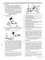 3
3
-
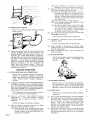 4
4
-
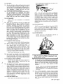 5
5
-
 6
6
-
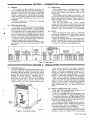 7
7
-
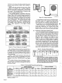 8
8
-
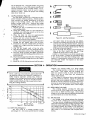 9
9
-
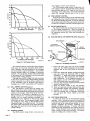 10
10
-
 11
11
-
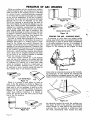 12
12
-
 13
13
-
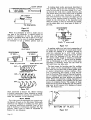 14
14
-
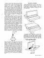 15
15
-
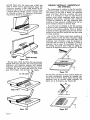 16
16
-
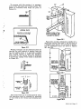 17
17
-
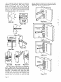 18
18
-
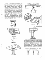 19
19
-
 20
20
-
 21
21
-
 22
22
-
 23
23
-
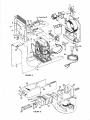 24
24


Miller M-180 Owner's manual
- Category
- Welding System
- Type
- Owner's manual
Ask a question and I''ll find the answer in the document
Finding information in a document is now easier with AI
Related papers
-
Miller 72-612483 Owner's manual
-
-
-
-
-
-
-
-
-
Other documents
-
Graintex AD2539 Operating instructions
-
Ideal 454® Blue Operating instructions
-
 Trek7 rbuv16 User manual
-
-
Buchanan 30-340P Installation guide
-
Miller Electric SWINGER 180 Installation, Operation & Maintenance Manual
-
-
ESAB Heliarc 250ts AC/DC Square Wave Power Sources Troubleshooting instruction
-
-
