Page is loading ...

July 7, 2003 Manual No. 0-2782
Operating Manual
Plasma Cutting
Power Supply
CE PAKMaster
©
75 XL
TM
Plus
A-02464

Plasma Cutting Power Supply
CE Pak Master
®
75XL
TM
Plus
Service Manual Number 0-2782
Published by:
Thermal Dynamics Corporation
82 Benning Street
West Lebanon, New Hampshire, USA 03784
(603) 298-5711
www.thermal-dynamics.com
Copyright 1999 by
Thermal Dynamics Corporation
All rights reserved.
Reproduction of this work, in whole or in part, without written per-
mission of the publisher is prohibited.
The publisher does not assume and hereby disclaims any liability to
any party for any loss or damage caused by any error or omission in
this Manual, whether such error results from negligence, accident, or
any other cause.
Printed in the United States of America
Publication Date: July 7, 2003
Record the following information for Warranty purposes:
Where Purchased:____________________________________
Purchase Date:_______________________________________
Power Supply Serial #:_______________________________
Torch Serial #:____________________________________
WARNINGS
Read and understand this entire Manual and your employer’s safety practices before installing, oper-
ating, or servicing the equipment.
While the information contained in this Manual represents the Manufacturer's best judgement, the
Manufacturer assumes no liability for its use.

TABLE OF CONTENTS
SECTION 1:
GENERAL INFORMATION ............................................................................................... 1-1
1.01 Notes, Cautions and Warnings ..................................................................... 1-1
1.02 Important Safety Precautions ....................................................................... 1-1
1.03 Publications.................................................................................................. 1-2
1.04 Note, Attention et Avertissement .................................................................. 1-3
1.05 Precautions De Securite Importantes........................................................... 1-3
1.06 Documents De Reference ............................................................................ 1-5
1.07 Declaration of Conformity ............................................................................. 1-7
1.08 Statement of Warranty.................................................................................. 1-8
SECTION 2:
INTRODUCTION .............................................................................................................. 2-1
2.01 Scope of Manual .......................................................................................... 2-1
2.02 General Description of System..................................................................... 2-1
2.03 Specifications/Design Features .................................................................... 2-1
2.04 Power Supply Options and Accessories....................................................... 2-2
SECTION 3:
INSTALLATION ................................................................................................................. 3-1
3.01 Introduction .................................................................................................. 3-1
3.02 Site Selection ............................................................................................... 3-1
3.03 Unpacking .................................................................................................... 3-1
3.04 Lifting Options .............................................................................................. 3-1
3.05 Input Power Cable Connections ................................................................... 3-2
3.06 Gas Connections ......................................................................................... 3-2
3.07 Connecting Torch Leads............................................................................... 3-4
3.08 Ground Connections For Mechanized Applications ...................................... 3-9
3.09 Tip Saver/Drag Sensing Circuit .................................................................. 3-11
SECTION 4:
OPERATION ..................................................................................................................... 4-1
4.01 Introduction .................................................................................................. 4-1
4.02 Operating Controls ....................................................................................... 4-1
4.03 Sequence of Operation ................................................................................ 4-3
4.04 Preparations for Operating ........................................................................... 4-5
4.05 Cut Quality ................................................................................................... 4-6

TABLE OF CONTENTS (continued)
SECTION 5:
SERVICE .......................................................................................................................... 5-1
5.01 Introduction .................................................................................................. 5-1
5.02 General Maintenance ................................................................................... 5-1
5.03 Common Operating Problems ...................................................................... 5-3
5.04 Troubleshooting Guide ................................................................................. 5-4
5.05 Power Supply Parts Replacement ................................................................ 5-6
SECTION 6:
PARTS LISTS.................................................................................................................... 6-1
6.01 Introduction .................................................................................................. 6-1
6.02 Ordering Information .................................................................................... 6-1
6.03 Complete Power Supply Replacement ......................................................... 6-2
6.04 Replacement Parts...................................................................................... 6-2
6.05 Options and Accessories ............................................................................. 6-2
APPENDIX 1: INPUT WIRING REQUIREMENTS ....................................................................A-1
APPENDIX 2: SEQUENCE OF OPERATION w(BLOCK DIAGRAM).......................................A-2
APPENDIX 3: MAINTENANCE SCHEDULE ............................................................................A-3
APPENDIX 4: DATA TAG INFORMATION .................................................................................A-4
APPENDIX 5: SYSTEM SCHEMATIC.......................................................................................A-6

Date: November 15, 2001 1-1 GENERAL INFORMATION
SECTION 1:
GENERAL INFORMATION
1.01 Notes, Cautions and Warnings
Throughout this manual, notes, cautions, and warnings
are used to highlight important information. These high-
lights are categorized as follows:
NOTE
An operation, procedure, or background informa-
tion which requires additional emphasis or is help-
ful in efficient operation of the system.
CAUTION
A procedure which, if not properly followed, may
cause damage to the equipment.
WARNING
A procedure which, if not properly followed, may
cause injury to the operator or others in the oper-
ating area.
1.02 Important Safety Precautions
WARNINGS
OPERATION AND MAINTENANCE OF
PLASMA ARC EQUIPMENT CAN BE DAN-
GEROUS AND HAZARDOUS TO YOUR
HEALTH.
Plasma arc cutting produces intense electric and
magnetic emissions that may interfere with the
proper function of cardiac pacemakers, hearing
aids, or other electronic health equipment. Per-
sons who work near plasma arc cutting applica-
tions should consult their medical health profes-
sional and the manufacturer of the health
equipment to determine whether a hazard exists.
To prevent possible injury, read, understand and
follow all warnings, safety precautions and in-
structions before using the equipment. Call 1-603-
298-5711 or your local distributor if you have any
questions.
GASES AND FUMES
Gases and fumes produced during the plasma cutting
process can be dangerous and hazardous to your health.
• Keep all fumes and gases from the breathing area.
Keep your head out of the welding fume plume.
• Use an air-supplied respirator if ventilation is not
adequate to remove all fumes and gases.
• The kinds of fumes and gases from the plasma arc
depend on the kind of metal being used, coatings
on the metal, and the different processes. You must
be very careful when cutting or welding any met-
als which may contain one or more of the follow-
ing:
Antimony Chromium Mercury
Arsenic Cobalt Nickel
Barium Copper Selenium
Beryllium Lead Silver
Cadmium Manganese Vanadium
• Always read the Material Safety Data Sheets
(MSDS) that should be supplied with the material
you are using. These MSDSs will give you the in-
formation regarding the kind and amount of fumes
and gases that may be dangerous to your health.
• For information on how to test for fumes and gases
in your workplace, refer to item 1 in Subsection 1.03,
Publications in this manual.
• Use special equipment, such as water or down draft
cutting tables, to capture fumes and gases.
• Do not use the plasma torch in an area where com-
bustible or explosive gases or materials are located.
• Phosgene, a toxic gas, is generated from the vapors
of chlorinated solvents and cleansers. Remove all
sources of these vapors.
• This product, when used for welding or cutting,
produces fumes or gases which contain chemicals
known to the State of California to cause birth de-
fects and, in some cases, cancer. (California Health
& Safety Code Sec. 25249.5 et seq.)
ELECTRIC SHOCK
Electric Shock can injure or kill. The plasma arc process
uses and produces high voltage electrical energy. This
electric energy can cause severe or fatal shock to the op-
erator or others in the workplace.
• Never touch any parts that are electrically “live”
or “hot.”

GENERAL INFORMATION 1-2 Date: November 15, 2001
• Wear dry gloves and clothing. Insulate yourself
from the work piece or other parts of the welding
circuit.
• Repair or replace all worn or damaged parts.
• Extra care must be taken when the workplace is
moist or damp.
• Install and maintain equipment according to NEC
code, refer to item 9 in Subsection 1.03, Publica-
tions.
• Disconnect power source before performing any
service or repairs.
• Read and follow all the instructions in the Operat-
ing Manual.
FIRE AND EXPLOSION
Fire and explosion can be caused by hot slag, sparks, or
the plasma arc.
• Be sure there is no combustible or flammable ma-
terial in the workplace. Any material that cannot
be removed must be protected.
• Ventilate all flammable or explosive vapors from
the workplace.
• Do not cut or weld on containers that may have
held combustibles.
• Provide a fire watch when working in an area where
fire hazards may exist.
• Hydrogen gas may be formed and trapped under
aluminum workpieces when they are cut under-
water or while using a water table. DO NOT cut
aluminum alloys underwater or on a water table
unless the hydrogen gas can be eliminated or dis-
sipated. Trapped hydrogen gas that is ignited will
cause an explosion.
NOISE
Noise can cause permanent hearing loss. Plasma arc pro-
cesses can cause noise levels to exceed safe limits. You
must protect your ears from loud noise to prevent per-
manent loss of hearing.
• To protect your hearing from loud noise, wear pro-
tective ear plugs and/or ear muffs. Protect others
in the workplace.
• Noise levels should be measured to be sure the deci-
bels (sound) do not exceed safe levels.
• For information on how to test for noise, see item 1
in Subsection 1.03, Publications, in this manual.
PLASMA ARC RAYS
Plasma Arc Rays can injure your eyes and burn your skin.
The plasma arc process produces very bright ultra violet
and infra red light. These arc rays will damage your
eyes and burn your skin if you are not properly protected.
• To protect your eyes, always wear a welding hel-
met or shield. Also always wear safety glasses with
side shields, goggles or other protective eye wear.
• Wear welding gloves and suitable clothing to pro-
tect your skin from the arc rays and sparks.
• Keep helmet and safety glasses in good condition.
Replace lenses when cracked, chipped or dirty.
• Protect others in the work area from the arc rays.
Use protective booths, screens or shields.
• Use the shade of lens as suggested in the following
per ANSI/ASC Z49.1:
Minimum Protective Suggested
Arc Current Shade No. Shade No.
Less Than 300* 8 9
300 - 400* 9 12
400 - 800* 10 14
* These values apply where the actual arc is clearly
seen. Experience has shown that lighter filters
may be used when the arc is hidden by the work-
piece.
1.03 Publications
Refer to the following standards or their latest revisions
for more information:
1. OSHA, SAFETY AND HEALTH STANDARDS, 29CFR
1910, obtainable from the Superintendent of Docu-
ments, U.S. Government Printing Office, Washington,
D.C. 20402
2. ANSI Standard Z49.1, SAFETY IN WELDING AND
CUTTING, obtainable from the American Welding So-
ciety, 550 N.W. LeJeune Rd, Miami, FL 33126
3. NIOSH, SAFETY AND HEALTH IN ARC WELDING
AND GAS WELDING AND CUTTING, obtainable
from the Superintendent of Documents, U.S. Govern-
ment Printing Office, Washington, D.C. 20402
4. ANSI Standard Z87.1, SAFE PRACTICES FOR OCCU-
PATION AND EDUCATIONAL EYE AND FACE PRO-
TECTION, obtainable from American National Stan-
dards Institute, 1430 Broadway, New York, NY 10018
5. ANSI Standard Z41.1, STANDARD FOR MEN’S
SAFETY-TOE FOOTWEAR, obtainable from the Ameri-
can National Standards Institute, 1430 Broadway, New
York, NY 10018

Date: November 15, 2001 1-3 GENERAL INFORMATION
6. ANSI Standard Z49.2, FIRE PREVENTION IN THE USE
OF CUTTING AND WELDING PROCESSES, obtain-
able from American National Standards Institute, 1430
Broadway, New York, NY 10018
7. AWS Standard A6.0, WELDING AND CUTTING CON-
TAINERS WHICH HAVE HELD COMBUSTIBLES, ob-
tainable from American Welding Society, 550 N.W.
LeJeune Rd, Miami, FL 33126
8. NFPA Standard 51, OXYGEN-FUEL GAS SYSTEMS
FOR WELDING, CUTTING AND ALLIED PRO-
CESSES, obtainable from the National Fire Protection
Association, Batterymarch Park, Quincy, MA 02269
9. NFPA Standard 70, NATIONAL ELECTRICAL CODE,
obtainable from the National Fire Protection Associa-
tion, Batterymarch Park, Quincy, MA 02269
10. NFPA Standard 51B, CUTTING AND WELDING PRO-
CESSES, obtainable from the National Fire Protection
Association, Batterymarch Park, Quincy, MA 02269
11. CGA Pamphlet P-1, SAFE HANDLING OF COM-
PRESSED GASES IN CYLINDERS, obtainable from the
Compressed Gas Association, 1235 Jefferson Davis
Highway, Suite 501, Arlington, VA 22202
12. CSA Standard W117.2, CODE FOR SAFETY IN WELD-
ING AND CUTTING, obtainable from the Canadian
Standards Association, Standards Sales, 178 Rexdale
Boulevard, Rexdale, Ontario, Canada M9W 1R3
13. NWSA booklet, WELDING SAFETY BIBLIOGRAPHY
obtainable from the National Welding Supply Associa-
tion, 1900 Arch Street, Philadelphia, PA 19103
14. American Welding Society Standard AWSF4.1, RECOM-
MENDED SAFE PRACTICES FOR THE PREPARA-
TION FOR WELDING AND CUTTING OF CONTAIN-
ERS AND PIPING THAT HAVE HELD HAZARDOUS
SUBSTANCES, obtainable from the American Welding
Society, 550 N.W. LeJeune Rd, Miami, FL 33126
15. ANSI Standard Z88.2, PRACTICE FOR RESPIRATORY
PROTECTION, obtainable from American National
Standards Institute, 1430 Broadway, New York, NY
10018
1.04 Note, Attention et
Avertissement
Dans ce manuel, les mots “note,” “attention,” et
“avertissement” sont utilisés pour mettre en relief des
informations à caractère important. Ces mises en relief
sont classifiées comme suit :
NOTE
Toute opération, procédure ou renseignement
général sur lequel il importe d’insister davantage
ou qui contribue à l’efficacité de fonctionnement
du système.
ATTENTION
Toute procédure pouvant résulter
l’endommagement du matériel en cas de non-
respect de la procédure en question.
AVERTISSEMENT
Toute procédure pouvant provoquer des blessures
de l’opérateur ou des autres personnes se trouvant
dans la zone de travail en cas de non-respect de la
procédure en question.
1.05 Precautions De Securite
Importantes
AVERTISSEMENTS
L’OPÉRATION ET LA MAINTENANCE DU
MATÉRIEL DE SOUDAGE À L’ARC AU JET
DE PLASMA PEUVENT PRÉSENTER DES
RISQUES ET DES DANGERS DE SANTÉ.
Coupant à l’arc au jet de plasma produit de l’énergie
électrique haute tension et des émissions
magnétique qui peuvent interférer la fonction
propre d’un “pacemaker” cardiaque, les appareils
auditif, ou autre matériel de santé electronique.
Ceux qui travail près d’une application à l’arc au
jet de plasma devrait consulter leur membre
professionel de médication et le manufacturier de
matériel de santé pour déterminer s’il existe des
risques de santé.
Il faut communiquer aux opérateurs et au person-
nel TOUS les dangers possibles. Afin d’éviter les
blessures possibles, lisez, comprenez et suivez tous
les avertissements, toutes les précautions de sécurité
et toutes les consignes avant d’utiliser le matériel.
Composez le + 603-298-5711 ou votre distributeur
local si vous avez des questions.
FUMÉE et GAZ
La fumée et les gaz produits par le procédé de jet de
plasma peuvent présenter des risques et des dangers de
santé.

GENERAL INFORMATION 1-6 Date: November 15, 2001
9. Norme 70 de la NFPA, CODE ELECTRIQUE NA-
TIONAL, disponible auprès de la National Fire Pro-
tection Association, Batterymarch Park, Quincy, MA
02269
10. Norme 51B de la NFPA, LES PROCÉDÉS DE
COUPE ET DE SOUDAGE, disponible auprès de la
National Fire Protection Association, Batterymarch
Park, Quincy, MA 02269
11. Brochure GCA P-1, LA MANIPULATION SANS
RISQUE DES GAZ COMPRIMÉS EN CYLINDRES,
disponible auprès de l’Association des Gaz
Comprimés (Compressed Gas Association), 1235
Jefferson Davis Highway, Suite 501, Arlington, VA
22202
12. Norme CSA W117.2, CODE DE SÉCURITÉ POUR
LE SOUDAGE ET LA COUPE, disponible auprès
de l’Association des Normes Canadiennes, Stan-
dards Sales, 178 Rexdale Boulevard, Rexdale,
Ontario, Canada, M9W 1R3
13. Livret NWSA, BIBLIOGRAPHIE SUR LA
SÉCURITÉ DU SOUDAGE, disponible auprès de
l’Association Nationale de Fournitures de Soudage
(National Welding Supply Association), 1900 Arch
Street, Philadelphia, PA 19103
14. Norme AWSF4.1 de l’Association Américaine de
Soudage, RECOMMANDATIONS DE PRATIQUES
SURES POUR LA PRÉPARATION À LA COUPE ET
AU SOUDAGE DE CONTENEURS ET TUYAUX
AYANT RENFERMÉ DES PRODUITS
DANGEREUX , disponible auprès de la American
Welding Society, 550 N.W. LeJeune Rd., Miami, FL
33126
15. Norme ANSI Z88.2, PRATIQUES DE PROTECTION
RESPIRATOIRE, disponible auprès de l’American
National Standards Institute, 1430 Broadway, New
York, NY 10018

Date: November 15, 2001 1-7 GENERAL INFORMATION
1.07 Declaration of Conformity
Manufacturer: Thermal Dynamics Corporation
Address: 82 Benning Street
West Lebanon, New Hampshire 03784
USA
The equipment described in this manual conforms to all applicable aspects and regulations of the ‘Low Voltage Directive’
(European Council Directive 73/23/EEC as amended by Council Directive 93/68/EEC) and to the National legislation for
the enforcement of this Directive.
The equipment described in this manual conforms to all applicable aspects and regulations of the "EMC Directive" (Euro-
pean Council Directive 89/336/EEC) and to the National legislation for the enforcement of this Directive.
Serial numbers are unique with each individual piece of equipment and details description, parts used to manufacture a unit
and date of manufacture.
National Standard and Technical Specifications
The product is designed and manufactured to a number of standards and technical requirements. Among them are:
* CSA (Canadian Standards Association) standard C22.2 number 60 for Arc welding equipment.
* UL (Underwriters Laboratory) rating 94VO flammability testing for all printed-circuit boards used.
* CENELEC EN50199 EMC Product Standard for Arc Welding Equipment.
* ISO/IEC 60974-1 (BS 638-PT10) (EN 60 974-1) (EN50192) (EN50078) applicable to plasma cutting equipment and associ-
ated accessories.
* For environments with increased hazard of electrical shock, Power Supplies bearing the
S
mark conform to EN50192
when used in conjunction with hand torches with exposed cutting tips, if equipped with properly installed standoff guides.
* Extensive product design verification is conducted at the manufacturing facility as part of the routine design and manufac-
turing process. This is to ensure the product is safe, when used according to instructions in this manual and related
industry standards, and performs as specified. Rigorous testing is incorporated into the manufacturing process to ensure
the manufactured product meets or exceeds all design specifications.
Thermal Dynamics has been manufacturing products for more than 30 years, and will continue to achieve excellence in our
area of manufacture.
Manufacturers responsible representative: Giorgio Bassi
Managing Director
Thermal Dynamics Europe
Via rio Fabbiani 8A
40067 Rastignano (BO)
Italy

GENERAL INFORMATION 1-8 Date: November 15, 2001
1.08 Statement of Warranty
LIMITED WARRANTY: Thermal Dynamics
®
Corporation (hereinafter “Thermal”) warrants that its products will be free of defects in
workmanship or material. Should any failure to conform to this warranty appear within the time period applicable to the Thermal
products as stated below, Thermal shall, upon notification thereof and substantiation that the product has been stored, installed, operated,
and maintained in accordance with Thermal’s specifications, instructions, recommendations and recognized standard industry practice,
and not subject to misuse, repair, neglect, alteration, or accident, correct such defects by suitable repair or replacement, at Thermal’s sole
option, of any components or parts of the product determined by Thermal to be defective.
THIS WARRANTY IS EXCLUSIVE AND IS IN LIEU OF ANY WARRANTY OF MERCHANTABILITY OR FITNESS FOR A
PARTICULAR PURPOSE.
LIMITATION OF LIABILITY: Thermal shall not under any circumstances be liable for special or consequential damages, such as, but
not limited to, damage or loss of purchased or replacement goods, or claims of customers of distributor (hereinafter “Purchaser”) for
service interruption. The remedies of the Purchaser set forth herein are exclusive and the liability of Thermal with respect to any
contract, or anything done in connection therewith such as the performance or breach thereof, or from the manufacture, sale, delivery,
resale, or use of any goods covered by or furnished by Thermal whether arising out of contract, negligence, strict tort, or under any
warranty, or otherwise, shall not, except as expressly provided herein, exceed the price of the goods upon which such liability is based.
THIS WARRANTY BECOMES INVALID IF REPLACEMENT PARTS OR ACCESSORIES ARE USED WHICH MAY IMPAIR THE
SAFETY OR PERFORMANCE OF ANY THERMAL PRODUCT.
THIS WARRANTY IS INVALID IF THE PRODUCT IS SOLD BY NON-AUTHORIZED PERSONS.
The limited warranty periods for Thermal products shall be as follows (with the exception of XL Plus Series, CutMaster Series , Cougar
and DRAG-GUN): A maximum of three (3) years from date of sale to an authorized distributor and a maximum of two (2) years from
date of sale by such distributor to the Purchaser, and with the further limitations on such two (2) year period (see chart below).
The limited warranty period for XL Plus Series and CutMaster Series shall be as follows: A maximum of four (4) years from date
of sale to an authorized distributor and a maximum of three (3) years from date of sale by such distributor to the Purchaser, and
with the further limitations on such three (3) year period (see chart below).
The limited warranty period for Cougar and DRAG-GUN shall be as follows: A maximum of two (2) years from date of sale to an
authorized distributor and a maximum of one (1) year from date of sale by such distributor to the Purchaser, and with the further
limitations on such two (2) year period (see chart below).
Parts
XL Plus & Parts Parts
PAK Units, Power Supplies CutMaster Series Cougar/Drag-Gun All Others Labor
Main Power Magnetics 3 Years 1 Year 2 Years 1 Year
Original Main Power Rectifier 3 Years 1 Year 2 Years 1 Year
Control PC Board 3 Years 1 Year 2 Years 1 Year
All Other Circuits And Components Including, 1 Year 1 Year 1 Year 1 Year
But Not Limited To, Starting Circuit,
Contactors, Relays, Solenoids, Pumps,
Power Switching Semi-Conductors
Consoles, Control Equipment, Heat 1 Year 1 Year 1 Year
Exchanges, And Accessory Equipment
Torch And Leads
Maximizer 300 Torch 1 Year 1 Year
SureLok Torches 1 Year 1 Year 1 Year
All Other Torches 180 Days 180 Days 180 Days 180 Days
Repair/Replacement Parts 90 Days 90 Days 90 Days None
Warranty repairs or replacement claims under this limited warranty must be submitted by an authorized Thermal Dynamics® repair
facility within thirty (30) days of the repair. No transportation costs of any kind will be paid under this warranty. Transportation charges
to send products to an authorized warranty repair facility shall be the responsibility of the customer. All returned goods shall be at the
customer’s risk and expense. This warranty supersedes all previous Thermal warranties.
Effective: November 15, 2001

Manual 0-2782 2-1 INTRODUCTION
SECTION 2:
INTRODUCTION
2.01 Scope of Manual
This manual contains descriptions, operating instructions
and basic maintenance procedures for the PAK Master
®
75XL PLUS Air Plasma Cutting Power Supply (CE). Ser-
vice of this equipment is restricted to properly trained
personnel; unqualified personnel are strictly cautioned
against attempting repairs or adjustments not covered in
this manual, at the risk of voiding the Warranty.
Read this manual thoroughly. A complete understand-
ing of the characteristics and capabilities of this equip-
ment will assure the dependable operation for which it
was designed.
2.02 General Description of System
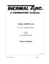
The 75XL PLUS (CE) System includes a power supply,
torch & leads and work cable & clamp, and input power
cable.
The Power Supply provides 60 amp maximum output
and includes all control circuitry, electrical and gas in-
puts and outputs, pilot circuitry, torch leads receptacle,
work cable with clamp, and input power cable.
The power supply can be ordered in various configura-
tions with various options factory installed. Refer to Sec-
tion 2.04 for list of power supply options and accesso-
ries.
A-02462
Torch and Leads
Work Cable and Clamp
XL PLUS Power Supply
Pak Master 75XL PLUS (CE) System
The system provides a maximum 1 inch (25.4 mm) cut
capacity. Torch heads are available in various configura-
tions. Torch leads are available in various lengths with
fittings for simple installation. Spare Parts Kits are avail-
able for the torches which provide an assortment of re-
placement torch parts.
2.03 Specifications/Design Features
A. Power Supply Technical Specifications
The following specifications apply to the Power Supply
only:
1. Front Panel Controls
ON/OFF Switch, RUN/SET/LATCH Switch and
Output Current Control
2. Front Panel Indicators
AC , TEMP , GAS , DC
3. Rear Panel
Input Power Cable, Gas Connection, Gas Regulator/
Filter Assembly
4. Input Power
380/415 VAC (±10%), 50/60 Hz, Three-Phase
Supplied with a 10 ft. (3.1 m) 4-Conductor Input
Power Cable with filtering beads.
5. Output Power
Continuously variable from 15 to 60 Amps maximum
6. Duty Cycle (see NOTE)
NOTE
The duty cycle will be reduced if the primary in-
put voltage (AC) is low or the DC voltage is higher
than shown in the chart.
Ambient
Tem
p
erature
104° F
(40° C)
104° F
(40° C)
Duty Cycle
65% 100%
Current
60 Amps 50 Amps
DC Voltage
104 vdc 104 vdc
Power Supply Duty Cycle
7. Cut Capacity (Mild Steel)
3/4 inch (19.1 mm); 1 inch (25.4 mm) severance

INTRODUCTION 2-2 Manual 0-2782
8. Pilot Circuitry
Capacitive Discharge (CD), Pulsed DC
9. Weight
71 lbs (32 kg) withwork lead, input power cable
78 lbs (35.4 kg) withwork lead, torch & lead, input power
cable
10. Overall Dimensions
19" (482 mm) High x 13" (330 mm) Wide x 24.8" (630
mm) Long
Overall dimensions are with Handle, Lead Wrap
Bracket, and Gas Regulator/Filter Assembly installed.
B. Gas Regulator/Filter Assembly
Specifications
The following specifications apply to the Gas Regulator/
Filter Assembly only:
1. Gas regulator maximum gauge pressure
160 psi (11 bar)
2. Maximum input gas pressure
125 psi (8.6 bar)
3. Filter
Coalescent type filter
2.04 Power Supply Options and
Accessories
The following accessories are available for this power
supply. Refer to Section 6, Parts Lists, for part numbers
and ordering information
A. Single Stage Air Line Filter Kit
A Single Stage In-Line Air Filter for use with com-
pressed air shop systems. Filters moisture and par-
ticulate matter from the air stream to at least 0.85 mi-
crons.
B. Two Stage Air Line Filter
A Two Stage In-Line Air Filter for use on compressed
air shop systems. Filters moisture and particulate mat-
ter from the air stream to at least 5.0 microns.
C. High Pressure Regulators
High pressure regulators are available for air and ni-
trogen. The regulators are used to set the proper pres-
sure for the type gas being used.
NOTE
Regulators should not be installed with options A
or B above.
D. Multi-Purpose Cart
Rugged steel cart on easy-rolling rear wheels and
front-mounted swivel casters. Provides maximum
mobility for the power supply and can also serve as a
display cart. Top shelf is 12 " (305 mm) x 20 (508 mm).
Steel handle is 30" (762 mm) high.
E. Computer Control Cable (CNC)
NOTE
This accessory can be used only with the PCM-60
Torches.
The interface cable is available in two lengths, 25 ft
(7.6 m) and 50 ft (15.2 m). The cable is used to inter-
face the power supply with an auxiliary control de-
vice to provide OK-To-Move and ON/OFF signals.
F. Remote Hand Pendant Control
The remote hand pendant control is available with a
20 ft. (6.1 m) cable. An extension cable of 25 ft. (7.6 m)
can be added to the standard hand pendant control to
produce a total length of 50 ft. (15.2 m).
G. Cutting Guide Kit
Easy add-on attachments to allow for straight line,
circle, or bevel cutting.
H. Standoff Cutting Guide
Simple, push-on guide attachment to allow for torch
dragging without risk of touching tip.

Manual 0-2782 3-1 INSTALLATION
SECTION 3:
INSTALLATION
3.01 Introduction
NOTE
Depending on how the system was ordered, some
Power Supply Options may already be installed.
If option(s) have been factory installed some of the
instructions may not apply. It is recommended that
all subsections be read for general information.
This section describes installation of the Power Supply
and connecting the Torch.
These instructions apply to the Power Supply only; instal-
lation procedures for the Torch, Options, and Accessories
are given in Manuals specifically provided for those units.
The complete installation consists of:
1. Site selection
2. Unpacking
3. Connections to Power Supply
a. Input power
b. Gas
c. Work cable
d. Torch Leads
4. Grounding
5. Operator training
3.02 Site Selection
Select a clean, dry location with good ventilation and ad-
equate working space around all components.
NOTE
Review Important Safety Precautions (Section 1)
to be sure that the selected location meets all safety
requirements.
The power supply is fan cooled by air flow through the
front panel to the rear panel. Air flow must not be ob-
structed. Provide at least 2 feet (0.61 m) in the rear and at
least 6 inches (150 mm) on each side for clearance . Pro-
vide sufficient clearance in front of the unit to allow ac-
cess to the front panel controls (minimum 6 inches or 150
mm).
CAUTION
Operation without proper air flow will inhibit
proper cooling and reduce duty cycle.
3.03 Unpacking
Each component of the system is packaged and protected
with a carton and packing material to prevent damage
during shipping.
l. Unpack each item and remove any packing material.
NOTE
The Cutting Spare Parts Kit is shipped in the Torch
Leads Storage Area on the side of the Power Sup-
ply.
2. Locate the packing list(s) and use the list to identify
and account for each item.
3. Inspect each item for possible shipping damage. If
damage is evident, contact your distributor and/or
shipping company before proceeding with system in-
stallation.
3.04 Lifting Options
WARNINGS
Do not touch live electrical parts.
Disconnect input power conductors from de-ener-
gized supply line before moving unit.
FALLING EQUIPMENT can cause serious per-
sonal injury and equipment damage.
This unit is equipped with one handle mounted onto the
top of the enclosure for hand carrying purposes.
• Lift unit with the handle on top of the enclosure.
• Only persons of adequate physical strength should
lift the unit.
• Use hand cart, optional Cart, or similar device of
adequate capacity.
• If using a fork lift vehicle, place and secure unit on
a proper skid before transporting.
• This unit has a handle mounted on top of the enclo-
sure for hand lifting only. Be sure unit is lifted and
transported safely and securely.
WARNING
HANDLE is not for mechanical lifting.

INSTALLATION 3-2 Manual 0-2782
3.05 Input Power Cable Connections
The 75XL PLUS Power Supply operates on three phase,
380-415 VAC ± 10% 50/60 Hz input.
CAUTION
The primary power source, power cable, and plug
must all conform to local electric code and the rec-
ommended circuit protection and wiring require-
ments (refer to Appendix 1).
The Power Supply is supplied with a three-phase, four
conductor, input EMC power Cable attached. Connect
the supplied input EMC power cable to the customer's
power source per the following procedure:
NOTE
The input power cable must not be modified in any
way as filtering beads are installed onthe cable.
1. Strip back the outer covering approximately 3
inches (76 mm) to expose the individual wires at
the free end of the cable.
2. Cut back the insulation on the individual wires
approximately 1/8 - 3/16 inch (3-5 mm).
3. Connect the ends of the individual wires a cus-
tomer supplied plug or main disconnect per the
following:
NOTE
All the input cable wires must be connected for
three-phase operation.
• Blue wire to Line 2 (Live)
• Black wire to Line 3 (Live), refer to Note above
• Brown wire to Line 1 (Live)
• Green/Yellow wire to Ground (Earth)
3.06 Gas Connections
A. Gas Requirements
WARNING
This unit not to be used with oxygen (O
2
).
Gases: Compressed Air or Nitrogen (N2) Only
Pressure: 60 - 75 psi (4.1 - 5.2 bar)
CAUTION
Maximum input gas pressure must not exceed 125
psi (8.6 bar)
Flow: Cutting - 300 scfh standard cubic feet/hour(142 lpm)
Gouging - 300 scfh (142 lpm)
B. Checking Air Quality
To test the quality of air, place the RUN/SET/LATCH
switch to SET position, place a welding filter lens in front
of the torch and turn on the gas. Any oil or moisture in
the air will be visible on the lens. Do not initiate an arc!
CAUTION
The air supply must be free of moisture, and other
contaminants. Excessive moisture may cause
double-arcing, rapid tip wear, or even complete
torch failure. Contaminants may cause poor cut-
ting performance and rapid electrode wear.
C. Gas Connections
The gas supply is connected to the Pressure Regulator/
Filter Assembly installed on the rear of the unit. The con-
nection is the same for compressed air or high pressure
gas cylinders.
Connect the gas supply as illustrated. Typical fittings are
shown as examples. Other fittings may be used.
1. If an optional air line filter is to be installed, refer to
subsection D.
NOTE
Filtering is required when using air from a com-
pressor to ensure that moisture and debris from the
supply hose does not enter the torch. It is recom-
mended to order the optional

Manual 0-2782 3-3 INSTALLATION
3
Regulator/Filter
Assembly
1/4 NPT to #4 (6 mm) Hose
Fitting
#4 (6 mm) Gas
Supply Hose
Hose Clamp
A-01149
Figure 3-1 Gas Connection To Regulator/Filter
Assembly
D. Optional Air Line Filter Installation
Filtering is required when using air from a compressor to
insure that moisture and debris from the supply hose does
not enter the torch. Although the Regulator does have its
own filter, it is recommended the optional Single-Stage
Filter or optional Two Stage Air Line Filter be installed
for improved filtering. Gas connections to optional fil-
ters are shown in Figures 3-2 and 3-3.
Single-Stage Air Filter Kit or Two Stage Filter Kit As-
sembly
A-02607
1/4 NPT to #4 (6mm)
Hose Fitting
Air Line Filter
Assembly
#4 (6mm) Gas
Supply Hose
Hose Clamp
Figure 3-2 Gas Connection to Optional Single-Stage
Air Filter Assembly
Two Stage Filter
Assembly
1/4 NPT to
#4 (6mm) Hose
Fitting
#4 (6mm) Gas
Supply Hose
Hose Clamp
A-01150
Figure 3-3 Gas Connection To Optional Two Stage
Filter Assembly

INSTALLATION 3-4 Manual 0-2782
E. Using High Pressure Gas Cylinders
1. Refer to the following when using high pressure gas
cylinders as the gas supply:
CAUTION
Pressure should be set at 100 psi (6.9 bar) at the
high pressure gas cylinder regulator.
a. Refer to the manufacturer’s specifications for in-
stallation and maintenance procedures for high
pressure gas regulators.
b. Examine the cylinder valves to be sure they are
clean and free of oil, grease or any foreign mate-
rial. Momentarily open each cylinder valve to blow
out any dust which may be present.
c. The cylinder must be equipped with an adjustable
high-pressure regulator capable of outlet pressures
up to 100 psi (6.9 bar) maximum and flows of up
to 300 scfh (141.5 lpm).
NOTE
Supply hose must be at least #4 hose (1/4 in or 6
mm I.D.).
3.07 Connecting Torch Leads
CAUTION
This system is designed for use with the PCH/M-
102, SL60, or SL100 torches only. Do not connect
any other torch to this power supply.
The instructions for connecting the Torch Leads to the
Power Supply are different depending on the type of
leads. This sub-section covers connecting the Torch for
the following applications:
A. Hand Systems
B. Machine Systems (Unshielded Leads)
C. Machine Systems (Shielded Leads)
The Torch Leads must be properly installed to the Power
Supply for proper operation. If the torch leads were not
factory-installed, make all torch connections to the Torch
Bulkhead Panel for the desired application.
NOTE
Equipment ordered as a system will have the Torch
factory connected to the Power Supply.
A. Hand Systems
WARNING
Disconnect primary power at the source before as-
sembling or disassembling the power supply, torch
parts, or torch and leads assemblies.
1. Turn the screw latch securing the front access panel
to the power supply front panel.
Access
Panel
Screw
Latch
A-02467
Figure 3-4 Front Access Panel
2. Lift the access panel to gain access to the torch
bulkhead panel.
3. Remove the securing nut from the strain relief sup-
plied on the end of the Torch Leads.
NOTE
The leads may include a pair of wires connected
together and covered with an insulating sleeve.
These wires must remain connected and insulated.

Manual 0-2782 3-5 INSTALLATION
Retaining Nut
Strain Relief
Torch Leads
Assembly
A-02836
Figure 3-5a Torch Strain Relief Nut (Leads with
Two Control Wires)
Strain Relief
Nut
Strain Relief
Torch Leads
Assembly
A-03607
Negative /
Plasma Lead
Pilot Lead
Figure 3-5b Torch Strain Relief Nut (Leads with
Four Control Wires)
4. Feed the torch lead ends and the Strain Relief into
the hole in the unit.
5. Secure the Strain Relief with the retaining nut re-
moved earlier.
6. Connect the torch Negative/Plasma Lead to the
bulkhead connection inside the Power Supply.
Adapter
(Supplied With
Power Supply)
Pilot Lead
Torch Lead
Assembly
Negative/Plasma
Lead
Adapter
Connector
Pilot Lead Stud
Negative/Plasma Lead
Connection
A-02825
Control (PIP) Circuit
Connectors
Figure 3-6a Torch Lead Connections (Leads with
Two Control Wires)
Pilot Lead
Torch Lead
Assembly
Negative/Plasma
Lead
Adapter
Connector
Pilot Lead Stud
Negative/Plasma
Lead Connection
A-03608
Note: Actual Bulkhead
configuration may
differ from that shown.
Adapter
Control Circuit
Connectors
Figure 3-6b Torch Lead Connections (Leads with
Four Control Wires)
7. Connect the Control Cables to the mating connec-
tors on the Adapter supplied on the Power Sup-
ply.

INSTALLATION 3-6 Manual 0-2782
8. Remove the top nut and washer from the Pilot
Stud.
9. Place the lug on the Pilot Control Wire onto the
stud and secure with the nut and washer removed
in the above Step.
10. Tighten the Strain Relief onto the Torch Leads.
11. Check the torch for proper parts assembly.
12. Close the access panel and turn the latching screw.
B. Machine Systems (PCM-62 Torch with
Unshielded Leads)
WARNING
Disconnect primary power at the source before as-
sembling or disassembling the power supply, torch
parts, or torch and leads assemblies.
1. Turn the screw latch securing the front access panel
to the power supply front panel.
2. Lift the access panel to gain access to the torch
bulkhead panel.
3. Remove the retaining nut from the Strain Relief.
Strain Relief
Nut
Strain Relief
Torch Leads
Assembly
A-02827
Figure 3-7 Strain Relief Nut Removal
4. The Adapter supplied with the Power Supply must
be installed per the following:
a. Inside the Power Supply Bulkhead area, route
the connector on the free end of the Adapter
through the Strain Relief Nut.
b. Continue routing the connector out the hole in
the front panel of the Power Supply.
c. Feed the end of the torch lead and the Strain
Relief into the hole in the unit while routing
the single black wire into the notch of the Strain
Relief.
d. Tighten the Strain Relief Nut to secure the
Strain Relief to the Power Supply.
Adapter
(Supplied With
Power Supply)
Pilot Lead
Torch Lead
Assembly
Negative/Plasma
Lead
Adapter Connector
Pilot Lead
Stud
Negative/Plasma
Lead Connection
A-02828
Control (PIP) Circuit
Connectors
Shield Connectors
(Not Used)
Remote
Cable
Connector
Figure 3-8 Torch Lead Connections
5. Connect the torch Negative/Plasma Lead to the
bulkhead connection inside the Power Supply.
6. Connect the Control (PIP) Circuit Connectors to
the mating connectors on the Adapter supplied on
the Power Supply (see Warning).
WARNING
The Adapter supplied with the Power Supply has
two additional Shield Connectors that are used for
Shielded Systems only. These two connectors are
not used and need to be taped out of the way to
prevent contacting the Negative/Plasma or Pilot
Leads.
7. Remove the top nut and washer from the Pilot
Stud.
8. Place the lug on the Pilot Control Wire onto the
stud and secure with the nut and washer removed
in the above Step.
9. Tighten the Strain Relief onto the Torch Leads.

Manual 0-2782 3-7 INSTALLATION
10. Check the torch for proper parts assembly.
11. Close the access panel and turn the latching screw.
C. Machine Systems (PCM-62 Torch with
Shielded Leads)
WARNING
Disconnect primary power at the source before as-
sembling or disassembling the power supply, torch
parts, or torch and leads assemblies.
1. Turn the screw latch securing the front access panel
to the power supply front panel.
2. Lift the access panel to gain access to the torch
bulkhead panel.
3. Remove the retaining nut from the Strain Relief.
Strain Relief
Nut
Strain Relief
Torch Leads
Assembly
A-02826
Figure 3-9 Strain Relief Nut Removal
4. The Adapter supplied with the Power Supply must
be installed per the following:
a. Inside the Power Supply Bulkhead area, route
the connector on the free end of the Adapter
through the Strain Relief Nut.
b. Continue routing the connector out the hole in
the front of the Power Supply.
c. Feed the end of the torch lead and the Strain
Relief into the hole in the unit while routing
the single black wire into the notch of the Strain
Relief.
d. Tighten the Strain Relief Nut to secure the
Strain Relief to the Power Supply.
Adapter
(Supplied With
Power Supply)
Pilot Lead
Torch Lead
Assembly
Negative/Plasma
Lead
Adapter Connector
Pilot Lead
Stud
Negative/Plasma
Lead Connection
A-02829
Control (PIP) Circuit
Connectors
Shield Connectors
Figure 3-10 Torch Lead Connections
5. Connect the torch Negative/Plasma Lead to the
bulkhead connection inside the Power Supply.
6. Connect the PIP and Shield Cables to the mating
connectors on the Adapter supplied on the Power
Supply.
7. Remove the top nut and washer from the Pilot
Stud.
8. Place the lug on the Pilot Control Wire onto the
stud and secure with the nut and washer removed
in the above Step.
9. Tighten the Strain Relief onto the Torch Leads.
10. Check the torch for proper parts assembly.
11. Close the access panel and turn the latching screw.

INSTALLATION 3-8 Manual 0-2782
D. Machine Systems (SL100 Torch)
Torches with O2B connectors connect directly to the
power supply bulkhead. Mechanized torch leads with
O2B connectors require a remote pendant adapter to ac-
cept a remote pendant.
WARNING
Disconnect primary power at the source before dis-
assembling the torch or torch leads.
1. Remove the Strain Relief Nut from the Strain Re-
lief.
Strain Relief
Nut
Strain Relief
Torch Leads
Assembly or ATC Adapter
A-03530
Remove Tie Wrap,
Remove Insulator,
Disconnect Wires
Strain Relief Nut Removal
2. The leads Assembly includes two wires joined with
mating connectors and covered with an insulat-
ing sleeve. Remove the tie wrap and insulating
sleeve. Disconnect the two joined wires.
3. Feed the end of the torch leads and the Strain Re-
lief into the hole in the unit.
4. Route the wire harness on the Remote Pendant
Adapter through the Strain Relief and Strain Re-
lief Nut. Tighten the Strain Relief Nut to secure
the Strain Relief to the Power Supply.
5. Connect the Negative / Plasma lead to the bulk-
head connection inside the power supply.
6. Connect the control circuit connectors on the Torch
Leads to the mating connectors on the Remote
Pendant Adapter and Power Supply Adapter (see
Warning).
WARNING
There are two additional connectors that are not
used and must be taped out of the way to prevent
contacting the Negative / Plasma or Pilot Leads.
7. Remove the top nut and washer from the Pilot Stud
on the power supply bulkhead.
8. Place the Torch Leads Pilot lead terminal on onto
the stud and secure with the nut and washer re-
moved in the above Step.
A-03675
Torch Lead
Assembly
Control Circuit
Connectors
Open
Open
Power Supply
Adapter
Pilot Lead
Negative/Plasma
Lead
Adapter
Connector
Pilot Lead Stud
Negative/Plasma
Lead Connection
Note: Actual Bulkhead
configuration may
differ from that shown.
Remote Pendant
Adapter Wire Harness
Bulkhead Connection - Unshielded Machine Torch
with O2B Fittings and Remote Pendant Adapter
9. Connect the Torch Leads connectors and the re-
mote pendant adapter connector to the power sup-
ply adapter as shown.
/