Potter INS-2500 User manual

Category
Air compressors
Type
User manual
Manual #5403680 - F
05/23
St. Louis, MO
800-325-3936
www.pottersignal.com
INS-2500
Nitrogen Generator
Installation, Operation, and
Instruction Manual
2
INS-2500 • 5403680 • REV F• 05/23
Potter Electric Signal Company, LLC
St. Louis, MO • (866) 956-0988
WARRANTY INFORMATION
GENERAL PROVISIONS & LIMITATIONS
Potter Electric Signal Company, LLC (the “Company”) warrants to each original purchaser (“Purchaser”) of its new products from the
Company or its Authorized Distributor that such products are, at the time of delivery to the Purchaser, made with good materials and
workmanship. No warranty is made with respect to:
1. Any product, which has been repaired or altered in such a way, in the Companies judgment, as to aect the product adversely.
2. Any product, which has, in the Companies judgment been subjected to negligence, accident, improper storage, improper installation
or application.
3. Any product, which has not been operated or maintained in accordance with the recommendations of the Company.
4. Components or accessories manufactured, warranted and serviced by others.
5. Any reconditioned or prior owned product.
Claims for items described in 4 above should be submitted directly to the manufacturer.
WARRANTY PERIOD
The Company’s obligation under this Warranty is limited to repair or, at its option, replacing during normal business hours at the designated
facility of the Company, any part that in its judgment proved not to be as warranted within the applicable Warranty Period as follows.
COMPONENTS
All non-consumable components are warranted for 12 months from the date of purchase. Consumable are not covered under warranty. The
unit must have been installed by either a factory authorized distributor or agent in accordance with the factory recommendations taking into
account all other local site conditions not originally noted to the factory. The unit must be operated and maintained in accordance with the
Factory recommendations and original design conditions. Failure to provide such proof of the above may void warranty.
LABOR TRANSPORTATION & INSPECTION
The Company will repair or replace any product or part thereof which in the Companies judgment is proved to be not as warranted. Labor
costs are not covered under warranty.
All costs of transportation of product, labor or parts claimed not to be as warranted and, of repaired or replaced parts to or from factory
shall be borne by purchaser. The Company may require the return of any part claimed not to be as warranted to one of its facilities as
designated by the Company, transportation prepaid by Purchaser, to establish a claim under this warranty.
Replacement parts provided under the terms of the warranty are warranted for the remainder of the Warranty Period of the product upon
which installed to the same extent as if such parts were original components.
DISCLAIMER
THE FOREGOING WARRANTY IS EXCLUSIVE AND IT IS EXPRESSLY AGREED THAT, EXCEPT AS TO TITLE, THE
COMPANY MAKES NO OTHER WARRANTIES, EXPRESSED OR IMPLIED OR STATUTORY, INCLUDING ANY IMPLIED
WARRANTY OR MERCHANTABILITY.
THE REMEDY PROVIDED UNDER THIS WARRANTY SHALL BE THE SOLE, EXCLUSIVE AND ONLY REMEDY AVAILABLE
TO THE PURCHASER AND IN NO CASE SHALL THE COMPANY BE SUBJECT TO ANY OTHER OBLIGATIONS OR
LIABILITIES. UNDER NO CIRCUMSTANCES SHALL THE COMPANY BE LIABLE FOR SPECIAL, INDIRECT, INCIDENTAL OR
CONSEQUENTIAL DAMAGES, EXPENSES, LOSSES OR DELAYS HOWSOEVER CAUSED.
No statement, representation, agreement, or understanding, oral or written, made by any agent, distributor, representative or employee of
the Company which is not contained in this Warranty will be binding upon the company unless made in writing and executed by an ocer
of the Company.
This warranty shall not be eective as to any claim which is not presented within 30 days after the date upon which the product is claimed
not to have been as warranted. Any action for breach of this warranty must be commenced within one year after the date upon which the
cause of action occurred.
Any adjustment made pursuant to this warranty shall not be construed as an admission by the Company that any product was not as
warranted.
PROMPT DISPOSITION
The Company will make a good faith eort for prompt correction or other adjustment with respect to any product, which proves to
be defective within the warranty period. Before returning any product, write or call the distributor, agent or authorized company from
which the product was purchased, describing defect and giving date and number of original invoice, as well as proof of Factory supplied
consumable and proof of scheduled maintenance. Title and risk of loss pass to buyer upon delivery to the common carrier.
PRODUCT SUITABILITY
Many States, Localities and Countries have codes and regulations governing sales, construction, installation, and/or use of products for
certain purposes, which may vary from those in neighboring areas. While Potter attempts to assure that its products comply with such
codes, it cannot guarantee compliance, and cannot be responsible for how the product is installed or used. Before purchase and use of a
product, please review the product application, and national and local codes and regulations, and be sure that the product, installation, and
use will comply with them.
3
INS-2500 • 5403680 • REV F • 05/23
Contents
Safety Guidelines ............................................................................................................................................................................................... 4
Important Notice to Users ........................................................................................................................................................................ 4
Unpacking ................................................................................................................................................................................................ 4
General Safety Information ......................................................................................................................................................................4
System Overview ............................................................................................................................................................................................... 6
Key Terms ................................................................................................................................................................................................ 6
IntelliGen Controller ..............................................................................................................................................................................6
INS-2500 Exterior View ....................................................................................................................................................................................7
INS-2500 Interior View .....................................................................................................................................................................................8
INS-2500 Nitrogen Tank View ..........................................................................................................................................................................9
INS-2500 Air Compressor View ........................................................................................................................................................................ 10
IntelliGen Display ...........................................................................................................................................................................................11
Installation of the Nitrogen Generator ...............................................................................................................................................................12
Wiring of the Nitrogen Generator ......................................................................................................................................................................16
Air Compressor (208V, 230V or 460V Three Phase) ..............................................................................................................................16
Compressor Sensor Wire ..........................................................................................................................................................................17
Air Tank Blow-Down Located on the Bottom of the Tank Mounted Air Compressor (120V) ...............................................................18
Nitrogen Cabinet (120V) .........................................................................................................................................................................18
Internet Connectivity, PLINK, and BMS (Optional) ............................................................................................................................... 19
Nitrogen Generator Operation ...........................................................................................................................................................................20
Nitrogen Functionality Test ..............................................................................................................................................................................22
Filling the Sprinkler System and Purging .......................................................................................................................................................... 23
Purging with IntelliPurge® Nitrogen Purge Valve (INS-PV) .............................................................................................................................24
Purging with Potter Nitrogen Purge Valve (NGP-SPV) ....................................................................................................................................25
IntelliView Dashboard Internet Connectivity ..................................................................................................................................................26
IntelliPurge® Wiring and Networking ................................................................................................................................................................ 27
Maintenance and Part Replacements .................................................................................................................................................................29
Standard Maintenance (Every 1,000 Compressor Operating Hours) ................................................................................................................30
Compressor Air Intake Filters ..................................................................................................................................................................31
Air Tank Blow-down Strainer ..................................................................................................................................................................32
Lubricated Air Compressor Oil ................................................................................................................................................................32
Filter Elements ......................................................................................................................................................................................... 33
Resetting Maintenance Alert and Checking for Leaks ............................................................................................................................35
Air Compressor Replacement ............................................................................................................................................................................ 35
Nitrogen Membrane Replacement .....................................................................................................................................................................36
Maintenance Alerts and Actions ........................................................................................................................................................................37
Trouble Alerts and Probable Causes ..................................................................................................................................................................38
Troubleshooting .................................................................................................................................................................................................40
Leak on Sprinkler System or Nitrogen Generator ...................................................................................................................................40
Nitrogen Flow Rate and Nitrogen Purity Test .........................................................................................................................................40
Normal Operating Parameters of the INS-2500 .................................................................................................................................................41
Nitrogen Generator Leak Detection System ...................................................................................................................................................... 42
To Change the Leak Rate Warning Set Point .............................................................................................................................................43
To Change Sprinkler System Size ..............................................................................................................................................................43
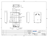
INS-2500 Cabinet Dimensional Drawings ........................................................................................................................................................44
INS-2500 Compressor Dimensional Drawings .................................................................................................................................................45
INS-2500 Air Tank Dimensional Drawings .......................................................................................................................................................46
INS-2500 Piping Instrumentation Diagram ....................................................................................................................................................... 47
Wiring Diagrams ................................................................................................................................................................................................48
INS-2500 200-208VAC Three Phase ....................................................................................................................................................... 48
INS-2500 230-240VAC Three Phase ....................................................................................................................................................... 49
INS-2500 460-480VAC Three Phase ....................................................................................................................................................... 50
Menu Trees.........................................................................................................................................................................................................51
Menu Tree 1 ............................................................................................................................................................................................. 51
Menu Tree 2 ............................................................................................................................................................................................. 52
Menu Tree 3 ............................................................................................................................................................................................. 53
Menu Tree 4 ............................................................................................................................................................................................. 54
Menu Tree 5 ............................................................................................................................................................................................. 55
Menu Tree 6 ............................................................................................................................................................................................. 56
Menu Tree 7 ............................................................................................................................................................................................. 57
4
INS-2500 • 5403680 • REV F• 05/23
This manual contains safety information that is important to know and understand. This
information is provided for the safety of installers, operators, and users of the Potter
Nitrogen Generator as well as equipment. To help recognize this information, observe the
following symbols.
Safety Guidelines
Danger indicates an imminently hazardous situation which, if not avoided, WILL result in death or serious injury.
Warning indicates a potentially hazardous situation which, if not avoided, COULD result in death or serious injury.
Caution indicates a potentially hazardous situation which, if not avoided, MAY result in minor or moderate injury
Notice indicates important information, that if not followed may cause damage to equipment or property.
CAUTION
DD
Important Notice to Users
The Installation, Operation, and Instruction Manual supplied with each unit must be read thoroughly and completely understood
before installation and operation of the Potter IntelliGen Nitrogen Generator. All appropriate safety standards for handling of
gases as determined by local or national laws and regulations should be followed at all times.
Unpacking
After unpacking unit, carefully inspect all parts and equipment for any damage that may have occurred during transit. Make sure
to tighten ttings, bolts, etc. before putting unit into service.
Do not operate if damage occurred during shipping, handling, or
use. Contact Potter immediately.
General Safety Information
Important: Read all of the safety information in this manual before operating this equipment. Use of the equipment in a manner
not specied within this manual may impair the protection provided by the generator and could result in an unplanned release of
pressure, which may cause serious injury or damage. Only competent personnel, who have been trained, qualied, and approved
by Potter Electric Signal Company should perform commissioning, servicing, and repair procedures.
When handling, installing, or operating this equipment, personnel must employ safe engineering practices and observe all related
local regulations, health, and safety procedures, and legal requirements for safety. Ensure that the equipment is depressurized and
electrically isolated, before carrying out any of the scheduled maintenance instructions specied in this manual.
5
INS-2500 • 5403680 • REV F • 05/23
The warnings in this manual cover most known potential hazards, but by denition cannot be all-inclusive. If the user employs an
operating procedure, item of equipment, or a method of working that is not specically recommended by Potter Electric Signal
Company, the user must ensure that the equipment will not be damaged or become hazardous to persons or property.
Nitrogen is not a poisonous gas. However, in a concentrated form, there is a risk of asphyxiation. The generator produces a ow
of nitrogen and oxygen enriched air which quickly disperses in the atmosphere. However, do not directly inhale the output gas
from the outlet pipe.
The generator is classied as non-hazardous for transportation purposes and as non-ammable for re regulations. This equipment
is for indoor use only. Do not operate outdoors.
Specic procedure must be developed for maintenance of the equipment on which the membrane separator is located. Appropriate
labels must be continuously displayed in all areas where personnel might be exposed to a nitrogen atmosphere under normal or
upset condition.
Do not attempt to disassemble the nitrogen membrane sepa-
rator. Equipment damage may occur and cause the system to
function incorrectly.
Operation of the nitrogen membrane separator above the
rated design pressure may be hazardous. Do not connect it
to compressed air sources that can exceed its maximum rated
pressure without installing appropriate pressure controls and
safety relief devices in the compressed air supply line.
6
INS-2500 • 5403680 • REV F• 05/23
System Overview
Key Terms
Potter IntelliGen Nitrogen Generators are specically designed to provide clean, dry, high purity nitrogen for use in re
protection sprinkler systems. The generator is a fully assembled package ready to be connected to a new or existing re sprinkler
system using a factory pre-engineered air compressor. These easy-to-use systems include all air ltration equipment and controls
required to keep the generator operating at peak eciency.
The Potter IntelliGen Nitrogen Series operates using membrane technology. The smaller oxygen and water vapor molecules
can pass through (permeate) the membrane quickly. The larger nitrogen molecules are less likely to diuse through the separator
tubes; therefore, they continue downstream to the separator outlet. The permeated molecules are discharged to the atmosphere
through a vent in the separator housing.
Bypass Mode – Most nitrogen generators cannot produce enough nitrogen to completely ll the sprinkler system in 30 minutes
required by NFPA 13. Therefore, they contain valves that allow the nitrogen membrane to be bypassed so the system can be lled
with compressed air. The valve setting that bypasses the nitrogen membrane is called Bypass Mode.
Nitrogen Generating ModeThe valve setting that allows the air to ow through the nitrogen membrane and create nitrogen is
called Nitrogen Generating Mode.
Purging – Purging is dened as the removal of oxygen from the sprinkler system via a purge valve. The purge valve allows some
gas to escape from the system which requires the nitrogen generator to supply nitrogen to maintain system pressure. This process
therefore increases the nitrogen concentration within the system piping over time.
IntelliGen Controller
The IntelliGen Nitrogen Generator Series is the only line of intelligent nitrogen generators for re sprinkler systems. At the heart
of the IntelliGen units, is the IntelliGen Controller. The IntelliGen Controller monitors every aspect of the nitrogen generator
to ensure the unit is performing optimally. The IntelliGen Controller monitors pressure, runtime, power, connectivity and
operational mode. Using this information and proprietary algorithms, the IntelliGen Controller can determine if the unit needs
to be in Bypass Mode or Nitrogen Generating Mode. No need to manually change ball valve congurations or worry if the unit
is producing nitrogen. Also, by monitoring the generator activity the controller can indicate the development of sprinkler system
leaks, user interaction, and even if maintenance to the generator is required. Combined with the IntelliPurge® Nitrogen Purge
Valve, the IntelliGen Nitrogen Generator is the only system that can truly monitor and protect a sprinkler system.
See Menu Tree Diagram on page 51 for more information on programming.
The INS-2500 has a Bypass Fill Capacity of 2,400 gallons at 40 psi and a Total System Capacity of 24,000 gallons
Part Number Model Description
1119647 INS-2500, 200-208VAC 3PH 60HZ IntelliGen Nitrogen System-2500, 200-208VAC Three Phase
1119648 INS-2500, 230-240VAC 3PH 60HZ IntelliGen Nitrogen System-2500, 230-240VAC Three Phase
1119649 INS-2500, 460-480VAC 3PH 60HZ IntelliGen Nitrogen System-2500, 460-480VAC Three Phase
7
INS-2500 • 5403680 • REV F • 05/23
INS-2500 Exterior Cabinet View
Fig. 1
12
3
4
5
6
7
1. Upper Cabinet Latches (Qty. 2)
2. IntelliGen Display
3. Control Power Only Switch
4. Compressor Sensor Wire Cord Grip
5. Locking Door Handle
6. Nitrogen Tank Connection (1/2" FNPT)
7. Air Tank Connection (1/2" FNPT)
8. 3/8" Drain Tube Connection (10 ft. Supplied)
8
8
INS-2500 • 5403680 • REV F• 05/23
INS-2500 Interior View
Fig. 2
1. Nitrogen Membrane (M01)
2. Flow Control Valve (FCV01)
3. Back Pressure Regulator (PRV02)
4. Instrument Air Solenoids
5. Membrane Outlet N2 Solenoid (XV02)
6. Owner Supplied Power Connection
7. IntelliGen Controller
8. Compressor Sensor Wire Connection
9. PLINK Connection
10. BMS Connection
11. Pressure Transducer (PI01)
12. Nitrogen Sample Port (SP)
13. N2 Bleed Valve (V04)
14. Bypass Solenoid Valve (XV03)
15. Water Separator (WS01)
16. Coalescing Filter 1µm (F01)
17. Coalescing Filter .01µm (F02)
18. Activated Carbon Filter with Drain Valve (F03)
19. 3/8" Drain
20. Excess Air Regulator (PRV01)
21. Membrane Inlet Air Solenoid (XV01)
22. Instrument Air Regulator (PRV03)
23. Instrument Air Filter (F04)
1
20
21
22
23
2
3
4 5 6
10
11
12
7
13
14
15
16
17
18
9
8
19
9
INS-2500 • 5403680 • REV F • 05/23
INS-2500 Nitrogen Tank View
Fig. 3
1. 1/2" FNPT N2 Tank Inlet Valve (V02)
2. Pressure Safety Valve (PSV01)
3. 1/2" FNPT N2 Tank Outlet Valve (V03)
4. Nitrogen Tank Pressure Gauge
5. N2 Tank Drain Ball Valve
76 3/8 "
[1940 mm]
61 "
[1550mm]
20 "
[508mm]
6 "
[152mm]
24 "
[610mm]
20 "
21 "
PRIMARY BOTTOM VIEW
ALTERNATE BOTTOM VIEW
D
C
B
A
A
B
C
D
POTTER ELECTRIC SIGNAL CO.
CAD GENERATED DRAWING,
DO NOT MANUALLY UPDATE
SCALE
SIZE
DWG. NO.
B
SHEET
1 OF 1
INS-2000
DATE
APPROVALS
DRAWN
CHECKED
TOLERANCES UNLESS SPECIFIED
DECIMALS ANGLES
.XXX = ±.005
-
DO NOT SCALE DRAWING
1
2
3
4
5
6
7
8
8
7
6
5
4
3
2
1
12/21/2022
-
12/21/2022
Full 1500-2000 ASSY
.XX = ±.015
±1°
VENDOR CERTIFIES ALL PARTS SUPPLIED FROM THIS DRAWING HAVE BEEN PRODUCED TO
ITS SPECIFICATIONS AND VENDOR WILL BE RESPONSIBLE FOR ANY REWORK COST WHERE
SPECIFICATIONS HAVE NOT BEEN MET.
VENDOR CERTIFICATION
DATA CONTAINED HEREIN SHALL NOT BE USED, DUPLICATED OR DISCLOSED IN WHOLE
OR PART OUTSIDE POTTER ELECTRIC, INC. WITHOUT WRITTEN PERMISSION OF SAME.
PROPRIETARY DATA
TITLE
1:8
REV
01
1
2
4
3
5
10
INS-2500 • 5403680 • REV F• 05/23
REVISIONS
REV.
ENG. CHG. NO.
DESCRIPTION
DATE
BY
CHK.
D
C
B
A
A
B
C
D
POTTER ELECTRIC SIGNAL CO.
CAD GENERATED DRAWING,
DO NOT MANUALLY UPDATE
SCALE
SIZE
DWG. NO.
B
SHEET
1 OF 1
INS-2000
DATE
APPROVALS
DRAWN
CHECKED
TOLERANCES UNLESS SPECIFIED
DECIMALS ANGLES
.XXX = ±.005
-
DO NOT SCALE DRAWING
1
2
3
4
5
6
7
8
8
7
6
5
4
3
2
1
12/20/2022
-
12/20/2022
Full 1500-2000 ASSY
.XX = ±.015
±1°
VENDOR CERTIFIES ALL PARTS SUPPLIED FROM THIS DRAWING HAVE BEEN PRODUCED TO
ITS SPECIFICATIONS AND VENDOR WILL BE RESPONSIBLE FOR ANY REWORK COST WHERE
SPECIFICATIONS HAVE NOT BEEN MET.
VENDOR CERTIFICATION
DATA CONTAINED HEREIN SHALL NOT BE USED, DUPLICATED OR DISCLOSED IN WHOLE
OR PART OUTSIDE POTTER ELECTRIC, INC. WITHOUT WRITTEN PERMISSION OF SAME.
PROPRIETARY DATA
TITLE
1:8
REV
01
INS-2500 Air Compressor View
Fig. 4
5
1
8
9
4
3
7
6
2
10
1. Air Compressor Air Filter
2. Air Compressor Pressure Switch
3. Compressor Sensor Wire (20 ft. Provided)
4. Electrical Panel
5. Oil Drain Port
6. 1/4" Drain Tubing (10' Provided)
7. Blow-Down Solenoid With Controller (120V
Plug Connection)
8. 1/2" FNPT Air Tank Outlet Valve (V01)
9. 1/2" MNPT Flexible Hose (12" Provided)
10. Oil Level Switch
11
INS-2500 • 5403680 • REV F • 05/23
POWER
SILENCED
SILENCE CLEAR
1 2 3
4 5 6
7 8 9
0
MAINT PURGE ENTER ESC
MAINTENANCE
BYPASS TROUBLE
PURGING
IntelliGen Display:
IntelliGen Display LED Light Indications:
IntelliGen Display Button Indications:
The IntelliGen Display is the interface to the IntelliGen Nitrogen Generator. This display shows the generator’s history,
parameters, and troubles; as well as devices networked to the unit.
POWER – The green POWER LED indicates if the IntelliGen Nitrogen Generator has power.
SILENCED – The amber SILENCED LED indicates the Trouble Horn on the IntelliGen Nitrogen Generator is silenced.
BYPASS – The amber BYPASS LED indicates if the IntelliGen Nitrogen Generator is in Bypass Mode. If the Bypass LED
indicator is o, the unit is in Nitrogen Generating Mode.
PURGING – The amber PURGING LED indicates the IntelliGen™ Nitrogen Generator detects that a networked INS-PV is in a
purge process.
MAINTENANCE – The amber MAINTENANCE LED indicates the IntelliGen Nitrogen Generator needs maintenance.
TROUBLE – The red TROUBLE LED indicates the IntelliGen Nitrogen Generator has a trouble condition.
SILENCE – The "SILENCE" button will silence the Trouble Horn on the IntelliGen Nitrogen Generator.
CLEAR – The "CLEAR" button will clear all Troubles.
MAINT – The "MAINT" button will display the Maintenance Menu.
PURGE – The "PURGE" button will bring up the Purge Menu on the IntelliGen Display.
Fig. 5
12
INS-2500 • 5403680 • REV F• 05/23
1. On arrival, do a full inspection by checking all packages and crates in the shipment for damage.
2. If damage is found, sign for the damage or refuse the shipment. Contact the carrier immediately and le a shipping damage
claim with the carrier.
3. Check to ensure all components are contained and no visible damage has occurred during shipping.
Nitrogen Cabinet
IntelliGen Display
Tank Mounted Air Compressor
Nitrogen Tank
4. Each nitrogen generator requires a minimum of one Nitrogen Air Maintenance Device (NAMD) and one Nitrogen Purge
Valve per sprinkler system. Check to see these components have arrived.
Nitrogen Air Maintenance Device (one per riser) (NAMD #1119660)
Nitrogen Purge Valve (NGP-SPV #1119784) or (INS-PV #1119478)
Portable Nitrogen Analyzer (one per job) (PNA #1119504)
5. Find a location for the nitrogen generator to be installed meeting these requirements:
Dry, clean and well-ventilated
Dimensions 70” X 31” X 13” (H x W x D) for cabinet, 78” X 24” (H x W) for nitrogen tank and 74” X 37” X 24" (H x
W x D) for tank mounted air compressor.
Ambient temperatures above 50º F at all times
Access to front for service
Conveniently located near re sprinkler system connections
Conveniently located near a drain
Near a dedicated electrical circuit with an electrical disconnect switch
Installation of the Nitrogen Generator
Fig. 6
6. Typical installation layout of the INS-2500. See Fig. 6.
REVISIONS
REV.
ENG. CHG. NO.
DESCRIPTION
DATE
BY
CHK.
D
C
B
A
A
B
C
D
POTTER ELECTRIC SIGNAL CO.
CAD GENERATED DRAWING,
DO NOT MANUALLY UPDATE
SCALE
SIZE
DWG. NO.
B
SHEET
1 OF 1
INS-2000
DATE
APPROVALS
DRAWN
CHECKED
TOLERANCES UNLESS SPECIFIED
DECIMALS ANGLES
.XXX = ±.005
-
DO NOT SCALE DRAWING
1
2
3
4
5
6
7
8
8
7
6
5
4
3
2
1
12/21/2022
-
12/21/2022
Full 1500-2000 ASSY
.XX = ±.015
±1°
VENDOR CERTIFIES ALL PARTS SUPPLIED FROM THIS DRAWING HAVE BEEN PRODUCED TO
ITS SPECIFICATIONS AND VENDOR WILL BE RESPONSIBLE FOR ANY REWORK COST WHERE
SPECIFICATIONS HAVE NOT BEEN MET.
VENDOR CERTIFICATION
DATA CONTAINED HEREIN SHALL NOT BE USED, DUPLICATED OR DISCLOSED IN WHOLE
OR PART OUTSIDE POTTER ELECTRIC, INC. WITHOUT WRITTEN PERMISSION OF SAME.
PROPRIETARY DATA
TITLE
1:12
REV
01
DRAIN CONNECTION
PIPE TO FLOOR DRAIN USING PROVIDED
1/4" OD X 10' PUSH TO CONNECT TUBE
7.5HP AIR COMPRESSOR
12" LONG FLEXIBLE
STAINLESS STEEL HOSE
1/2" MNPT COMPRESSED
OUTLET CONNECTION
DRAIN CONNECTION
PIPE TO FLOOR DRAIN USING PROVIDED
3/8" OD X 10' PUSH TO CONNECT TUBE
1/2" KNOCKOUT
FOR P-LINK AND
NETWORK CABLE
CONNECTION
1/2" OR 3/4" ELECTRICAL
CONDUIT CONNECTION
MAIN POWER OFF/ON
IntelliGen DISPLAY
120 GALLON
NITROGEN STORAGE TANK
NITROGEN AIR
MAINTENANCE DEVICE
13
INS-2500 • 5403680 • REV F • 05/23
A
Fig. 7
Ø9/16" Mounting Holes (4)
7. Mount nitrogen cabinet to the oor using user supplied (4) 3/8” bolts. See Fig. 7.
8. Mount the tank mounted air compressor to the oor using the supplied vibration pads and user supplied (4) standard 3/8”
bolts. See Fig. 8.
Fig. 9
Ø9/16" MOUNTING HOLES (4)
EVENLY SPACED ON 26"
DIAMETER
Fig. 10
9. Mount the nitrogen tank to the oor using user supplied (4) standard 3/8” bolts. See Fig 9.
10. Install the supplied ½” exible hose to the Air Tank Outlet valve . See Fig. 10.
Ø9/16" MOUNTING HOLES
(4)EVENLY SPACED ON 26"
DIAMETER
Ø9/16" MOUNTING HOLES
(3)EVENLY SPACED ON 26"
DIAMETER
REVISIONS
REV.
ENG. CHG. NO.
DESCRIPTION DATE
BY
CHK.
D
C
B
A
A
B
C
D
POTTER ELECTRIC SIGNAL CO.
CAD GENERATED DRAWING,
DO NOT MANUALLY UPDATE
SCALE
SIZE
DWG. NO.
B
SHEET
1 OF 1
INS-2000
DATE
APPROVALS
DRAWN
CHECKED
TOLERANCES UNLESS SPECIFIED
DECIMALS ANGLES
.XXX = ±.005
-
DO NOT SCALE DRAWING
1
2
3
4
5
6
7
8
8
7
6
5
4
3
2
1
12/20/2022
-
12/20/2022
Full 1500-2000 ASSY
.XX = ±.015
±1°
VENDOR CERTIFIES ALL PARTS SUPPLIED FROM THIS DRAWING HAVE BEEN PRODUCED TO
ITS SPECIFICATIONS AND VENDOR WILL BE RESPONSIBLE FOR ANY REWORK COST WHERE
SPECIFICATIONS HAVE NOT BEEN MET.
VENDOR CERTIFICATION
DATA CONTAINED HEREIN SHALL NOT BE USED, DUPLICATED OR DISCLOSED IN WHOLE
OR PART OUTSIDE POTTER ELECTRIC, INC. WITHOUT WRITTEN PERMISSION OF SAME.
PROPRIETARY DATA
TITLE
1:8
REV
01
A
REVISIONS
REV.
ENG. CHG. NO.
DESCRIPTION
DATE
BY
CHK.
D
C
B
A
A
B
C
D
POTTER ELECTRIC SIGNAL CO.
CAD GENERATED DRAWING,
DO NOT MANUALLY UPDATE
SCALE
SIZE
DWG. NO.
B
SHEET
1 OF 1
INS-2000
DATE
APPROVALS
DRAWN
CHECKED
TOLERANCES UNLESS SPECIFIED
DECIMALS ANGLES
.XXX = ±.005
-
DO NOT SCALE DRAWING
1
2
3
4
5
6
7
8
8
7
6
5
4
3
2
1
12/21/2022
-
12/21/2022
Full 1500-2000 ASSY
.XX = ±.015
±1°
VENDOR CERTIFIES ALL PARTS SUPPLIED FROM THIS DRAWING HAVE BEEN PRODUCED TO
ITS SPECIFICATIONS AND VENDOR WILL BE RESPONSIBLE FOR ANY REWORK COST WHERE
SPECIFICATIONS HAVE NOT BEEN MET.
VENDOR CERTIFICATION
DATA CONTAINED HEREIN SHALL NOT BE USED, DUPLICATED OR DISCLOSED IN WHOLE
OR PART OUTSIDE POTTER ELECTRIC, INC. WITHOUT WRITTEN PERMISSION OF SAME.
PROPRIETARY DATA
TITLE
1:8
REV
01
A
14
INS-2500 • 5403680 • REV F• 05/23
A
A
B
B
REVISIONS
REV.
ENG. CHG. NO.
DESCRIPTION
DATE
BY
CHK.
D
C
B
A
A
B
C
D
POTTER ELECTRIC SIGNAL CO.
CAD GENERATED DRAWING,
DO NOT MANUALLY UPDATE
SCALE
SIZE
DWG. NO.
B
SHEET
1 OF 1
INS-2000
DATE
APPROVALS
DRAWN
CHECKED
TOLERANCES UNLESS SPECIFIED
DECIMALS ANGLES
.XXX = ±.005
-
DO NOT SCALE DRAWING
1
2
3
4
5
6
7
8
8
7
6
5
4
3
2
1
12/21/2022
-
12/21/2022
Full 1500-2000 ASSY
.XX = ±.015
±1°
VENDOR CERTIFIES ALL PARTS SUPPLIED FROM THIS DRAWING HAVE BEEN PRODUCED TO
ITS SPECIFICATIONS AND VENDOR WILL BE RESPONSIBLE FOR ANY REWORK COST WHERE
SPECIFICATIONS HAVE NOT BEEN MET.
VENDOR CERTIFICATION
DATA CONTAINED HEREIN SHALL NOT BE USED, DUPLICATED OR DISCLOSED IN WHOLE
OR PART OUTSIDE POTTER ELECTRIC, INC. WITHOUT WRITTEN PERMISSION OF SAME.
PROPRIETARY DATA
TITLE
1:8
REV
01
B
B
A
13. Install ½” NPT piping from the ½” FNPT N2 Tank Outlet Valve (V03) on the nitrogen tank to the Nitrogen Air Maintenance
Device. See Fig 13. Fig. 13
Fig. 14
14. Pipe the provided 10' of ¼” drain tubing on the tank mounted air compressor to the oor drain in the sprinkler room. Do not
pipe the drain tubing upward. See Fig 14.
Drain Tube
Fig. 11
Fig. 12
11. Plumb ½” NPT piping from the ½” MNPT ex hose connection to the ½” FNPT air inlet connection on the nitrogen
cabinet. See Fig. 11.
12. Install ½” NPT piping from the ½” FNPT nitrogen outlet connection on the nitrogen cabinet to the ½” FNPT N2 Tank
Inlet Valve on the nitrogen tank. See Fig. 12.
Nitrogen Tank
Air Tank
REVISIONS
REV.
ENG. CHG. NO.
DESCRIPTION
DATE
BY
CHK.
D
C
B
A
A
B
C
D
POTTER ELECTRIC SIGNAL CO.
CAD GENERATED DRAWING,
DO NOT MANUALLY UPDATE
SCALE
SIZE
DWG. NO.
B
SHEET
1 OF 1
INS-2000
DATE
APPROVALS
DRAWN
CHECKED
TOLERANCES UNLESS SPECIFIED
DECIMALS ANGLES
.XXX = ±.005
-
DO NOT SCALE DRAWING
1
2
3
4
5
6
7
8
8
7
6
5
4
3
2
1
12/21/2022
-
12/21/2022
Full 1500-2000 ASSY
.XX = ±.015
±1°
VENDOR CERTIFIES ALL PARTS SUPPLIED FROM THIS DRAWING HAVE BEEN PRODUCED TO
ITS SPECIFICATIONS AND VENDOR WILL BE RESPONSIBLE FOR ANY REWORK COST WHERE
SPECIFICATIONS HAVE NOT BEEN MET.
VENDOR CERTIFICATION
DATA CONTAINED HEREIN SHALL NOT BE USED, DUPLICATED OR DISCLOSED IN WHOLE
OR PART OUTSIDE POTTER ELECTRIC, INC. WITHOUT WRITTEN PERMISSION OF SAME.
PROPRIETARY DATA
TITLE
1:12
REV
01
Nitrogen Tank
A
A
B
Air Tank
15
INS-2500 • 5403680 • REV F • 05/23
7 1/4"
20 1/2"
7 1/8"
INSPECTORS TEST VALVE
PIPE FROM SPRINKLER SYSTEM
1/2" NPT TEE CONNECTION AND CLOSE NIPPLE
(SUPPLIED BY SPRINKLER CONTRACTOR)
PURGE BALL VALVE, SHOWN
IN CLOSED (NON-PURGE) POSITION
VENT
UNION - POSITION VENT/ORIFICE/INS-PV
APPROPRIATELY
INS-PV
INTELLIPURGE
UNION
ORIFICE
A
A
B
B
Fig. 15
15. Pipe the provided 10' of 3/8” drain tubing on the nitrogen cabinet to the oor drain in the sprinkler room. Do not pipe the
drain tubing upward. See Fig 15.
Drain Tube
CAUTION
Restrain all drain tubing.
16. Each riser requires a minimum of (1) Nitrogen Purge Valve to be installed prior to implementing the Nitrogen Purging
Procedure. For installation instructions, refer to Model NGP-SPV Bulletin (#5401520) or Model INS-PV Manual
(#5401532) supplied with each purge valve. See Fig. 7 for NGP-SPV installation diagram. See Fig. 8 for INS-PV installation
diagram.
Installing the purge valve upside down will not allow the system to purge. Also, ensure that there is NO water in
the pipe to the purge valve.
111/4"
7"
1/2" NPT TEE CONNECTION AND CLOSE NIPPLE
(SUPPLIED BY SPRINKLER CONTRACTOR)
PIPE FROM SPRINKLER SYSTEM
INSPECTOR'S TEST VALVE
PURGE ORIFICE (N
2
SAMPLING PORT
)
NGP-SPV
PIPE PLUG (INSTALL AFTER
PURGE COMPLETE)
REMOVE PLUG WHEN SAMPLIN
G
N
2
LEVELS AND PURGING
PURGE BALL VALVE
SHOWN IN NON - PURGE POSITION
UNION - POSITION VENT / ORIFICE
APPROPRIATELY
DWG. #0400-13
71/4"
Fig. 16
Fig. 17
16
INS-2500 • 5403680 • REV F• 05/23
Wiring of the Nitrogen Generator
Air Compressor (208V, 230V or 460V Three Phase)
All wiring should be performed by a licensed electrician and conform to NEC and all applicable local standards.
Air compressor (208V, 230V or 460V - Three Phase)
Compressor Sensor wire located on the air compressor
(20' of wire provided).
Air tank blow-down located on the bottom of the tank
mounted air compressor (120V)
Nitrogen cabinet (120V)
Four items must be wired on the INS-2500 model:
1. Run a dedicated electrical circuit with an electrical disconnect switch to the sprinkler room.
2. Open the panel on the air compressor to access wiring connections. See Fig 18.
Motor Starter
3. Depending on the voltage selected, follow the wiring diagram in this manual on page 48, or use the wiring diagram supplied
with the air compressor.
Fig. 18
CAUTION
For Three Phase motors, ensure the air compressor turns in the correct direction labeled on the air compressor motor.
17
INS-2500 • 5403680 • REV F • 05/23
CS-B
Compressor Sensor Wire
1. Locate the Compressor Sensor Wire on the tank mounted air compressor. See Fig 19.
2. Run the wire to the nitrogen cabinet through the cord grip provided on the right side of the nitrogen cabinet, labeled
Compressor Sensor Wire .
3. Inside the nitrogen cabinet, connect the wires to the Compressor Sensor Wire terminal blocks. Wire the black wire to CS-B
and the white wire to the CS-W. See Fig 20.
Fig. 19
Fig. 20
CS-W
C
REVISIONS
REV.
ENG. CHG. NO.
DESCRIPTION
DATE
BY
CHK.
D
C
B
A
A
B
C
D
POTTER ELECTRIC SIGNAL CO.
CAD GENERATED DRAWING,
DO NOT MANUALLY UPDATE
SCALE
SIZE
DWG. NO.
B
SHEET
1 OF 1
INS-2000
DATE
APPROVALS
DRAWN
CHECKED
TOLERANCES UNLESS SPECIFIED
DECIMALS ANGLES
.XXX = ±.005
-
DO NOT SCALE DRAWING
1
2
3
4
5
6
7
8
8
7
6
5
4
3
2
1
12/20/2022
-
12/20/2022
Full 1500-2000 ASSY
.XX = ±.015
±1°
VENDOR CERTIFIES ALL PARTS SUPPLIED FROM THIS DRAWING HAVE BEEN PRODUCED TO
ITS SPECIFICATIONS AND VENDOR WILL BE RESPONSIBLE FOR ANY REWORK COST WHERE
SPECIFICATIONS HAVE NOT BEEN MET.
VENDOR CERTIFICATION
DATA CONTAINED HEREIN SHALL NOT BE USED, DUPLICATED OR DISCLOSED IN WHOLE
OR PART OUTSIDE POTTER ELECTRIC, INC. WITHOUT WRITTEN PERMISSION OF SAME.
PROPRIETARY DATA
TITLE
1:8
REV
01
Compressor Sensor Wire C
18
INS-2500 • 5403680 • REV F• 05/23
CAUTION
Losing power to the air tank blow-down can cause moisture build up in the air tank and ooding of the nitrogen membrane.
Air Tank Blow-Down Located on the Bottom of the Tank Mounted Air Compressor (120V)
Nitrogen Cabinet (120V)
1. Run a 120V dedicated electrical circuit with an electrical disconnect switch to the sprinkler room.
2. To wire the INS-2500 open the front panel at the top of the nitrogen cabinet to access the wiring terminal blocks. Use any of
the ½” or ¾” knockouts on the upper part of the cabinet (away from low voltage components). See Fig 22.
1. Locate the air tank blow-down on the bottom of the air tank. See Fig 21.
Fig. 22
Fig. 21
Nitrogen Cabinet Power
Terminal Blocks (120 VAC)
Knockouts
2. Using the provided 10' of 120V cord, plug the blow-down into a dedicated wall outlet.
3. Ensure the power LED is lit on the air tank blow-down.
4. The blow-down timer should be set for 3 ON/sec and 5 OFF/min.
3. Follow the wiring diagram in this manual on page 48, or use the wiring diagram on the inside of the nitrogen generator
cabinet.
REVISIONS
REV.
ENG. CHG. NO.
DESCRIPTION
DATE
BY
CHK.
D
C
B
A
A
B
C
D
POTTER ELECTRIC SIGNAL CO.
CAD GENERATED DRAWING,
DO NOT MANUALLY UPDATE
SCALE
SIZE
DWG. NO.
B
SHEET
1 OF 1
INS-2000
DATE
APPROVALS
DRAWN
CHECKED
TOLERANCES UNLESS SPECIFIED
DECIMALS ANGLES
.XXX = ±.005
-
DO NOT SCALE DRAWING
1
2
3
4
5
6
7
8
8
7
6
5
4
3
2
1
12/21/2022
-
12/21/2022
Full 1500-2000 ASSY
.XX = ±.015
±1°
VENDOR CERTIFIES ALL PARTS SUPPLIED FROM THIS DRAWING HAVE BEEN PRODUCED TO
ITS SPECIFICATIONS AND VENDOR WILL BE RESPONSIBLE FOR ANY REWORK COST WHERE
SPECIFICATIONS HAVE NOT BEEN MET.
VENDOR CERTIFICATION
DATA CONTAINED HEREIN SHALL NOT BE USED, DUPLICATED OR DISCLOSED IN WHOLE
OR PART OUTSIDE POTTER ELECTRIC, INC. WITHOUT WRITTEN PERMISSION OF SAME.
PROPRIETARY DATA
TITLE
1:8
REV
01
TEST
Air Tank Blow-down
19
INS-2500 • 5403680 • REV F • 05/23
1. For internet connectivity (see the IntelliView section on page 26 for more details), wire a CAT-5 Ethernet cable using a 1/2"
knockout on the cabinet to the Ethernet Port on the IntelliGen Controller. See Fig. 23.
Fig. 23
Ethernet Port
2. Using another 1/2" knockout on the cabinet, wire the IntelliPurge® Nitrogen Purge Valve to the IntelliGen Controller using
3 wire cable. See the IntelliPurge® Section on page 27 for more details. Connect the PLINK to the terminal blocks next to the
controller. See Fig. 24.
3. Using another 1/2" knockout on the cabinet, wire any BMS (Building Management System) to the BMS terminal blocks. See
Fig. 25.
PL-G
PL-B
PL-A
BMS-NO
BMS-NC
BMS-C
Fig. 24
Fig. 25
Internet Connectivity, PLINK, and BMS (Optional)
20
INS-2500 • 5403680 • REV F• 05/23
1. Before beginning, make sure the water supply to the sprinkler system is turned o.
2. Make sure all piping connections have been made in accordance with the installation instructions.
3. Ensure the Control Power Only switch located on the right side of the cabinet is in the "OFF" position.
4. Close the Nitrogen Air Maintenance Device. If multiple Nitrogen Air Maintenance Devices are used, ensure all valves are in
the closed position.
5. Close the N2 Tank Outlet Valve (V03) on the nitrogen tank. See Fig. 26.
6. Turn power ON to the nitrogen generator using the Control Power Only switch on the nitrogen cabinet. See Fig. 27.
Nitrogen Generator Operation
Initial Set Up:
Fig. 27
Fig. 26
7. The IntelliGen Display will turn on, indicating power with a green LED labeled "POWER".
Note: There will be a short delay as the IntelliGen Display turns on and the system boots up.
Nitrogen Cabinet
REVISIONS
REV.
ENG. CHG. NO.
DESCRIPTION
DATE
BY
CHK.
D
C
B
A
A
B
C
D
POTTER ELECTRIC SIGNAL CO.
CAD GENERATED DRAWING,
DO NOT MANUALLY UPDATE
SCALE
SIZE
DWG. NO.
B
SHEET
1 OF 1
INS-2000
DATE
APPROVALS
DRAWN
CHECKED
TOLERANCES UNLESS SPECIFIED
DECIMALS ANGLES
.XXX = ±.005
-
DO NOT SCALE DRAWING
1
2
3
4
5
6
7
8
8
7
6
5
4
3
2
1
12/21/2022
-
12/21/2022
Full 1500-2000 ASSY
.XX = ±.015
±1°
VENDOR CERTIFIES ALL PARTS SUPPLIED FROM THIS DRAWING HAVE BEEN PRODUCED TO
ITS SPECIFICATIONS AND VENDOR WILL BE RESPONSIBLE FOR ANY REWORK COST WHERE
SPECIFICATIONS HAVE NOT BEEN MET.
VENDOR CERTIFICATION
DATA CONTAINED HEREIN SHALL NOT BE USED, DUPLICATED OR DISCLOSED IN WHOLE
OR PART OUTSIDE POTTER ELECTRIC, INC. WITHOUT WRITTEN PERMISSION OF SAME.
PROPRIETARY DATA
TITLE
1:12
REV
01
V03
Nitrogen Tank
  • Page 1 1
  • Page 2 2
  • Page 3 3
  • Page 4 4
  • Page 5 5
  • Page 6 6
  • Page 7 7
  • Page 8 8
  • Page 9 9
  • Page 10 10
  • Page 11 11
  • Page 12 12
  • Page 13 13
  • Page 14 14
  • Page 15 15
  • Page 16 16
  • Page 17 17
  • Page 18 18
  • Page 19 19
  • Page 20 20
  • Page 21 21
  • Page 22 22
  • Page 23 23
  • Page 24 24
  • Page 25 25
  • Page 26 26
  • Page 27 27
  • Page 28 28
  • Page 29 29
  • Page 30 30
  • Page 31 31
  • Page 32 32
  • Page 33 33
  • Page 34 34
  • Page 35 35
  • Page 36 36
  • Page 37 37
  • Page 38 38
  • Page 39 39
  • Page 40 40
  • Page 41 41
  • Page 42 42
  • Page 43 43
  • Page 44 44
  • Page 45 45
  • Page 46 46
  • Page 47 47
  • Page 48 48
  • Page 49 49
  • Page 50 50
  • Page 51 51
  • Page 52 52
  • Page 53 53
  • Page 54 54
  • Page 55 55
  • Page 56 56
  • Page 57 57

Potter INS-2500 User manual

Category
Air compressors
Type
User manual

Ask a question and I''ll find the answer in the document

Finding information in a document is now easier with AI