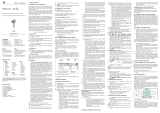
Pepperl+Fuchs FP-LB-I Operating instructions

Type
Operating instructions
DOCT-0258D 192382 03/2012
1
Subject to modifications without notice
Pepperl+Fuchs Group
www.pepperl-fuchs.com
USA: +1 330 486 0002
Singapore: +65 6779 9091
Copyright Pepperl+Fuchs
Germany: +49 621 776 2222
Operating Instructions
Surge Protection Barriers
Introduction
To protect the signal lines of field devices and systems in the
cabinet against lightning. Pepperl+Fuchs covers the complete
range of Surge Protection Barriers.
Figure 1 Various Surge Protection Barriers
Housing types
Depending on the location you have to protect, we offer 3
different versions of Surge Protection Barriers.
DIN rail mount modules (K-LB-*.**)
Compact housing, 12.5 mm wide
Protection of field devices and control
devices
Single and dual channel versions
Grounded versions for zener barrier
applications
Figure 2 Surge protection K-LB-*.**
Field mount modules (F*-LB-I)
Screw in type for field devices
Protection of field devices
½ NPT, M20 and PG13.5 threat
versions
Floating versions
Figure 3 Surge protection F*-LB-I
Plug-in modules (P-LB-*.*.*)
Plug-in version for the
20 mm devices of the
K-System
Protection of K-System
inputs
For isolated barriers and
signal conditioners
Single and dual channel
versions
Figure 4 Surge protection P-LB-*.*.*
FS-LB-I
56
78
12
34
M20x15
FS-LB-I
DOCT-0258D 192382 03/2012
2
Subject to modifications without notice
Pepperl+Fuchs Group
www.pepperl-fuchs.com
USA: +1 330 486 0002
Singapore: +65 6779 9091
Copyright Pepperl+Fuchs
Germany: +49 621 776 2222
Operating Instructions
Surge Protection Barriers
Mounting and grounding
The correct installation of the Surge Protection Barrier (SPB) is very important. It must be ensured that the unprotected wiring
does not influence the wiring on the protected side. Proper cable routing should ensure a sufficient cable distance between wires
of the unprotected, earth connected and protected side. Depending on the mounting place, there are different possibilities for
mounting and earthing.
To p o l o g y
To protect the electrical equipment in both the control room and the hazardous area, two Surge Protection Barriers must be
integrated into the intrinsically safe circuit loop. Following the international standard EN 60079-14, intrinsically safe circuits can
either be connected "at one point to the equipotential bonding system if this exists over the whole area in which the intrinsically
safe circuits are installed" or "isolated from earth". International Standard EN 60079-14 states "if intrinsically safe apparatus (field
devices, Surge Protection Barriers and intrinsically safe barriers) do not withstand the electrical strength test with at least 500 V
from earth, a connection to earth at the apparatus is to be assumed".
Figure 5 One point ground connection
+
-
I
P
Additional field housing
Equipotential bonding (if required)
Option 1 Option 2
Protected
electrical
equipment
Protected
field device
Local earth
Remote earth Plant earth
Main system earth
K-LB-*.*
F*-LB-I
K-LB-*.*G Zener Barrier
DOCT-0258D 192382 03/2012
3
Subject to modifications without notice
Pepperl+Fuchs Group
www.pepperl-fuchs.com
USA: +1 330 486 0002
Singapore: +65 6779 9091
Copyright Pepperl+Fuchs
Germany: +49 621 776 2222
Operating Instructions
Surge Protection Barriers
DIN rail mount modules (K-LB-*.**)
Figure 6 DIN rail mount module grounding
Field mount modules (F*-LB-I)
The screw-in F*-LB-I is screwed directly into the field device
using the spare cable entry. Three wires are connected in
parallel to the field device’s signals and earth line.
Figure 7 Field mount module grounding
Plug-in modules (P-LB-*.*.*)
Figure 8 Plug-in module grounding
Protection
Unprotected signal loop
Since lightning-induced signals show pulse characteristics,
standard circuit breakers or fuses are not able to sufficiently
protect the electrical equipment. It can also be used for
protection against other sources causing transient voltages
like devices changing voltages or currents during switching
events or exhibiting a non-linear behavior. These other
sources are energy storing inductive loads, such as
transformers, motors and drives. They can induce high
transient voltages and surge currents on conductors that can
damage connected equipment. Each electronic device in the
loop should be protected with a Surge Protection Barrier.
Figure 9 Unprotected signal loop
Protection of the field device
Two options are available for the protection of the field device:
Option 1
The standard DIN Rail mounted K-LB-*.** is located close to
the field device. It should be placed within a field enclosure
and mounted on a grounded rail. The SPB must be locally
bonded to control the local potential between the signal cables
and the structure.
Option 2
The screw-in F*-LB-I is screwed directly into the field device
using the spare cable entry. Three wires are connected in
parallel to the field device’s signals and earth line. This will
ensure a line-to-line and line-to-earth protection.
Protected
Unprotected
TransmitterTerminal box
GND
F*-LB-I
F*-LB-I
24 V
Input
DOCT-0258D 192382 03/2012
4
Subject to modifications without notice
Pepperl+Fuchs Group
www.pepperl-fuchs.com
USA: +1 330 486 0002
Singapore: +65 6779 9091
Copyright Pepperl+Fuchs
Germany: +49 621 776 2222
Operating Instructions
Surge Protection Barriers
Figure 10 Protection of the field device
Protection of control side (cabinet)
Protection without isolation
To protect the zener barrier, a non-isolated, separately
mounted Surge Protection Barrier must be installed and
connected to the intrinsically safe side of the zener barrier. The
barrier’s earth connection is made, following the described
guidelines, to the main system earth in parallel to the
equipment and zener barrier earth cable.
Figure 11 Protection without isolation
Protection with isolation
The entire intrinsically safe circuit is isolated from earth. The
intrinsically safe barrier is an isolated barrier and no
connection to the main system earth is necessary. To maintain
the intrinsically safe measurement loop galvanically isolated
from earth, an isolated Surge Protection Barrier must be
installed at both ends of the loop. This must be close to the
isolated barrier, connected to its intrinsically safe side in the
safe area and close to the field device in the hazardous area,
but outside Zone 0.
Figure 12 Protection with isolation
Figure 13 Protection with isolation
Model number description
DIN rail mount modules
Field mount modules
Plug-in modules
K-LB-1.30
Additional field housing
Option 1
Option 2
F*-LB-I
K-LB-*.*
24 V
Input
Safe area
Isolated Barrier
––.
GGrounded
6Rated voltage 6 V
30 Rated voltage 30 V
11-channel (2-wire protection)
22-channel (4-wire protection)
LB Lightning barrier
KDIN rail mount modules
––I
Intrinsic safety Ex "i"
LB Lightning barrier
FN Field mount modules with ½ NPT thread
FP Field mount modules with PG13.5 thread
FS Field mount modules with M20 x 1.5 thread
––..
Protected terminals
11-channel
22-channel
LB Lightning barrier
PPlug-in modules
P-LB-*.*.*
24 V
Input
Safe area
Isolated Barrier
DOCT-0258D 192382 03/2012
5
Subject to modifications without notice
Pepperl+Fuchs Group
www.pepperl-fuchs.com
USA: +1 330 486 0002
Singapore: +65 6779 9091
Copyright Pepperl+Fuchs
Germany: +49 621 776 2222
Operating Instructions
Surge Protection Barriers
Safety Information for K-LB-*.**
DIN rail mount modules
The corresponding data sheets, the Declaration of Conformity,
the EC-Type Examination Certificate and applicable
certificates (see data sheet) are an integral part of this
document.
Intended use
Laws and regulations applicable to the usage or planned
purpose of usage must be observed. Devices are only
approved for proper usage in accordance with intended use.
Improper handling will result in voiding of any warrantee or
manufacturer's responsibility.
Surge Protection Barriers are used as modules positioned
upstream in the circuit from the corresponding electrical
equipment. They make it possible to protect against
overvoltages originating from various causes (lightning strikes,
switching processes, etc.). This is achieved by diverting the
transient current and limiting the voltage throughout the
duration of the overvoltage surge. Various modules are
available for protecting 2 or 4 conductors.
Protection of operating personnel and the system is not
ensured if the product is not used in accordance with its
intended use.
Intrinsic safety circuits that were operated with circuits of other
types of protection may not be used as intrinsically safe
circuits afterwards.
Application
Surge Protection Barriers themselves can be installed within
the hazardous area of Zone 1. They can be used for
intrinsically safe circuits up to Ex ia IIC. The ignition protection
class is determined by the connected intrinsically safe circuit of
the corresponding electrical equipment.
Surge Protection Barriers are not used to separate intrinsically
safe circuits from non-intrinsically safe circuits.
Surge Protection Barriers must not be installed in dust Ex-
zones.
Installation and commissioning in
connection with hazardous areas
Commissioning and installation must be performed only by
specialists who are trained specifically for this purpose.
The quality of the ground is a significant precondition for
problem-free overvoltage protection. Short connections and
large cable cross-sections are basic requirements for effective
protection. These requirements can be fulfilled through the use
of appropriate accessories (see data sheets).
Potential compensation must be set up for Surge Protection
Barriers of types K-LB-*.*G along the intrinsically safe circuits
inside and outside of the hazardous area
Surge Protection Barriers modules are designed in the IP20
protection class in accordance with EN 60529 and must be
protected against adverse environmental conditions such as
splashed water or dirt beyond pollution degree 2.
Depending on the ignition protection class, the circuits of
Surge Protection Barriers may be directed in Zone 1 or 0.
Special attention must be paid to a secure separation from all
non-intrinsically safe circuits in this context. A shortest path
distance of at least 50 mm must be maintained between
intrinsically safe and non-intrinsically safe conducting terminal
blocks during assembly. The ignition protection class is
determined by the connected intrinsically safe circuit of the
corresponding electrical equipment.
The installation of the intrinsically safe circuits is to be
conducted in accordance with the relevant installation
regulations.
The respective maximum values of the field device, the Surge
Protection Barriers and the corresponding electrical
equipment as defined by explosion protection must be
observed for interconnecting with intrinsically safe electrical
equipment (proof of intrinsic safety). EN 60079-14/
IEC 60079-14 must be observed (where appropriate).
The highest ignition protection class to be reached is
¬II 2 (1) G Ex ia IIC T6
Temperature class
Explosion group
Protection level
Explosion protection
identification
Ga s a r e a
Category
Device group
Identification for availability of explosions
DOCT-0258D 192382 03/2012
6
Subject to modifications without notice
Pepperl+Fuchs Group
www.pepperl-fuchs.com
USA: +1 330 486 0002
Singapore: +65 6779 9091
Copyright Pepperl+Fuchs
Germany: +49 621 776 2222
Operating Instructions
Surge Protection Barriers
The EC-Type Examination Certificates or standard
certificates/approvals should be observed. It is especially
important to observe the "special conditions" if these are
included in the certificates.
The use of this device must not change the ignition protection
category of the supplying circuit. Thus, for example, ib circuits
must not enter Zone 0, even if they are controlled via this
device – unless otherwise stated in the related approval.
Repair and maintenance
The transfer characteristics of the devices remain stable over
long periods of time. This eliminates the need for regular
adjustment. Maintenance is not required.
Fault elimination
No changes can be made to devices that are operated in
hazardous areas. Repairs on the device are not allowed.
Isolation coordinates for devices with
Ex-certificate in accordance with EN 50020
and EN 60079-11
The devices are assessed for pollution degree 2 and
overvoltage category II according to EN 50178.
For additional details, see data sheets.
Ambient conditions
Ambient temperature
-30 °C to 60 °C (243 K to 333 K)
Exceptions see data sheets.
Storage temperature
-30 °C to 80 °C (243 K to 353 K)
Relative humidity
max. 75 % without moisture condensation
DOCT-0258D 192382 03/2012
7
Subject to modifications without notice
Pepperl+Fuchs Group
www.pepperl-fuchs.com
USA: +1 330 486 0002
Singapore: +65 6779 9091
Copyright Pepperl+Fuchs
Germany: +49 621 776 2222
Operating Instructions
Surge Protection Barriers
Safety Information for F*-LB-I
field mount modules
The corresponding data sheets, the Declaration of Conformity,
the EC-Type Examination Certificate and applicable
certificates (see data sheet) are an integral part of this
document.
Intended use
Laws and regulations applicable to the usage or planned
purpose of usage must be observed. Devices are only
approved for proper usage in accordance with intended use.
Improper handling will result in voiding of any warrantee or
manufacturer's responsibility.
Surge Protection Barriers are used as protective modules for
intrinsically safe field devices and the corresponding electrical
equipment. They make it possible to protect against
overvoltages originating from various causes (lightning strikes,
switching processes, etc.). This is achieved by diverting the
transient current and limiting the voltage throughout the
duration of the overvoltage surge.
Protection of operating personnel and the system is not
ensured if the product is not used in accordance with its
intended use.
Intrinsic safety circuits that were operated with circuits of other
types of protection may not be used as intrinsically safe
circuits afterwards.
Application
Surge Protection Barriers themselves can be installed within
the hazardous area of Zone 1. They can be used for
intrinsically safe circuits up to Ex ia IIC. The ignition protection
class is determined by the connected intrinsically safe circuit of
the corresponding electrical equipment.
Surge Protection Barriers must not be installed in dust Ex-
zones.
Installation and commissioning in
connection with hazardous areas
Commissioning and installation must be performed only by
specialists who are trained specifically for this purpose.
The quality of the ground is a significant precondition for
problem-free overvoltage protection. Short connections and
large cable cross-sections are basic requirements for effective
protection.
Depending on the ignition protection class, the circuits of
Surge Protection Barriers may be directed in Zone 1 or 0.
Special attention must be paid to a secure separation from all
non-intrinsically safe circuits in this context. A shortest path
distance of at least 50 mm must be maintained between
intrinsically safe and non-intrinsically safe conducting terminal
blocks during assembly. The ignition protection class is
determined by the connected intrinsically safe circuit of the
corresponding electrical equipment.
The installation of the intrinsically safe circuits is to be
conducted in accordance with the relevant installation
regulations.
The respective maximum values of the field device, the Surge
Protection Barriers and the corresponding electrical
equipment as defined by explosion protection must be
observed for interconnecting with intrinsically safe electrical
equipment (proof of intrinsic safety). EN 60079-14/
IEC 60079-14 must be observed (where appropriate).
The EC-Type Examination Certificates or standard
certificates/approvals should be observed. It is especially
important to observe the "special conditions" if these are
included in the certificates.
The use of this device must not change the ignition protection
category of the supplying circuit. Thus, for example, ib circuits
must not enter Zone 0, even if they are controlled via this
device – unless otherwise stated in the related approval.
Repair and maintenance
The transfer characteristics of the devices remain stable over
long periods of time. This eliminates the need for regular
adjustment. Maintenance is not required.
Fault elimination
No changes can be made to devices that are operated in
hazardous areas. Repairs on the device are not allowed.
Ambient conditions
Ambient temperature
-30 °C to 60 °C (243 K to 333 K)
Exceptions see data sheets.
Storage temperature
-30 °C to 80 °C (243 K to 353 K)
Relative humidity
max. 75 % without moisture condensation
The highest ignition protection class to be reached is
¬II 2 G Ex ia IIC T6
Temperature class
Explosion group
Protection level
Explosion protection identification
Ga s a r e a
Category
Device group
Identification for availability of explosions
DOCT-0258D 192382 03/2012
8
Subject to modifications without notice
Pepperl+Fuchs Group
www.pepperl-fuchs.com
USA: +1 330 486 0002
Singapore: +65 6779 9091
Copyright Pepperl+Fuchs
Germany: +49 621 776 2222
Operating Instructions
Surge Protection Barriers
Safety Information for P-LB-*.*.*
plug-in modules
The corresponding data sheets, the Declaration of Conformity,
the EC-Type Examination Certificate and applicable
certificates (see data sheet) are an integral part of this
document.
Intended use
Laws and regulations applicable to the usage or planned
purpose of usage must be observed. Devices are only
approved for proper usage in accordance with intended use.
Improper handling will result in voiding of any warrantee or
manufacturer's responsibility.
Plug-in terminal modules are used as modules positioned
upstream in the circuit from the corresponding electrical
equipment. They make it possible to protect against
overvoltages originating from various causes (lightning strikes,
switching processes, etc.). This is achieved by diverting the
transient current and limiting the voltage throughout the
duration of the overvoltage surge. Various modules are
available for protecting 2, 3, 4 or 6 conductors. The
assignment of input connections of plug-in terminal
modules/intrinsically safe equipment (binary or analog signals)
corresponds to that of the following related equipment (see the
corresponding data sheets). Plug-in terminal modules should
only be used in combination with a device of the K-System.
Protection of operating personnel and the system is not
ensured if the product is not used in accordance with its
intended use.
Intrinsic safety circuits that were operated with circuits of other
types of protection may not be used as intrinsically safe
circuits afterwards.
Application
Plug-in terminal modules can be installed within the hazardous
area of Zone 2/Div. 2. They can be used for intrinsically safe
circuits up to Ex ia IIC. The ignition protection class is
determined by the connected intrinsically safe circuit of the
corresponding electrical equipment.
Plug-in terminal modules are not used to separate intrinsically
safe circuits from non-intrinsically safe circuits.
Plug-in terminal modules must not be installed in dust Ex-
zones.
Installation and commissioning in
connection with hazardous areas
Commissioning and installation must be performed only by
specialists who are trained specifically for this purpose.
The quality of the ground is a significant precondition for
problem-free overvoltage protection. Short connections and
large cable cross-sections are basic requirements for effective
protection. These requirements can be fulfilled through the use
of appropriate accessories (see data sheets).
Plug-in terminal modules are designed in the IP20 protection
class in accordance with EN 60529 and must be accordingly
protected against adverse environmental conditions such as
splashed water or dirt beyond pollution degree 2.
Plug-in terminal modules can be installed inside the hazardous
area of Zone 2/Div. 2. Since plug-in terminal modules are
always used in combination with devices of the K-System, the
devices of the K-System must, in this case, be suitable for use
in Zone 2/Div. 2. The devices of the K-System must then be
installed only in Zone 2/Div. 2 if a corresponding Declaration of
Conformity for a named location or a manufacturer's
Declaration of Conformity is present. For information on
whether this condition has been met, please refer to the data
sheets for the devices of the K-System. The instruction
manual, the Declaration of Conformity of a named location or
the manufacturer's Declaration of Conformity of devices of the
K-System and the information in them must be followed.
Depending on the ignition protection class, the circuits of plug-
in terminal modules may be directed in Zone 1 or 0. Special
attention must be paid to a secure separation from all non-
intrinsically safe circuits in this context. A shortest path
distance of at least 50 mm must be maintained between
intrinsically safe and non-intrinsically safe conducting terminal
blocks during assembly. The ignition protection class is
determined by the connected intrinsically safe circuit of the
corresponding electrical equipment.
The installation of the intrinsically safe circuits is to be
conducted in accordance with the relevant installation
regulations.
The respective maximum values of the field device, the plug-in
terminal modules and the corresponding electrical equipment
as defined by explosion protection must be observed for
interconnecting with intrinsically safe electrical equipment
(proof of intrinsic safety). EN 60079-14/
IEC 60079-14 must be observed (where appropriate).
DOCT-0258D 192382 03/2012
9
Subject to modifications without notice
Pepperl+Fuchs Group
www.pepperl-fuchs.com
USA: +1 330 486 0002
Singapore: +65 6779 9091
Copyright Pepperl+Fuchs
Germany: +49 621 776 2222
Operating Instructions
Surge Protection Barriers
The EC-Type Examination Certificates or standard
certificates/approvals should be observed. It is especially
important to observe the "special conditions" if these are
included in the certificates.
The terminal modules must be installed in such a way that they
are protected from electrostatic charge.
The use of this device must not change the ignition protection
category of the supplying circuit. Thus, for example, ib circuits
must not enter Zone 0, even if they are controlled via this
device – unless otherwise stated in the related approval.
Repair and maintenance
The transfer characteristics of the devices remain stable over
long periods of time. This eliminates the need for regular
adjustment. Maintenance is not required.
Fault elimination
No changes can be made to devices that are operated in
hazardous areas. Repairs on the device are not allowed.
Isolation coordinates for devices with
Ex-certificate in accordance with EN 50020
and EN 60079-11
The devices are assessed for pollution degree 2 and
overvoltage category II according to EN 50178.
Ambient conditions
Ambient temperature
-20 °C to 60 °C (253 K to 333 K)
Storage temperature
-25 °C to 70 °C (248 K to 343 K)
Relative humidity
max. 75 % without moisture condensation
Technical data
For details, see data sheets.
  • Page 1 1
  • Page 2 2
  • Page 3 3
  • Page 4 4
  • Page 5 5
  • Page 6 6
  • Page 7 7
  • Page 8 8
  • Page 9 9

Pepperl+Fuchs FP-LB-I Operating instructions

Type
Operating instructions

Ask a question and I''ll find the answer in the document

Finding information in a document is now easier with AI