Page is loading ...

1
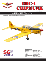
Specications:
Wingspan ----------------- 64 in---------------------- 162.5 cm.
Wing Area ---------------- 846 sp.in----------------- 54.6 sq.dm.
Weight --------------------- 9.3 lbs-------------------- 4.2 kg.
Length --------------------- 61.4 in-------------------- 156 cm.
Engine size .91-1.25 cu.in- 2-4stroke / 20cc gasoline engine.
Radio System------------- 5 channel with 5 digital servos.
ASSEMBLY MANUAL
Code : SEA 387

YAK 54 ARF 20cc Instruction Manual.
2
1
ank you for choosing the YAK 54 ARF 20cc ARTF by SG MODELS. e YAK 54
ARF 20cc was designed with the intermediate/advanced sport yer in mind. It is a semi
scale airplane which is easy to y and quick to assemble. e airframe is conventionally
built using balsa, plywood to make it stronger than the average ARTF, yet the design allows
the aeroplane to be kept light. You will nd that most of the work has been done for you
already. e motor mount has been tted and the hinges are pre-installed. Flying the YAK
54 ARF 20cc is simply a joy.
is instruction manual is designed to help you build a great ying aeroplane. Please read
this manual throughly before starting assembly of your YAK 54 ARF 20cc Use the parts
listing below to indentify all parts.
If you are inexperienced with basic R/C ight we strongly recommend you contact your
R/C supplier and join your local R/C model Flying Club. R/C Model Flying Clubs oer a
variety of training procedures designed to help the new pilot on his way to successful R/C
ight. ey will also be able to advise on any insurance and safety regulations that may
apply.
Please be aware that this aeroplane is not a toy and if assembled or used incorrectly it is
capable of causing injury to people or property. WHEN YOU FLY THIS AEROPLANE
YOU ASSUME ALL RISK & REPONSIBILITY.
INTRODUCTION
WARNING
KIT CONTENTS
2
2
3
7
8
9
3
5
10
11
13
6
4
12

3
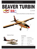
KIT CONTENTS
SEA387 YAK 54 ARF 20cc
1. Fuselage
2. Wing set (2)
3. Tail set (2)
4. Canopy
5. Cowling
6. Wing tube
7. landing gear
8. Fuel tank
9. Tail wheel
10. Pushrod
11. Ep Motor box
12. Pilot
13. Spinner
ADDITIONAL ITEMS REQUIRED
TOOLS & SUPPLIES NEEDED
in cyanoacrylate glue.
Medium cyanoacrylate glue.
30 minute epoxy.
5 minute epoxy.
Hand or electric drill.
Assorted drill bits.
Modelling knife.
Straight edge ruler.
2mm ball driver.
Phillips head screwdriver.
220 grit sandpaper.
90° square or builder’s triangle.
Wire cutters.
Masking tape & T-pins.
read-lock.
Paper towels.
� 20cc gasoline engine.
� Computer radio 5 channel with 5
servos.
� Glow plug to suit engine.
� Propeller to suit engine 20x8-21x10.
� Protective foam rubber for radio
system.
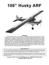
HINGING THE AILERON
Note : e control surfaces, including the ailer-
ons, elevators, and rudder, are prehinged with
hinges installed, but the hinges are not glued in
place. It is imperative that you properly adhere
the hinges in place per the steps that follow us-
ing a high-quality thin C/A glue.
Carefully remove the aileron from one of
the wing panels. Note the position of the
hinges.
1.
C/A Hinge
Remove each hinge from the wing panel
and aileron and place a T-pin in the center
of each hinge. Slide each hinge into the wing
panel until the T-pin is snug against the wing
panel. is will help ensure an equal amount
of hinge is on either side of the hinge line
when the aileron is mounted to the aileron.
Slide the wing panel on the aileron until
there is only a slight gap. e hinge is now
centered on the wing panel and aileron.
Remove the T-pins and snug the aileron
against the wing panel. A gap of 1/64” or
less should be maintained between the
wing panel and aileron.
2.

YAK 54 ARF 20cc Instruction Manual.
4
6.
7.
3.
4.
5.
NOTE : e hinge is constructed of a spe-
cial material that allows the C/A to wick
or penetrate and distribute throughout
the hinge, securely bonding it to the wood
structure of the wing panel and aileron.
Deect the aileron and completely saturate
each hinge with thin C/A glue. e ailerons
front surface should lightly contact the wing
during this procedure. Ideally, when the
hinges are glued in place, a 1/64” gap or less
will be maintained throughout the lengh of
the aileron to the wing panel hinge line.
Turn the wing panel over and deect the
aileron in the opposite direction from the
opposite side. Apply thin C/A glue to each
hinge, making sure that the C/A penetrates
into both the aileron and wing panel.
Using C/A remover/debonder and a paper
towel, remove any excess C/A glue that may
have accumulated on the wing or in the
aileron hinge area.
Repeat this process with the other wing
panel, securely hinging the aileron in place.
Aer both ailerons are securely hinged,
rmly grasp the wing panel and aileron to
make sure the hinges are securely glued and
cannot be pulled out. Do this by carefully ap-
plying medium pressure, trying to separate
the aileron from the wing panel. Use caution
not to crush the wing structure.
Work the aileron up and down sev-
eral times to “work in” the hinges
and check for proper movement.
Note :
CA glue
Hinge

5
Locate the aileron control horns. e taller
control horn is used for the ailerons, and the
shorter horn for the aps.
Use sandpaper to scu the bottom of the
aileron and ap control horns. Use a paper
towel and isopropyl alcohol to remove any
oils or debris from the control horns.
Check the t of the control horns to
the aileron and ap. ey should rest ush
against the control surface as shown.
INSTALL THE AILERONS
CONTROL HORN
1.
2.
3.
Ailerons control horn
Place low-tack tape 1/32 inch (1mm)
from the control horn slot. is will pre-
vent epoxy from getting on the control
surface when the control horns are glued
in place.
Apply epoxy to the area of the control
horns that st into the slots. Use enough
epoxy so the control horns will be fully
bonded to the ed surfaces.
Remove the control horns from the
control surfaces. Apply epoxy to the slot
in the aileron and ap. Make sure the
epoxy gets into the slot for a good bond
between the surfaces and control horn.
4.
5.
6.
Epoxy
Epoxy

YAK 54 ARF 20cc Instruction Manual.
6
Before the epoxy fully cures, remove
the tape from around the control horn.
is will allow the epoxy to ow around
the control horn, creating a small let
between the control horn and surface for
a ished look and secure bond.
Because the size of servos dier, you
may need to adjust the size of the precut
opening in the mount. e notch in the
sides of the mount allow the servo lead to
pass through.
Install the rubber grommets and brass
collets onto the aileron servo. Test t the
servo into the aileron servo mount.
7.
Use dental oss to secure the connec-
tion so they cannot become unplugged.
Using a small weight (Weighted fuel
pickup works well) and thread, feed the
string through the wing as indicated.
3.
Attach servo lead to the aileron servo.
Attach the string to the servo lead and
carefully thread it though the wing. Once
you have thread the lead throught the
wing, remove the string so it can use for
the other servo lead.
4.
INSTALLING THE AILERON SERVOS
1.
2.
Maximum Servo spec.
Torque : 126.6 oz-in (9.11 kg-cm) @ 6.0V;
178 oz-in (12.82 kg-cm) @ 7.4V; 248 oz-
in (17.86 kg-cm) @ 8.4V

7
Tape the servo lead to the wing to pre-
vent it from falling back into the wing.
5.
Reinstall the servo into the servo mount
and secure the servo inplace using the
wood screws provided with you radio
system.
Repeat the procedure for the other wing
half.
6.
7.
8.
9.
11.
10.
25mm

YAK 54 ARF 20cc Instruction Manual.
8
Repeat all the above steps for the other
wing.
3.
2.
5.
4.
6.
65mm
INSTALLING THE AILERON PUSHROD
Please study images below.
1.
INSTALL HINGE FOR STABILIZER
AND ELEVATOR
Please study images below.
1.

9
4.8.
5.
3.7.
6.
2.
40mm40mm
Epoxy
9.
CA glue

YAK 54 ARF 20cc Instruction Manual.
10
10.
11.
12.
INSTALL ELEVATOR CONTROL HORN
1.
2.
Fiberglass control horn
3.
4.
Epoxy
Epoxy
5.

11
7.
6.
9.
10.
11.
Maximum Servo spec.
Torque : 126.6 oz-in (9.11 kg-cm) @ 6.0V;
178 oz-in (12.82 kg-cm) @ 7.4V; 248 oz-
in (17.86 kg-cm) @ 8.4V
13.
12.

YAK 54 ARF 20cc Instruction Manual.
12
14.
15.
16.
21.
18.
19.
17.
20.

13
1.
INSTALLING THE HORIZONTAL
STABILIZER
Using a ruler and a pen, locate the cen-
terline of the horizontal stabilizer, at the
trailing edge, and place a mark. Use a tri-
angle and extend this mark, from back to
front, across the top of the stabilizer. Also
extend this mark down the back of the
trailing edge of the stabilizer.
Draw center line
Using a modeling knife, carefully re-
move the covering at mounting slot of
horizontal stabilizer ( both side of fuse-
lage).
2.
3.
Slide the stabilizer into place in the
precut slot in the rear of the fuselage. e
stabilizer should be pushed rmly against
the front of the slot.
Cut
With the stabilizer held rmly in place,
use a pen and draw lines onto the stabi-
lizer where it and the fuselage sides meet.
Do this on both the right and le sides
and top and bottom of the stabilizer.
4.
Pen
5.
Remove the stabilizer. Using the lines
you just drew as a guide, carefully remove
the covering from between them using a
modeling knife.
Trim and cut

YAK 54 ARF 20cc Instruction Manual.
14
6.
When cutting through the covering
to remove it, cut with only enough pressure
to only cut through the covering itself. Cut-
ting into the balsa structure may weaken
it.
Using a modeling knife, carefully re-
move the covering that overlaps the sta-
bilizer mounting platform sides in the
fuselage. Remove the covering from both
the top and the bottom of the platform
sides.
When you are sure that everything is
aligned correctly, mix up a generous
amount of 30 Minute Epoxy. Apply a thin
layer to the top and bottom of the stabi-
lizer mounting area and to the stabilizer
mounting platform sides in the fuselage.
Slide the stabilizer in place and realign.
Double check all of your measurements
once more before the epoxy cures. Hold
the stabilizer in place with T-pins or mask-
ing tape and remove any excess epoxy us-
ing a paper towel and rubbing alcohol.
Epoxy
.
Epoxy
7.
8.
HINGING THE RUDDER
Glue the top three rudder hinges in
place using the same techniques used to
hinge the elevator.
e lower hinge will be glued when the
n/rudder assembly is attached to the fu-
selage.
1.
2.

15
4.
3.
CA glue
1.
INSTALL RUDDER CONTROL HORN
Repeat steps to install the rudder control
horn as same as steps done for elevator.
Fiberglass control horn
3.
2.
Epoxy
4.
5.

YAK 54 ARF 20cc Instruction Manual.
16
1.
2.
3.
INSTALLING VERTICAL STABILIZER
Using a modeling knife, remove the
covering from over the precut hinge slot
cut into the lower rear portion of the fu-
selage. is slot accepts the lower rudder
hinge.
Remove covering
Slide the vertical stabilizer into the slot in
the top of the fuselage. e rear edge of the
stabilizer should be ush with the rear edge
of the fuselage and the lower rudder hinge
should engage the precut hinge slot in the
lower fuselage. e bottom edge of the stabi-
lizer should also be rmly pushed against the
top of the horizontal stabilizer.
Fill Epoxy
6.
Epoxy
7.
Rudder berglass control horn
4.
While holding the vertical stabilizer
rmly in place, use a pen and draw a
line on eachside of the vertical stabilizer
where it meets the top of the fuselage.
Hinge slot

17
5.
6.
7.
Slide the vertical stabilizer back inplace.
Using a triangle, check to ensure that the
vertical stabilizer is aligned 90º to the
horizontal stabilizer.
90º
Vertical
Stabilizer.
Horizontal
Stabilizer.
When you are sure that everything is
aligned correctly, mix up a generous
amount of Flash 30 Minute Epoxy. Ap-
ply a thin layer to the mounting slot
and to bottom of the vertical stabilizer
mounting area. Apply epoxy to the bot-
tom and top edges of the ller block and
to the lower hinge also. Set the stabilizer
in place and realign. Double check all of
your measurements once more before
the epoxy cures. Hold the stabilizer in
place with T-pins or masking tape and
remove any excess epoxy using a paper
towel and rubbing alcohol. Allow the
epoxy to fully cure before proceeding.
Epoxy
ELEVATOR PUSHROD
INSTALLATION
1.
2.
125mm
3.
4.

YAK 54 ARF 20cc Instruction Manual.
18
3.
4.
1.
1.
2.
Locate items necessary to install rudder
pushrod.
RUDDER PUSHROD
INSTALLATION
95mm
Locate items necessary to install
tailwheel.
TAILWHEEL INSTALLATION
3.
2.
2mm

19
4.
5.
6.
M3x15mm
C/A glue
M3x12mm
7.
8.
9.
10.
11.

YAK 54 ARF 20cc Instruction Manual.
20
12.
13.
2.
3.
4.
5.
INSTALLING THE MAIN LANDING
GEAR TO FUSELAGE
1.
Please study images below.
/