Page is loading ...


Installation and Maintenance Instructions
Saf-T Vent® Model EZ Seal/EZ 316
Single Wall
Gas Vent Connector
Chimney Liner &
Special Gas Vent (USA) / Type BH Vent Class I/II (Canada)
For Venting Residential, Commercial & Industrial Appliances
Category I, II, III & IV Appliances
3”-5” Diameter Vent for use on Positive, Neutral and Negative
Pressures up to 9” W.C.
Important: Do NOT install this product until you have read and fully understand these installation
instructions. Failure to comply with these instructions may result in injury or damage to property. An
improper installation will void any stated warranty.
• Follow these instructions exactly as written.
• Examine all components for possible shipping damage prior to installation.
• Proper joint assembly is essential for a safe installation. Check integrity of joints upon
completion of assembly.
• This venting system must be supported in accordance with these instructions.
• Check for restricted vent movement through the walls, ceilings and roof penetrations.
This venting system must be free to expand and contract.
• Do not mix Saf-T vent pipe with pipe from different manufacturers.
5030 Corporate Exchange Blvd
Grand Rapids, MI 49512
Call 800 772-0739
Fax 800 972-1421
www.heatfab.com
Tested and Listed to
UL1738 & ULC S636
By Underwriters Laboratories, Inc.

PI-EZINS 4/17
APPLICATION INFORMATION
Saf-T Vent Model EZ Seal/EZ 316 Gas Vent Systems may be used to vent safety certified Category I, II, III, IV
and Certain Direct Vent gas appliances with a flue gas temperature of not more than 550° F (288° C). When used
as a masonry chimney liner, Saf-T Vent EZ Seal/EZ 316 can be used to vent condensing oil appliances and
category I, II, III, IV gas fired appliances. The Saf-T Vent EZ Seal/EZ 316 system is for use with appliances which
produce positive vent pressures of 9 inches of water column or less. Saf-T Vent Model EZ Seal and EZ 316
components are compatible and may be combined for installations. Because these types of appliances may
produce vent gases under positive pressure and/or at or near their dew point, special installation considerations
may be required. Install in accordance with these instructions and those of the appliance manufacturer. Consult
the appliance manufacturer’s instructions for the maximum horizontal length of the vent connector as well as any
restriction on total vent height, proper sizing of the vent, common venting considerations and procedures for
connecting the vent to the appliance.
The installation must conform to applicable National, Regional, State and local codes. Contact the Authority
Having Jurisdiction prior to beginning any work to obtain any required permits.
Pre-Installation Considerations:
Proper planning prior to installation is essential for maintaining proper clearances and for avoiding possible
contact with concealed plumbing or electrical wiring inside walls, floors and ceilings. A continuous straight-line
upward pitch of at least 1/4 inch (2 degrees) rise per foot on horizontal runs must be maintained in order to
properly rid the system of the corrosive condensate. Be sure to plan a sufficient number of supports for the entire
system to maintain the required straight-line pitch and to hold the system in place. Where the vent is enclosed
within a chase, the enclosures should be built to permit future inspection of the system.
Reference Combustion & Ventilation Air on the last page for proper air supply guidelines
Personal Safety
Wear eye protection and heavy gloves throughout the installation. In addition, wear an approved dust and vapor
respirator whenever in contact with building insulation. Proper and safe scaffolding and/or ladders should be
used. Check overhead for antennas, power lines or other obstacles before erecting ladders or scaffolding and
while working with conduit on any roof structure.
Tools Required for Installation
Common building tools including but not limited to a Tape Measure, Pliers, Screw Drivers, Saws and/or Snips,
Drills, Drop Cloth(s); Ladder/Scaffold; Safety and Personal Protective Clothing.
Definitions:
AL 29-4C – The inner wall material for EZ Seal (excludes EZ 316) is a super ferritic stainless steel alloy designed
by Allegheny Ludlum for extreme resistance to chloride ion pitting, crevice corrosion and stress corrosion
cracking. Equivalent material made by other manufacturers may be identified by the UNS designator S44735.
316L – An austenitic chromium-nickel stainless steel containing molybdenum. Type 316L is an extra-low carbon
version of Type 316 that minimizes harmful carbide precipitation due to welding. Type 316L is used in
applications where immunity to carbide precipitation due to welding assures optimum corrosion resistance.
316L may be identified by the UNS designator S31603.
Category I Appliance - An appliance which operates with a non-positive vent static pressure and with a vent gas
temperature that avoids excessive condensate production in the appliance.
Category II Appliance - An appliance which operates with a non-positive vent static pressure and with a vent gas
temperature that may cause excessive condensate production in the appliance.
Category III Appliance - An appliance that operates with a positive vent static pressure and with a vent gas
temperature that avoids excessive condensate production in the appliance.
Category IV Appliance - An appliance that operates with a positive vent static pressure and with a vent gas
temperature that may cause excessive condensate production in the appliance.
Combustible Material - Any material made of or surfaced with wood, compressed paper, plant fibers, or other
materials that are capable of being ignited or burned. Such material shall be considered combustible even
though it is flame proofed, fire-retardant treated, or plastered. (Source: NFPA54/ ANSI Z223.1-2006.).

PI-EZINS 4/17
Clearance to Combustibles and Framing Requirements
Table 1 shows the required MINIMUM AIRSPACE CLEARANCE TO COMBUSTIBLES. “Combustibles” include
framing lumber, drywall, plywood, paneling, insulation, wiring and other building materials. This airspace
clearance is required for safe operation of the vent. Failure to follow these clearances could overheat the building
materials and could cause fire.
Max Appliance
Flue Gas
Temperature Vertical Horizontal Vertical Horizontal
3" - 5" 230°F* 0" 0" 0" 0"
3" & 4" 480°F 4" 8" 1" 1"
3" & 4" 550°F 4" N/A 1" 1"
400°F 4" N/A 1" 1"
480°F 5" N/A 1" 1"
550°F 6" N/A 1" 1"
* per ULC-S636
Pipe Size
Minimum Clearance
Enclosed Vent
Unenclosed Vent
5"
Table 1. Minimum Clearance to Combustibles
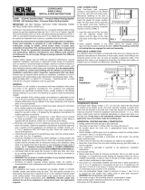
Vertical (Floor, Ceiling and Roof) Penetrations
Where the vent passes through a floor, ceiling or roof, the hole size or framing dimension must maintain minimum
clearances per Table 1. Floor and Ceiling penetrations require a Fire Stop be installed. See Fire Stop section for
installation instructions.
Horizontal (Wall) Penetrations
Horizontal systems passing through a combustible wall
require the use of a Wall Thimble, for relative
temperatures with clearances. See Table 2 for proper
framing dimensions and refer to Wall Thimble section for
installation instructions. Non-combustible wall
penetrations do not require a Wall Thimble.
TYPICAL INSTALLATIONS
Horizontal Support
Combustible
Enclosure
Rain Cap or other Termination
Flashing & Storm Collar
Firestop
Unenclosed Attic
See Table 1. (Min.
Clearance for Unenclosed
Vertical Vent)
See Table 1. (Clearance for
Enclosed Vertical Vent)
Fig 1. (Vertical Termination)
See Table 1.
(Clearance for
Unenclosed
Horizontal Vent)
See Table 1.
(Clearance for
Unenclosed
Vertical Vent)
See Table 1. (Clearance for
Enclosed Horizontal Vent)
See Table 2. (Min.
Framing Dimension for
Wall Thimble)
Fig 2. (Horizontal Termination)
Wall Thimble
Termination
Elbow
Firestop
Firestop &
Support Clamps
Support Clamps
Pipe Minimum Framing Dimensions
Size Wall Thimble
3" 6.5" x 6.5"
4" 6.5" x 6.5"
5" 10" x 10"
Table 2. (Minimum Framing Dimension)

PI-EZINS 4/17
In addition to the configurations shown in Figs. 1 & 2, this system may be installed in any combination of vertical
and horizontal, enclosed and unenclosed configurations as long as minimum clearances are maintained per
clearance Tables 1 & 2 and the total length and number of fittings does not exceed the appliance manufacturer’s
recommendations. This system may also be installed within an existing masonry chimney.
Notes:
1. Unenclosed systems require at least one side open (combustible material on maximum of 3 sides).
2. Reduced clearances may be attained by using noncombustible enclosures.
3. Do not place insulation in any required clearance spaces surrounding the vent system unless these
instructions suggest otherwise and the insulation is specified or supplied.
VENT ROUTING LIMITATIONS - MAXIMUM EQUIVALENT LENGTHS
In order to insure the vent system is not overly restrictive to flow, refer to the maximum length of vent specified by
the appliance manufacturer. In order to account for turns in the system (which cause additional resistance to
flow) most manufacturers recommend using an “Equivalent Length” method of determining the limitations. Via
such method, elbows and tees are assigned an “equivalent length” (in feet). If the sum of straight length segments
and additional “equivalent lengths” (due to turns) exceeds the limit specified
by the manufacturer, the routing is not permitted. See appliance
manufacturer’s instructions for additional information.
If the appliance manufacturer’s instructions do not list equivalent lengths for
standard fittings, use Table 3 to determine the Equivalent Length of the vent
fittings.
GENERAL INSTALLATION REQUIREMENTS
1. In instances where the appliance manufacturer’s instructions conflict
with requirements in this document, the appliance manufacturer’s
instructions take precedence.
2. Failure to conform to any of these requirements may violate local, state
or national codes as well as create conditions which may cause catastrophic property damage and/or
personal injury.
3. The horizontal vent connector must slope upward toward the termination at least 1/4 inch per foot and be
installed so that all condensate runs back toward the appliance or inline drain and is not retained in any part
of the venting system.
4. If called for by the appliance manufacturer’s instructions, a drain fitting must be located as close as possible
to the appliance flue outlet. Additional drains are required for each 30’ of vent. If a drain fitting is not
supplied with the appliance, install a Saf-T Vent in-line drain or a tee with a drain tee cover. Properly
dispose of collected condensate.
5. Multiple Category III or IV appliances may not be interconnected to any part of the venting system unless
the appliance manufacturer has specifically approved the engineering of the vent system. A Category III or
IV appliance may not be interconnected to any part of a vent system used with a natural draft or draft hood
appliance, except when a listed mechanical draft system is installed.
6. For venting systems that extend through any zone above that on which the connected appliance is located
(except for one and two family dwellings), codes require that the vent system be enclosed with an enclosure
having a fire resistance rating equal to or greater than that of the floor or roof assemblies through which it
passes. In one and two family residential construction the system must be enclosed whenever passing
through occupied spaces. The enclosure should be fabricated to allow periodic inspection of the vent.
7. Whenever gas-burning equipment is installed in the same space where halogenated substances may exist
(refrigerants, solvents, bleaches, salts, etc.), clean outside air must be utilized for combustion.
8. When passing 5’ or more of vent through an unheated area (such as attics, crawl spaces, building exteriors
or above roof lines), it is recommended that the system be converted to double wall CI Plus (or SC for 3”
and 4” pipe) to prevent condensation and freezing. Any penetrations of ceilings, floors, or walls must be
properly fire-stopped.
9. The vent system shall not be routed into, through or within any other actively used vent or chimney.
10. Another appliance may not vent into the flue space outside the Saf-T Vent conduit. However, if there is
sufficient space and all manufacturer’s instructions and codes are followed, a separate chimney liner may
be installed within the chimney to vent another appliance.
Equivalent Length Table
Fitting
Equivalent
Length
Straight Length
1’ per 1’
Boot Tee
10’
90 Degree Elbow
10’
70 Degree Elbow
8’
45 Degree Elbow
5’
30 Degree Elbow
4’
15 Degree Elbow
3’
Table 3

PI-EZINS 4/17
Fig 5. (Ring and Tab Connection)
Ring
Tab
Tabs Under Ring
Fold Tabs
Over Ring
HORIZONTAL INSTALLATION REQUIREMENTS
1. If the termination is through a combustible wall, the system must terminate with a Saf-T Vent Wall Thimble
and a Saf-T Vent termination as required by the appliance manufacturer.
2. The horizontal termination shall be located not less than 12 inches above grade or anticipated snow line
(remember to consider snow and ice falling from overhead objects), and not less than 7 feet above grade
when located adjacent to a public walkway. It shall also terminate a minimum of 4 feet below, 4 feet
horizontally from, or 1 foot above any door, window, fresh air intake, utility meter or regulator unless the
appliance is Listed differently. The termination must be a minimum of 6 feet from the combustion air intake
of any other appliance. Proper judgment may require greater distances depending on the size of the
equipment installed or site conditions. Consult with the local Authority Having Jurisdiction.
3. The termination should be away from trees,
shrubs, or decorative items as flue gases
could cause damage.
4. The total equivalent horizontal distance of
the vent system from the appliance flue
collar to the outside of the termination shall
not be less than 14 inches.
5. A minimum of one (1) horizontal support is
required for every 6 feet of run.
VERTICAL INSTALLATION REQUIREMENTS
1. The vent system must terminate at least 3
feet above the roof line and at least 2 feet
higher than any portion of the building within
10 feet.
2. When terminated at a height of more than 6 feet above the roof, the vent must be supported by a Saf-T
Vent Guy Section. Refer to the Guy Support section of these installation instructions.
3. The vent system must terminate with one of the Saf-T
Vent Terminations; except when a Termination or
approved mechanical vent device is specified or
provided by the appliance manufacture.
4. The total continuous distance of the vent system from
the appliance flue collar to the termination shall not
exceed that specified in the appliance manufacturer’s
installation instructions. When venting natural draft
appliances the termination must be at least 5 feet
above the topmost draft hood. Otherwise a Listed
mechanical draft inducing device is required.
5. Vertical supports are required after every transition to
vertical and as specified in Table 4. Vertical supports
are also required above every offset elbow. See Table
4 for vertical support limits.
JOINT SEALING AND CONNECTION METHOD
Model EZ Seal/EZ 316 (Diameters 3" thru 16") is manufactured
with a factory installed seal on the inside of the female (outlet)
end making the use of any additional sealant unnecessary.
Connection
Note: It is required to apply gasket lubricant (p/n 7001SIL-5, sold
separately) to the factory installed silicone gasket when
assembling the pipe. Apply lubricant directly to the gasket on the
inside female pipe end, both edges of gasket.
1. Connect parts using the Ring and Tab Connection
Method. See Fig 5.
1 Ft. Above Doors & Windows
4 Ft. Horizontally from
Doors and Windows
4 Ft. Below any
window or fresh
air inlet.
7 Ft. Above Public
Walkways and Drives
1 Ft. above ground
or snow line Sidewalk
Fig 3. (Horizontal Installation Requirements)
Fig 4. (Vertical Installation Requirements)
2'
10'
(2 Ft. Above Structures within 10 Ft.)

PI-EZINS 4/17
a. To connect, slide the lock ring away from the end to allow clearance for the tabs extending from
the female end.
b. Engage the two sections making sure the tabs stay to the outside of the vent.
c. After the sections are fully engaged, slide the lock ring down over the tabs, making sure all tabs
are contained within the lock ring.
d. Bend the tabs back over the lock ring to complete the joint. Note: Some termination parts have a
hose clamp in place of the lock ring. In such cases, the hose clamp is tightened down over the
tabs. The tabs need not be bent over the clamp.
Condensate Drains:
When An Internal Condensate Drain Is NOT Part of the
Appliance:
• A Saf-T Vent In-Line Drain Section, Tee or Boot Tee with
a separate Tee Cover Drain is strongly recommended.
Install this drain fitting as close to the appliance flue
collar as possible (See Fig. 6A).
• Use the Boot Tee to transition from horizontal to vertical
and attach the Drain Tee Cover to the appropriate leg of
the tee (See Fig 6A).
• A condensate drain is required for every 30 feet of
horizontal vent and at/near the bottom of a vertical stack.
• Use the In-Line Drain Section for a straight horizontal
run. Rotate the fitting so that the drain tube points
downward and is as vertical as possible (See Fig. 6B).
• A Condensate Drain Tube Kit is available to drain the
condensate to an appropriate location (i.e. floor drain or
vented sanitary sewer connection). A trap loop must be
formed into the drain hose and must be a diameter that is
at least four times the appliance's rated stack pressure in
inches of water column or 3 inches, whichever is greater.
Secure the loop with a cable tie. Prior to final assembly
the trap loop must be 'primed' by pouring a small quantity
of water into the drain hose.
• Follow all local and national codes and regulations for the draining of acidic condensate.
• In cold climates do not install a condensate drain on the exterior of the building. Doing so may result in
dangerous icy conditions on surfaces near the drain and may cause damage to the vent system and/ or
the building exterior. We will NOT be held liable for any injury or property damage due to formation of ice.
Adjustable Section:
The Saf-T Vent EZ Seal/EZ 316 Adjustable Length Section serves as a
variable length between other components when specific lengths cannot
be utilized and eliminates the need to cut parts to length. To install, refer
to installation instructions included with the Adjustable length.
Customized Lengths— Cutting Standard Lengths
The Saf-T Vent EZ Seal/EZ 316 system is designed so that in most
cases standard lengths will not need to be cut. There may arise,
however, an occasional situation where standard lengths and
adjustable length slip connectors are not adequate. In such cases, a
standard length of Saf-T Vent may be field cut.
To custom cut a standard length part:
1. Measure the length of vent needed (Dim A) and add 3
inches to the result.
2. Measuring from the female end (end with the tabs) measure
out the distance A + 3" and mark it on the pipe.
Fig 7. (Adjustable Length)
Fig 6B. (In-Line Drain Sectionand Drain Tube)
Fig 6A. (Boot Tee w/ Drain Cover & Tube)
Boot Tee
Drain Tube
Drain Tube
w/ Trap Loop
Drain Section
A + 3"
Cut Here
A
Non-Standard Length
Required
Fig 8. (Cutting Standard Lengths)
Standard Length

PI-EZINS 4/17
3. Cut the pipe with an abrasive cutoff, plasma, or compound snips.
To help get a square cut, create a straightedge by
wrapping masking tape around the waste side of
the cut point. If
using snips, start the cut at the male end and
follow a spiral path
around the pipe until the cutoff mark is reached.
4. File off any burrs that develop in the cutting
process prior to assembling. If the cutting process
distorts the roundness of the pipe carefully use
your thumbs to re-round the end.
5. Apply high-temperature silicone sealant to the
field-cut joint.
6. Assemble the joint using the procedures above.
7. A hose clamp must be used to retain the tabs.
Vertical and Horizontal Support
For proper installation, Vertical and/or Horizontal supports
must be installed to support the Saf-T Vent. Refer to Table
4 for minimum spacing distances and the corresponding
section for instructions for installing the support. Note: For
all support options, ensure all minimum clearance to
combustibles are maintained. Never drill or screw through
the Saf-T Vent system.
Guy Support Section
The Guy Support is a short section of vent pipe with brackets protruding
from it. These brackets provide a means for attaching a guy line,
threaded rod or similar metal bracing to provide support to the vent
system.
To Install: Connect Guy Section to the vent using standard joint
connection method. Attach guy wires or metal bracing to the brackets
provided on the Guy Section. Anchor guy wires or bracing to the
building infrastructure capable of supporting the load of the vent (See
Fig. 9).
Fire Stop
Wherever the vent passes through a ceiling or floor a Fire Stop (5x18CI)
must be installed. To Install: Establish the correct framing dimension
(See Table 1) and nail the Fire Stop to the joist (Fig 10). Route the vent
through the Fire Stop plate.
Caution about insulation in attics – Note: When installing a Fire Stop in the attic, the Fire Stop should be located
on the top of the joist to prevent insulation from falling into the joist. Keep all attic insulation the proper
minimum clearance from pipe by installing an enclosure or similar around the pipe.
Support Clamps
Support Clamps may be suspended from rods or cables and used as a
saddle to rest the vent in or they may be used in pairs to clamp around
the vent and suspended from a single rod, cable (See Fig. 11).
Spacing Between Supports
Diameters
Vertical
Spacing
Horizontal Spacing
3” thru 5” 30’
Every six (6) feet and
after every transition from
vertical to horizontal.
Table 4. (Vertical and Horizontal Support
Requirements)
Fig 10. (Firestop/Support)
Firestop
Plate
Support
Clamp
Saf-T Vent
Framed
Opening
Pair of Support Clamps
Support Clamp
Fig 11. (Support Clamps)
Anchor Bracket
Fig 9. (Guy Support Assembly)
Guy Support Section
Guy Wire
Fig 10. (Fire Stop)

PI-EZINS 4/17
2” Clearance Horizontal Support
The 2” Clearance Horizontal Support provides horizontal support for the vent
and maintains a minimum of 2” of clearance to the wall. To install: Secure the
mounting plate to the wall by installing fasteners through the pilot holes in the
mounting plate, and into the wall. Install a pair of Support Clamps around the
vent, and secure the Support Clamp to the Horizontal support by installing a
bolt through the mounting tabs on the Support Clamps and through the pilot
hole in the 2” Horizontal Support (See Fig. 12).
1” Clearance Support
The 1” Clearance Support provides horizontal and/or vertical support for
the vent and maintains a minimum of 1” air clearance. To Install: Secure
the 1” Clearance Support to the wall or ceiling by installing screws
through the mounting plate and into the mounting surface. Route the
vent through the adjustable clamps and secure by tightening the Worm
Gears (See Fig. 13).
Flashings
The flashing should be installed where the vent pipe passes through a
roof and is used to seal the opening in the roof from the outside. The
flashing should be located so that the vent is vertical and proper
clearance is maintained as the vent passes through the roof.
The Tall Cone Flashing is used on flat roofs only. Once located, each
corner of the base flange should be nailed to the roof.
The Adjustable Roof Flashing is for pitched roofs. The low end
portion of the base should be installed on top of the roofing
material. The upper end of the flashing base should be nailed
to the roof and roofing material should cover over the upper
part and sides of the flashing base (See Fig. 14).
Storm Collar
The Storm Collar is designed to shed rain away from the
flashing opening. To install, place the Storm Collar over the
last segment of vent and slide it down to where it contacts the
flashing. Depending on the type of storm collar you have,
tighten the worm gear or the bolts on the tab to secure the
Storm Collar to the vent. Apply silicone sealant over the joint
between the vent pipe and the Storm Collar (see Fig. 14).
Rain Cap
The Rain Cap terminates the vent system and prevents rain
from entering the vent. Refer to Vertical Termination
Requirements section for guidelines for locating the Rain Cap.
To Install: Once the proper height and clearance is
established, the Rain Cap connects to the vent pipe via
standard Ring and Tab connection method. Refer to Joint and
Connection Section for instructions on proper joint connection
method (See Fig. 14).
Wall Thimble
The Wall Thimble is used for passing the vent through
combustible interior or exterior walls (See Fig. 15).
To Install:
1. Prepare a square or round opening in the wall. Refer
to Table 2 to for proper hole size.
Fig 14. (Flashing, Storm Collar & Cap)
Storm
Collar
Adjustable
Flashing
Apply Sealant
Rain Cap
Pitched
Roof
Framing
Dimension
(See Table 2)
Fig 15. (Wall Thimble)
Apply Sealant
Vent
1" Min. Overlap
Wall Section
Wall Thimble
Fig 12. (2" Clearance Support)
Mounting Plate
Support Clamps
Worm Gears
Mounting Plate
Fig 13. (1" Clearance Support)

PI-EZINS 4/17
2. Select one half of the Wall Thimble and
position it so the shield extends into the wall
section.
3. From the opposite side of the wall, position
the other half of the wall thimble so that the
shield extends into the wall and engages
with the other half of the Wall Thimble.
Note: The thimble shields must overlap a
minimum of 1”. If the wall is thicker than 6”,
the shields may be extended by using a
piece of 6” Diameter galvanized pipe.
4. Apply silicone sealant to seal the trim plate
to the wall surface.
5. Use 4 #10x1-1/4” wood screws to secure the
Wall Thimble to the wall.
6. Route the vent through the opening in the
Wall Thimble and seal the annular space between the vent and Thimble with silicone sealant.
7. The Wall Thimble Assembly may be painted to match the wall décor.
Horizontal Termination
The Horizontal Termination is used to terminate a horizontal
vent system. There are several different Horizontal
Termination styles available. These include the Mitered
Termination Screen, an Elbow Termination and a Screen
Termination. All Horizontal Terminations install the same way
by connecting them to the vent pipe via standard Ring & Tab
Connection method. The Horizontal Termination must
terminate a minimum of 6” from the wall (See Fig. 16 & 17).
Appliance Connectors
Connect the Saf-T Vent system to the appliance flue collar as
directed in the appliance manufacturer’s instructions. If the appliance flue collar is not designed for direct
connection to the Saf-T Vent system, a special appliance adapter may be required. See Heat-Fab appliance
adapter chart, the appliance manufacturer’s instructions or contact Heat-fab for recommended adapters.
Mitered
Termination
Tee
Termination
Screen
Termination
Fig 17. (Horizontal Terminations)
Elbow
Termination
6" Minimum
Extension
from wall
Wall
Thimble
Fig 16. (Wall Thimble & Elbow Termination)
Framing
Dimension
(See Table 2)

PI-EZINS 4/17
Notes:

PI-EZINS 4/17
Notes:

PI-EZINS 4/17
Combustion & Ventilation Air:
In order for appliances and their vent / chimney systems to operate properly they require a
plentiful supply of clean combustion and ventilation air. Requirements for such combustion and
ventilation air are found in the installation and maintenance instructions accompanying the appliance as
well as in vent manufacturer's literature and various mechanical codes. Seek and follow guidelines
provided there when installing an appliance / vent system.
In addition to a plentiful source, it is very important for the combustion air to be free of certain
chemical contaminants that can be very corrosive in nature to the appliance and / or venting system
during and as a result of the combustion process.
In some cases, the use of indoor air is acceptable with the exceptions stated below. However,
wherever possible, it is best to take combustion air directly from the outside, unless outdoor air has
contaminant vapors nearby as listed below.
The following common list of substances need to be avoided in all instances since vapors
associated with them – if mixed with the combustion air – can be extremely corrosive to the appliance
and / or venting system. *Please note this list is not exclusive as to substance or effect and may be
supplemented at any time.
a. Permanent wave solutions h. Cleaning solvents (i.e. perchloroethylene)
b. Chlorinated waxes and cleaners i. Printing inks, paint removers, varnishes, etc.
c. Chlorine based swimming pool chemicals j. Hydrochloric acid
d. Water softening chemicals k. Cements and glues
e. De-icing salts or chemicals l. Laundry room detergents, fabric softeners
f. Carbon tetrachloride m. Masonry acid washing materials
g. Halogen type refrigerants
Corrosion of the vent / chimney caused by the use of contaminated combustion air voids the
warranty on these products.
Flue gas condensate with PH levels below 2.5 may also void the warranty. PH levels should be
monitored regularly and if below 2.5, should be addressed with the boiler OEM on methods to raise it.
Maintenance Procedures:
• Normal operation of gas burning appliances does not result in deposits of combustible soot in venting
systems. However, a poorly adjusted or malfunctioning appliance can deposit soot and other debris
which can enter the vent system. As with all vents, the Saf-T Vent system should be inspected at least
annually for the presence of deposits of soot or debris. Any such accumulation should be removed and
the appliances adjusted to eliminate future accumulation.
• At regular periods the system should also be inspected for signs of leakage of condensate or
combustion by-products at all joints. If any leakage is found the connected appliances should be
turned off and the leaks repaired.
• If the system incorporates a drain hose from either an in-line fitting or from a drain tee then the hose
must be inspected periodically to assure that water remains in the trap loop. If a proper trap loop is not
maintained exhaust from the connected appliances may accumulate in the building area.
2017 Heatfab is a registered trademark of
Johnson Controls, Inc. in the United States and
other countries.
/