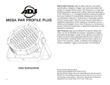
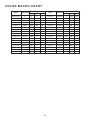
ADJ FLA650 Flat Par TW5 25W LED Flat Par Fixture
The ADJ FLA650 Flat Par TW5 25W LED Flat Par Fixture is a compact and powerful LED par fixture that is perfect for a variety of lighting applications. With its 25W LED engine, the FLA650 provides a bright and even output that is ideal for stage lighting, dance floors, and other entertainment applications. The fixture also features a built-in color mixing system that allows you to create a wide range of colors, including warm and cool whites.
In addition to its color mixing capabilities, the FLA650 also features a variety of built-in effects, including color chasing, strobe, and pulse effects. These effects can be controlled via DMX or the included infrared remote control, making it easy to create dynamic and eye-catching lighting displays.
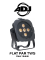
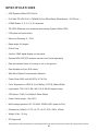


-
 1
1
-
 2
2
-
 3
3
-
 4
4
-
 5
5
-
 6
6
-
 7
7
-
 8
8
-
 9
9
-
 10
10
-
 11
11
-
 12
12
-
 13
13
-
 14
14
-
 15
15
-
 16
16
-
 17
17
-
 18
18
-
 19
19
-
 20
20
-
 21
21
-
 22
22
-
 23
23


ADJ FLA650 Flat Par TW5 25W LED Flat Par Fixture
The ADJ FLA650 Flat Par TW5 25W LED Flat Par Fixture is a compact and powerful LED par fixture that is perfect for a variety of lighting applications. With its 25W LED engine, the FLA650 provides a bright and even output that is ideal for stage lighting, dance floors, and other entertainment applications. The fixture also features a built-in color mixing system that allows you to create a wide range of colors, including warm and cool whites.
In addition to its color mixing capabilities, the FLA650 also features a variety of built-in effects, including color chasing, strobe, and pulse effects. These effects can be controlled via DMX or the included infrared remote control, making it easy to create dynamic and eye-catching lighting displays.
Ask a question and I''ll find the answer in the document
Finding information in a document is now easier with AI