
AXIS 207/207W/207MW Installation Guide Page 3
ENGLISH
AXIS 207/207W/207MW Network Camera
Installation Guide
This installation guide provides instructions for installing the AXIS 207/207W/207MW on
your network. For all other aspects of using the product, please see the product User’s Manual,
available on the CD included in this package, or from www.axis.com
Installation steps
Follow these steps to install the AXIS 207/207W/207MW on your local network (LAN):
1. Check the package contents against the list below.
2. Make all the necessary connections. See page 6.
3. Set an IP address. See page 6 for information on the available methods.
4. Set the password. See page 10.
5. For wireless models, configure the wireless connection. See page 11.
Package contents
Item Description
Axis Network Camera models AXIS 207
AXIS 207W
AXIS 207MW
Power adapter AXIS 207: Type PS-L, country-specific
AXIS 207W/AXIS 207MW: type PS-H, country-specific
Camera stand Supplied with 3 mounting screws. The extension section is ready fitted.
Flexible clamp For shelf mounting
Connector block 4-pin connector block for connecting external devices to the I/O terminal connector
Cable clip Self-adhesive - fixes to back panel for holding power cable
CD Axis Network Video Product CD, including installation tools and other software,
product documentation
Printed Materials AXIS 207/207W/207MW Installation Guide (this document)
Axis Warranty Document

Page 4 AXIS 207/207W/207MW Installation Guide
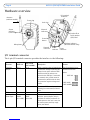
Hardware overview
I/O terminal connector
The 4-pin I/O terminal connector provides the interface to the following:
Function AXIS 207
AXIS 207W
AXIS 207MW Description Pinouts
Transistor
Output
Pin 4 Pin 4 With a maximum load of 100mA and
a maximum voltage of 24V DC, this
output has an open-collector NPN
transistor with the emitter con-
nected to the GND pin. If used with
an external relay, a diode must be
connected in parallel with the load,
for protection against voltage tran-
sients.
The I/O terminal pins are
numbered as shown
below.
Digital Input Pin 3 Pin 3 Connect to GND to activate, or leave
floating (or unconnected) to deacti-
vate.
GND Pin 2 Pin 1
Auxiliary DC
Power Input
Pin 1
(5VDC
min 2.5W)
Pin 2
(5VDC
min 3.5W)
Connected electrically in parallel
with the power adapter, this pin
provides an auxiliary connector for
mains power to the unit. It can also
be used to power auxiliary equip-
ment, max 50mA.
Focus ring
Status
indicator
(outer ring)
Microphone
Antenna
(wireless models)
Network
connector
Network
indicator
Control
button
Lock ring
Product ID &
serial number
(S/N) label
Wireless indicator
Power
indicator
I/O terminal
connector
Power
connector
(Wireless models only)
1
4
1
4
AXIS 207W
AXIS 207MW
AXIS 207

AXIS 207/207W/207MW Installation Guide Page 5
ENGLISH
LED indicators
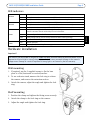
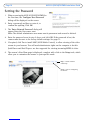
Hardware installation
Important!
Wall mounting
1. If required, use the 3 supplied screws to fix the base
plate to a flat (horizontal or vertical) surface.
2. To use a shorter stand, unscrew the lock ring to release
the camera, and remove the extension section.
3. Attach the camera, adjust the angle and tighten the lock
ring.
Shelf mounting
1. Position the clamp and tighten the fixing screw securely.
2. Attach the clamp to the lock ring on the camera.
3. Adjust the angle and tighten the lock ring.
Wireless Unlit Wired mode.
Green Steady for connection to a wireless network. Flashes for network activity.
Red Steady for no wireless network connection. Flashes when scanning for wireless networks.
Network
Amber Steady for connection to a 10 Mbit/s network. Flashes for network activity.
Green Steady for connection to a 100 Mbit/s network. Flashes for network activity.
Unlit No wired network connection, or AXIS 207W/AXIS 207MW in wireless mode.
Status
Green Steady for normal operation. Can be configured to flash green at intervals whenever the
camera is accessed. See the online help for more information.
Unlit When configured for “no flash” on camera access.
Amber Steady during startup, reset to factory default and when restoring settings.
Red Slow flash for failed upgrade.
Power Green Normal operation.
Amber Flashes green/amber during firmware upgrade.
The AXIS 207/207W/207MW is designed for indoor use only, and must always be positioned where it is not
exposed to direct sunlight or strong halogen light, which can cause permanent damage to the camera’s
image sensor. Damage as a result of exposure to strong light is not covered by the Axis warranty.

Page 6 AXIS 207/207W/207MW Installation Guide
Cable Connections
1. Using the self-adhesive strip, attach the supplied cable clip to the rear panel and fasten the
power cable to it. This will prevent accidental cable disconnection.
2. Connect the camera to the network using a standard network cable. For the wireless
models, this connection is temporary and allows the camera’s settings to be configured via
the wired network before connecting to the wireless network. If required, the AXIS 207W/
AXIS 207MW can be used solely as a wired camera, in which case the network cable
should be left connected.
3. Connect the power adapter to the camera.
Setting the IP address
The AXIS 207/207W/207MW must be assigned an IP address to make it accessible on the
network (wired or wireless). The installation information below applies to all models.
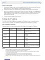
All installation methods
This table shows all of the available methods for setting or discovering the IP address.
Notes:
•UPnP™ and DHCP are both enabled by default in the AXIS 207/207W/207MW.
• The AXIS 207/207W/207MW has the default IP address 192.168.0.90
• To view the admin pages for the DHCP server, please see the server’s own documentation. You may need to
contact your network administrator.
• If setting the IP address fails, check that there is no firewall blocking the operation.
•The AXIS Dynamic DNS Service requires an Internet connection with no HTTP proxy.
•Bonjour - applies only to browsers that support this, e.g. Safari. Bonjour is a trademark of Apple Computer, Inc.
Operating system DHCP Server in
network
Install on same
network segment Installation method
Windows Optional Required AXIS IP Utility (recommended method for
Windows) See page 7
Mac OSX
(10.4 or later)
Optional Required Bonjour (recommended method for
Macintosh)
See page 8
Windows
(ME or XP)
Optional Required UPnP™
See page 8
All Required ARP/Ping
See page 8
All Recommended AXIS Dynamic DNS Service
See page 9
All Required View DHCP server admin pages for IP address
(See note below)

AXIS 207/207W/207MW Installation Guide Page 7
ENGLISH
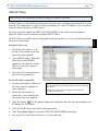
AXIS IP Utility
AXIS IP Utility is a free Windows application that discovers and displays Axis devices on your
network. The application can also be used to manually set a static IP address. Can be used on
networks with or without a DHCP server.
Note that you must install the AXIS 207/207W/207MW on the same network segment
(physical subnet) as the computer running AXIS IP Utility.
AXIS IP Utility is available on the CD supplied with this product, or it can be downloaded from
www.axis.com/techsup
Automatic discovery
1. Check that the camera is con-
nected to the network and that
power has been applied.
2. Start AXIS IP Utility. When the
AXIS 207/207W/207MW
appears in the window, double-
click it to open the camera’s
home page.
3. See page 10 for instructions on
how to set the password.
Set the IP address manually
1. Acquire an unused IP address on
the same network segment as
your computer.
2. Check that the camera is
connected to the network and
that power has been applied.
3. Click the button (Set IP address using serial number) and enter the serial number and
IP address for the camera.
4. Click the Set IP button and follow the instructions.
5. Click View Home Page to access the AXIS 207/207W/207MW web pages.
6. See page 10 for instructions on how to set the password.
AXIS IP Utility is the recommended method for setting an IP address in Windows.
Notes:
Set the IP address using IP Utility within 2 minutes of starting
the camera.
AXIS IP Utility can be used to change a dynamically set
IP address to a static one.

Page 8 AXIS 207/207W/207MW Installation Guide
Bonjour™
Bonjour™ will automatically discover the AXIS 207/207W/207MW when it is connected to the
network. Simply navigate to the Bonjour™ bookmark in your browser (e.g. Safari) and click on
the camera link to access the web pages. See page 10 for instructions on how to set the
password.
UPnP™
UPnP™ functionality is enabled by default in the AXIS 207/207W/207MW. If also enabled on
your computer (Windows ME or XP), the camera will automatically be detected and a new icon
will be added to “My Network Places.” Click this icon to access the camera.
See page 10 for instructions on how to set the password.
Installation with ARP/Ping
1. Acquire an unused IP address on the same network segment as your computer is connected
to.
2. Locate the serial number (S/N) on the rear label (see page 3).
3. Open a command prompt on your computer. As appropriate for your operating system,
enter the following commands:
4. Check that the network cable is connected. Start/restart the camera by disconnecting and
reconnecting power.
5. Close the Command prompt when you see ‘Reply from 192.168.0.125: ...’ or similar.
6. Start your browser, type in http://<IP address> in the Location/Address field and press
Enter on your keyboard.
7. See page 10 for instructions on how to set the password.
Windows syntax:Windows example:
arp -s <IP Address> <Serial Number>
ping -l 408 -t <IP Address>
arp -s 192.168.0.125 00-40-8c-18-10-00
ping -l 408 -t 192.168.0.125
UNIX/Linux/Mac syntax:UNIX/Linux/Mac example:
arp -s <IP Address> <Serial Number> temp
ping -s 408 <IP Address>
arp -s 192.168.0.125 00:40:8c:18:10:00 temp
ping -s 408 192.168.0.125
Note:
To install the UPnP™ service on your computer, open the Control Panel from the Start Menu and select
Add/Remove Programs. Select Add/Remove Windows Components and then Networking Services. Click
Details and then select UPnP to add it.
UPnP™ is a certification mark of the UPnP™ Implementers Corporation.

AXIS 207/207W/207MW Installation Guide Page 9
ENGLISH
Notes:
• To open a command prompt in Windows: from the Start menu, select Run... and type cmd
(or command in Windows 98/ME). Click OK.
• To use the ARP command on a Mac OS X, use the Terminal utility, which is found under Applications > Utilities
• Set the IP address within 2 minutes of starting the camera.
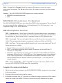
AXIS Internet Dynamic DNS Service
The AXIS Internet Dynamic DNS Service is a free service provided by Axis, which allows you
to quickly and simply install your camera, which then receives a static DNS name. More
information about the AXIS Internet Dynamic DNS Service is available at www.axiscam.net
To perform this procedure, your network should have an Internet connection with no HTTP
proxy, and IP addresses should preferably be assigned via DHCP.
Follow these instructions:
1. After making the connections for network and power, wait for the Status indicator to show
a steady green.
2. Press the Control button once. The Status indicator flashes green while it connects to the
AXIS Internet Dynamic DNS Service.
3. Wait for the Status indicator to go back to showing a steady green.
4. To complete the installation, now visit www.axiscam.net from an Internet connected
computer. This must be done within 60 minutes of pressing the Control button.
5. Follow the on-screen instructions provided by the AXIS Internet Dynamic DNS Service.
You will need the product’s serial number to complete the installation. See page 3.
See page 10 for instructions on how to set the password.
Important!
To remove the DNS name and unregister from this service, open the Setup pages in the AXIS
207/207W/207MW, click System Options > Network > TCP/IP > Basic, click the Settings
button for the AXIS Internet Dynamic DNS Service and finally, click the Remove button.
Please note that this procedure will send the IP address, firmware version, product type and serial number
of the AXIS 207/207W/207MW to the AXIS Internet Dynamic DNS Service. No personal information is
transferred.

Page 10 AXIS 207/207W/207MW Installation Guide
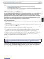
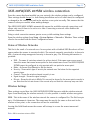
Setting the Password
1. When accessing the AXIS 207/207W/207MW for
the first time, the ‘Configure Root Password’
dialog will be displayed on the screen.
2. Enter a password and then re-enter it, to
confirm the spelling. Click OK.
3. The ‘Enter Network Password’ dialog will
appear. Enter the User name: root
Note: The default administrator user name root is permanent and cannot be deleted.
4. Enter the password as set in step 2 above, and click OK. If the password is lost, the
camera must be reset to the factory default settings. See page 13.
5. If required, click Yes to install AMC (AXIS Media Control), to allow viewing of the video
stream in your browser. You will need administrator rights on the computer to do this.
QuickTimeTM and Real PlayerTM are also supported for viewing streaming MPEG-4 video.
6. The camera’s Live View page is displayed, complete with a link to the Setup tools, which
allow you to customize the camera to your specific needs.
Setup - tools for configuring
the camera.
Help - context-sensitive
online help.

AXIS 207/207W/207MW Installation Guide Page 11
ENGLISH
AXIS 207W/AXIS 207MW wireless connection
Once the camera has been installed on your network, the wireless settings can be configured.
These settings should always (i.e. both during installation and at all other times) be configured
or changed in the camera first and in the wireless access point secondly. This ensures that the
camera is always accessible when making changes.
The AXIS 207W/AXIS 207MW automatically senses the available network connections, and
allows only one of these to be active at a time. Connecting a network cable disables the
wireless connection.
Using a wired connection ensures greater secrecy while making these settings.
Open the wireless settings from Setup > System Options > Network > Wireless. These settings
can also be reached from the Basic Configuration menu.
Status of Wireless Networks
This list is the result of a network scan. Access points with a disabled SSID Broadcast will not
appear unless the camera is associated with it. The network currently associated to is shown in
blue. A network using unsupported security is shown in grey. The following information is
provided:
• SSID - The name of a wireless network (or ad-hoc device). If the same name occurs several
times this means that several access points for that network were found. The AXIS 207W/AXIS
207MW cannot be configured to only associate with one particular access point.
• Mode - An Access Point (Master) or Ad-Hoc device.
• Security - Shows which type of security the network uses. See below for the supported
security types.
• Channel - Shows the wireless channel currently in use.
• Signal strength - Shows the signal strength.
• Bit rate - Shows the bit rate in Mbit/s. This can only be shown for the access point currently in
use. Note that the bit rate shown is the current rate, and that this value may vary over time.
Wireless Settings
These settings control how the AXIS 207W/AXIS 207MW interacts with the wireless network.
Apart from identifying the wireless network, it is also possible to enable wireless encryption.
SSID - This is the name of the wireless network the camera is configured for. The field accepts
up to 32 alphanumeric characters. The name must be exactly the same as that used in the
wireless access point, or the connection will not be established.
Leaving this field blank means the camera will attempt to access the nearest unsecured
network.
Note: SSID is sometimes written as ESSID.

Page 12 AXIS 207/207W/207MW Installation Guide
Mode - Setting this to Managed means the camera will attempt to access the nearest
unencrypted access point. The Ad-hoc option allows the camera to connect to other wireless
devices.
Security - The AXIS 207W/AXIS 207MW supports two security methods:
•WPA-PSK (recommended method)
•WEP
WPA-PSK (Wi-Fi Protected Access - Pre-Shared Key)
The AXIS 207W/AXIS 207MW uses a pre-shared key (PSK) for key management. The pre-shared
key can be entered either as Manual hex, as 64 hexadecimal (0-9, A-F) characters, or as a
Passphrase, using 8 to 63 ASCII characters.
WEP (Wired Equivalent Protection)
WEP - Authentication - Select Open or Shared Key System Authentication, depending on
the method used by your access point. Not all access points have this option, in which case
they probably use Open System, which is sometimes known as SSID Authentication.
WEP - Key length - This sets the length of the key used for the wireless encryption, 64 or
128 bit. The encryption key length can sometimes be shown as 40/64 and 104/128.
WEP - Key Type - The key types available depend on the access point being used. The fol-
lowing options are available:
• Manual - Allows you to manually enter the hex key.
• ASCII - In this method the string must be exactly 5 characters for 64-bit WEP and 13
characters for 128-bit WEP.
• Passphrase - The passphrase can contain up to 31 characters. In 64-bit WEP, the Passphrase
generates 4 different keys. For 128-bit WEP, only 1 key is generated, which is then replicated
for all 4 keys. Key generation is not standardized and can differ from brand to brand. Check
that the generated keys are identical to those in your access point - if not, they must be
entered manually.
WEP - Active Transmit Key - When using WEP encryption, this selects which of the 4
keys the AXIS 207W/AXIS 207MW uses when transmitting.
Complete the wireless installation
1. Check that the wireless settings in the AXIS 207W/AXIS 207MW correspond to the settings
in the access point.
2. Disconnect the network cable from the camera.
3. Refresh the web page after 20-30 seconds to confirm the wireless connection. If the camera
cannot be accessed, run AXIS IP Utility to discover the new IP address and try again.

AXIS 207/207W/207MW Installation Guide Page 13
ENGLISH
Accessing the camera from the Internet
Once installed, your camera is accessible on your local network (LAN). To access the camera
from the Internet you must configure your broadband router to allow incoming data traffic to
the camera. One method for this is NAT traversal via port mapping.
For more information, please refer to the product’s User’s Manual, available on the CD
included in this package and from the Axis Web site at http://www.axis.com.
See also the AXIS Internet Dynamic DNS Service at www.axiscam.net
Resetting to the Factory Default Settings
This will reset all parameters, including the IP address, to the Factory Default settings:
1. Disconnect power to the camera.
2. Press and hold the Control button and reconnect power.
3. Keep the button pressed until the Status Indicator displays yellow (this may take up to 15
seconds), then release the button.
4. When the Status indicator displays green (which can take up to 1 minute) the
camera is reset to the factory default settings.
5. Re-install the camera using one of the methods described in this document.
More information
For more information, please see the product’s User’s Manual, which is available on the CD
included in this package. Updated versions can be obtained from www.axis.com

-
 1
1
-
 2
2
-
 3
3
-
 4
4
-
 5
5
-
 6
6
-
 7
7
-
 8
8
-
 9
9
-
 10
10
-
 11
11
-
 12
12


Axis Communications AB PNBAXIS207MW User manual
- Category
- Security cameras
- Type
- User manual
Ask a question and I''ll find the answer in the document
Finding information in a document is now easier with AI
Related papers
Other documents
-
Axis 207w network camera User manual
-
Axis 0264-006 User manual
-
Axis AXIS 207MW User manual
-
Axis Communications 207W User manual
-
-
-
Axis Communications 31922 User manual
-
QNAP 540105G0101P Datasheet
-
-