Page is loading ...

DRAFT COPY
© 2018 HeathCo LLC 209819-01A
INSTALLATION AND OPERATING
INSTRUCTIONS
SAFETY INFORMATION ......................................2
PREPARATION ...............................................2
HARDWARE CONTENTS ......................................2
LIGHT FIXTURE INSTALLATION ...............................3
WIRING THE LIGHT FIXTURE .................................3
MOUNTING THE LIGHT FIXTURE .............................4
TESTING AND ADJUSTMENTS ................................5
LINKING LIGHTS .............................................5
FINAL SETUP ................................................6
LINK TECHNOLOGY ..........................................6
OPERATING MODES .........................................6
CARE AND MAINTENANCE ...................................7
BULB REPLACEMENT ........................................7
TROUBLESHOOTING GUIDE ..................................8
SPECIFICATIONS .............................................9
TECHNICAL SERVICE .........................................9
THREE YEAR LIMITED WARRANTY .......................... 10
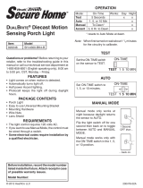
DualBrite® Motion Sensing
Decorative Light
Model 4700
Motion Decorative Light Questions?
Please refer to the troubleshooting guide in this manual
or call our technical service department (English speak-
ing only) at 1-800-858-8501, 8:00 a.m. - 5:00 p.m., CST,
Monday - Friday before returning to your retailer.
Keep this manual for future reference.
ATTACH YOUR RECEIPT HERE
Receipt is required for all warranty requests.
Purchase Date
For a description of the DualBrite® technology, see page 6.

2209819-01
SAFETY INFORMATION
Please read and understand this entire manual before at-
tempting to assemble, operate, or install the product.
is light xture requires 120-volts AC. All wiring must be
in accordance with the National Electrical Code (Canadian
Electrical Code in Canada). Some local electrical codes
require installation by a qualied electrician.
WARNING
• Turn power o at circuit breaker or fuse when
wiring xture. Place tape over circuit breaker
switch and verify power is o at the xture.
CAUTION
• Do not cut any wires that have factory installed
wire connectors or remove the wire connectors.
PREPARATION
Before beginning installation of product, make sure all parts
are present. Compare parts with hardware contents list. If
any part is missing or damaged, do not attempt to assemble,
install, or operate the product.
Tools Required for Assembly (not included): Phillips and
athead screwdrivers, pliers, wire strippers/cutters, multi-
meter, electrical tape, silicone sealant, safety glasses, work
gloves, and ladder
• For easy installation and to operate the light using Manual
mode, replace an existing light xture operated by a wall
switch.
• Do not connect to dimmers or timers.
• For best performance, mount xture about 6 feet (1.8 m)
above the ground.
Estimated Installation Time: 30 minutes
3x – Wire Connectors
2x – Mounting
Bracket Screw
1x – Mounting Bracket
2x – Fixture Mounting Screws
2x – Decorative Nut
(This assembly is attached
to the rear of the lantern
canopy.)
HARDWARE CONTENTS
Note: Illustrations may vary from actual unit.
GND

3209819-01
Mounting
Bracket
Mounting
Bracket
LIGHT FIXTURE INSTALLATION
For best performance, mount the xture about 6 feet (1.8m)
above the ground.
1. Remove two decorative nuts.
2. Remove mounting bracket.
3. Tighten mounting screws nger tight.
4. Attach mounting bracket to junction box.
Decorative Nut
Mounting Screw
Note: We recommend having an assistant help hold the
lantern assembly during the wiring process.
GND
Ground Screw
Bracket
Mounting
Screws
Junction
Box
WIRING THE LIGHT FIXTURE
Note: All wiring must be run in accordance with the Na-
tional Electrical Code through conduit or another accept-
able means. Contact a qualied electrician if there is any
question as to the suitability of the system.
WARNING: Turn power o at circuit breaker
or fuse.
One Motion Light
Two Motion Lights
Black
White
Green
or Bare
Copper
Green
or Bare
Copper
Light
Fixture
Black
White
Light
Fixture
Light
Fixture

4209819-01
Black to black
White to white
Recommended Grounding Method
Use a green ground “pigtail” (not provided) and twist
one end together with the bare xture wire and the box
ground wire. Secure with a wire connector. Secure the
other end of the “pigtail” with the GND screw on the
mounting plate.
Connect the xture wires to the wires in the junction box.
Twist the wires together and secure with wire connectors.
If you have metal junction box, you may not need the green
“pigtail”. If you are unsure about the grounding method,
consult your local building code.
Junction
Box
MOUNTING THE LIGHT FIXTURE
1. Make sure wire connectors and wires are inside the
junction box.
2. Slide the xture assembly onto the mounting screws.
Tighten decorative nuts removed in step 1 of
Light
Fixture Installation
section securely against xture base.
Mounting Screw
Decorative Nut
3. Install one medium base light bulb (100 Watt maximum,
tungsten incandescent). See
Bulb Replacement
section for
bulb installation.
4. Caulk around xture base with silicone weather sealant.
Caulking Around Fixture Base

5209819-01
Maximum Range Maximum
Coverage Angle
(Top View)
Sensor Controls
– +
SENS
DUALBRITECHANNEL
OFF A B C OFF TEST 4H D2D
30 ft. (9.1 m)
6 ft.
(1.8 m)
150°
LINKING LIGHTS
is light has been designed with Link technology which
allows multiple lights to be connected together wirelessly.
Linked lights can be grouped into one of three possible
channels to create linked zones of lighting. See
Link Tech-
nology
section for more information.
1. Slide the CHANNEL switch to the desired channel
(A, B, or C) on all lights to be linked together.
2. Slide the DUALBRITE switch to the TEST position
on all of the selected lights. Note: e TEST mode
overrides the photocell (daylight shuto feature) and
allows the light xture to be tested day or night.
3. Walk in front of each light to ensure all linked lights
are activated from another linked light. Note: e linked
lights may not come on at the same time because of the
delay of the transmission signal.
Rotating Sensor Head to Change Coverage Area
1
5
0
°
1
5
0
°
TESTING AND ADJUSTMENTS
e TEST mode overrides the photocell (daylight shuto
feature) and allows the light xture to be tested day or night
when the DUALBRITE switch is in the TEST position. e
light will stay on for 5 seconds after all motion has stopped.
1. Slide the CHANNEL switch to OFF.
2. Slide the DUALBRITE switch to TEST.
3. Set sensitivity control (SENS) to MIN position.
4. Turn on the circuit breaker or fuse and the light switch.
5. Allow the sensor to completely warm up (90 seconds)
before beginning the setup process.
6. Perform a walk test. Walk through the coverage area
noting where you are when the lights turn on.
7.
Stop, wait for the light to turn o (5 seconds), and then
begin walking again. Continue this process until the
detection zone has been established.
8.
Move the sensor head left or right to change the coverage
area. Note: Grasp the sensor only as shown and turn
the entire sensor. Any other method may damage
the sensor. Do not force it past the stops.
9. Adjust the sensitivity (SENS) to increase or decrease
the range as needed. Too much sensitivity may cause
false triggering due to heat sources in the coverage area
(see
Testing and Adjustments
or
Troubleshooting
section).

6209819-01
Note: When rst turned on wait about 1 1/2 minutes for
the circuitry to calibrate.
* resets to Auto Mode at dawn.
Mode: On-Time Works: Day Night
Test 5 Seconds x x
Auto 5 Minutes x
Accent O, 4 Hours, Dusk-to-
Dawn x
Manual 6 Hours or Dawn* x
FINAL SETUP
1. When testing is complete, set the DUALBRITE switch
to the desired amount of time after dusk the lights should
remain on at a reduced light level [O, 4 Hrs., Dusk-to-
Dawn (D2D)]. See
Optional DualBrite® Control
section
for more information.
2. e amount of time the lights stay on at full bright after
ALL
motion has stopped in front of
ALL
linked lights
is preset to 5 minutes.
LINK TECHNOLOGY
Link technology allows multiple lights to be connected
together wirelessly. When one light senses motion it will
turn on full bright and send out a wireless signal. All lights
within range and on the same channel will also turn on full
bright. Each time a light receives a signal, it will then repeat
the signal so other lights not in range of the rst light will
also turn on full bright. Linked lights can be grouped into
one of three possible channels (A, B, or C) to create linked
zones of lighting. Note: Linked lights turn o independently
of each other and may not turn o at exactly the same time.
Illustration example:
Light #1 senses motion and sends a
signal. Light #2 is out of range of light #1 and does not
receive the signal. Light #3 is in range of light #1 and receives
the activation signal. Light #3 is activated and repeats the
signal. Light #2 is in range of light #3 and is activated. Note:
All the lights will send out a signal when activated, even if
the light’s DualBrite switch is set to OFF. If the light is in
manual mode, it will repeat any signal it receives but will
not initiate a signal.
OPERATING MODES
1
2
3
• Motion Sensor (AUTO) – is light xture is designed
to automatically turn on when the sensor detects a tem-
perature dierence moving across the front of the motion
sensor. e amount of time the lights stay on at full bright
after
ALL
motion has stopped in front of
ALL
linked lights
is preset to 5 minutes.
• Optional DualBrite® Control – DualBrite mode is
a selectable feature that turns the light on at dusk in a
reduced light level. e light will stay on at the reduced
light level for the amount of time selected [O, 4 hr.,
dusk-to-dawn (D2D)]. When motion is detected, the light
will increase to full bright. e light will stay on at the full
bright level for 5 minutes after
ALL
motion has stopped
in front of
ALL
linked lights. e light will then return
to the reduced light level. Once the DualBrite timer runs
out, the light will turn ON only when motion is detected
by any of the linked lights. Selecting OFF disables the
DualBrite feature, however the motion sensing and Link
features will continue to work.
For linked lights, the rst light to sense darkness will
turn on all other linked lights on the same channel if the
DualBrite timer has been turned ON on each linked light.
e lights will turn OFF independently of each other and
may not turn OFF at exactly the same time.

7209819-01
CARE AND MAINTENANCE
• To prolong the original appearance, clean with clear water
and a soft damp cloth only.
• Do not use paints, solvents, or other chemicals on this
light xture. ey could cause a premature deterioration
of the nish. is is not a defect in the nish and will not
be covered by the warranty.
• Do not spray with hose or power washer.
BULB REPLACEMENT
1. While holding the globe assembly with one hand,
remove the two decorative screws on top of xture cap
with the other.
2. Replace bulb (tungsten incandescent, medium base,
type “A”, 100 watt maximum).
4. Replace globe assembly onto xture.
5. Secure with decorative screws.
• Manual Mode – Manual mode overrides the motion sen-
sor and “DUALBRITE” control so the light will operate
full bright. is feature only works at night and only for
one night at a time. e motion sensor will reset to motion
sensing mode after 6 hours or sunrise, whichever comes
rst. Manual mode can be toggled on and o using a wall
switch. Note: If the power to the light xture is o for
more than 5 seconds, allow the motion sensor to warm
up prior to switching to manual mode.
1. Ensure the power to the light is ON and the sensor
has warmed up (90 seconds).
2. To turn manual mode on after dark, switch the power
OFF–ON–OFF–ON at the wall switch within 5 sec-
onds.
3. To turn manual mode o, switch the power OFF–ON–
OFF–ON at the wall switch within 5 seconds.
OFF OFFON ON
Less than 5 seconds
IMPORTANT: If manual mode does not turn ON or OFF,
use a slower pace turning the power ON and OFF at the
wall switch while staying within 5 seconds.
Decorative Screw
Fixture Cap
Globe
Assembly

8209819-01
TROUBLESHOOTING GUIDE
SYMPTOM POSSIBLE CAUSE SOLUTION
Lights will not
come on. 1. Light switch is turned o.
2. Fuse is blown or circuit breaker is turned o.
3. Daylight turn-o is in eect.
4. Sensor not detecting movement.
5. Incorrect circuit wiring, if this is a new installation.
6. e outside air temperature is close to the same as a
person’s body heat.
1. Turn light switch on.
2. Replace fuse or turn circuit breaker on.
3. Recheck after dark.
4. Re-aim the sensor to cover desired area.
5. Verify wiring is correct.
6. Increase the “Sensitivity” setting.
Lights come on in
daylight. 1. e motion sensor may be installed in a relatively dark
location.
2. e “DUALBRITE” switch is in the “TEST” position.
1. e xture is operating normally under these conditions.
2. Set the “DUALBRITE” switch to the OFF, 4 hour, or dusk-
to-dawn (D2D) setting.
Lights come on for no
apparent reason. 1. e motion sensor may be sensing small animals or
automobile trac.
2. Sensitivity is set too high.
3. e “DUALBRITE” switch is in the 4 hour or dusk-to-
dawn (D2D) setting.
4. e light xture is linked to another light.
5. e light xture is on the same channel as a neighbor’s
linked light xture.
6. e outside temperature is much warmer or cooler than
a person’s body heat (summer or winter).
7. e light xture is wired through a dimmer or timer.
1. Re-aim sensor. Reduce sensitivity.
2. Reduce sensitivity.
3. e light xture is operating normally under these circumstances.
4. e light xture is operating normally if linked. e Link option
can be turned OFF or set to a dierent channel.
5. Change the channel of the aected light xtures to a dierent
channel.
6. Reduce sensitivity.
7. Do not use a dimmer or timer to control the light xture. Replace
the dimmer or timer with a standard on/o wall switch.
e lights turn o too
late in dusk-to-dawn
(D2D) setting.
e light xture may be installed in a relatively dark location. Relocate the light xture or use the 4 hour setting.
Link technology lights
are not activating each
other.
1. Linked lights are not set to the same channel.
2. Too many obstructions are creating interference between
the linked lights.
1. Ensure the linked lights are set to the same channel.
2a. Add a Link light between the existing lights to create an
additional relay point.
2b. Move the Link lights closer to each other.
Lights stay on
continuously. 1. e sensor may be picking up a heat source like an air
vent, dryer vent, or brightly painted, heat-reective surface.
2. e motion sensor is in manual mode.
3. Light control is in DB® mode.
4. Sensitivity is set too high.
5. A linked light xture is picking up continuous motion
and is keeping all linked lights on.
6. Motion is being detected by multiple linked lights and
is keeping all linked lights on.
7. e light xture is wired through a dimmer or timer.
8. e light xture is on the same circuit as a motor,
transformer, or uorescent bulb.
1. Re-aim sensor. Reduce sensitivity.
2. Switch the motion sensor to auto. See
Manual mode
on page 7.
3. Slide DB® switch to OFF position.
4. Reduce sensitivity.
5. e light xtures are operating normally under these circum-
stances.
6. e light xtures are operating normally under these circum-
stances.
7. Do not use a dimmer or timer to control the light xture. Replace
the dimmer or timer with a standard on/o wall switch.
8. Install the light xture on a circuit without motors, transformers,
or uorescent bulbs.
Lights ash on
and o. 1. Light control is in the TEST mode and warming up.
2. Heat being reected from other objects may be aecting
the sensor.
1. While in “TEST” mode, the light only stays on for 5 seconds.
Set the “DUALBRITE” switch to OFF, 4 hour, or dusk-to-
dawn (D2D).
2. Re-aim sensor. Reduce sensitivity.
Seasonal Temperature Changes – e closer the surrounding temperature is to a person’s body heat, the less sensitive the sensor will appear. e greater
the temperature dierence, the more sensitive the sensor will appear. e SENS control might need to be readjusted toward MIN or MAX as the outside
temperature changes for the dierent seasons. is is a normal part of the light sensor’s operation.

9209819-01
SPECIFICATIONS
Range ................................................................Up to 30 ft. (9.1 m) [varies with surrounding temperature]
Sensing Angle....................................................Up to 150°
Sensor Aiming Adjustment Angle ....................90°
Electrical Load ..................................................Up to 100 Watt Maximum Incandescent
Bulb Type ..........................................................Medium Base, Type “A”, 100 Watt Maximum
Power Requirements ..........................................120 VAC, 60 Hz
Operating Modes ..............................................TEST, MOTION ACTIVATED, and MANUAL MODE
ON-Timer ......................................................... 5 minutes (non-adjustable)
DB® Timer ..........................................O, 4 hours, dusk-to dawn (D2D)
Test Timer ......................................................... 5 Seconds
Manual Mode Timer ......................................... Maximum 6 Hours
Link Technology Range ....................................Up to 100 ft (30.5 m) between each Link light xture [varies with sur-
rounding obstructions].
TECHNICAL SERVICE
Please call 1-800-858-8501 (English speaking only) for assistance
before returning product to store.
If you experience a problem, follow this guide. You may also want to visit our Web site at: www.hzsupport.com. If the
problem persists, call* for assistance at 1-800-858-8501 (English speaking only), 8:00 AM to 5:00 PM CST (M-F).
You may also write* to:
HeathCo LLC
P.O. Box 90045
Bowling Green, KY 42102-9045
ATTN: Technical Service
* If contacting Technical Service, please have the following information available: Model Number, Date of Purchase,
and Place of Purchase.
No Service Parts Available for this Product
Please keep your dated sales receipt, it is required for all warranty requests.

10 209819-01
THREE YEAR LIMITED WARRANTY
is is a “Limited Warranty” which gives you specic legal rights. You may also have other rights which vary from state to state
or province to province.
For a period of three years from the date of purchase, any malfunction caused by factory defective parts or workmanship will be
corrected at no charge to you.
Not Covered - Repair service, adjustment and calibration due to misuse, abuse or negligence, light bulbs, batteries, and other
expendable items are not covered by this warranty. Any damage to the light xture resulting from the use of chemicals or a pres-
sure washer machine are not covered by this warranty. Unauthorized service or modication of the product or of any furnished
component will void this warranty in its entirety. is warranty does not include reimbursement for inconvenience, installation,
setup time, loss of use, unauthorized service, or return shipping charges.
Finish Warranty Exclusions - Finishes for xtures installed outdoors are subject to change due to prolonged exposure to sunlight,
pollutants, and other environmental conditions. Metal nishes will naturally mature over time, changing in appearance and creating
a living nish. Painted nishes on outdoor xtures may naturally fade over time, depending on the xture’s exposure to the outdoor
elements. us, any claim for fading, discoloration, or “patina” of a nish on an outdoor xture is not applicable to the above war-
ranty. See “Care and Maintenance”, page 7, for proper cleaning of the xture.
is warranty covers only HeathCo LLC assembled products and is not extended to other equipment and components that a
customer uses in conjunction with our products.
THIS WARRANTY IS EXPRESSLY IN LIEU OF ALL OTHER WARRANTIES, EXPRESS OR IMPLIED, INCLUDING
ANY WARRANTY, REPRESENTATION OR CONDITION OF MERCHANT ABILITY OR THAT THE PRODUCTS
ARE FIT FOR ANY PARTICULAR PURPOSE OR USE, AND SPECIFICALLY IN LIEU OF ALL SPECIAL, INDIRECT,
INCIDENTAL, OR CONSEQUENTIAL DAMAGES.
REPAIR OR REPLACEMENT SHALL BE THE SOLE REMEDY OF THE CUSTOMER AND THERE SHALL
BE NO LIABILITY ON THE PART OF HEATHCO LLC FOR ANY SPECIAL, INDIRECT, INCIDENTAL, OR
CONSEQUENTIAL DAMAGES, INCLUDING BUT NOT LIMITED TO ANY LOSS OF BUSINESS OR PROFITS,
WHETHER OR NOT FORESEEABLE. Some states or provinces do not allow the exclusion or limitation of incidental or
consequential damages, so the above limitation or exclusion may not apply to you.
Please keep your dated sales receipt, it is required for all warranty requests.
HeathCo LLC reserves the right to discontinue products and to change specications at any time without incurring any
obligation to incorporate new features in products previously sold.
is device complies with Part 15 of the FCC Rules. Operation is subject to the following two conditions: (1) this device
may not cause harmful interference, and (2) this device must accept any interference received, including interference
that may cause undesired operation.
CAN ICES-005 (B)/NMB-005 (B)
Warning: Changes or modications to this unit not expressly approved by the party responsible for compliance could
void the user's authority to operate the equipment.
Note: is equipment has been tested and found to comply with the limits for aClass B digital device, pursuant to
part 15 of the FCC Rules. ese limits are designed to provide reasonable protection againstharmful interferencein a
residential installation. is equipment generates, uses and can radiateradio frequency energyand, if not installed and
used in accordance with the instructions, may causeharmful interferenceto radio communications. However, there is no
guarantee that interference will not occur in a particular installation. If this equipment does causeharmful interferenceto
radio or television reception, which can be determined by turning the equipment o and on, the user is encouraged to
try to correct the interference by one or more of the following measures:
- Reorient or relocate the receiving antenna.
- Increase the separation between the equipment and receiver.
- Connect the equipment into an outlet on a circuit dierent from that to which the receiver is connected.
- Consult the dealer or an experienced radio/TV technician for help.

11209819-01
INSTRUCCIONES PARA SU INSTALACIÓN
Y FUNCIONAMIENTO
INFORMACIÓN SOBRE LA SEGURIDAD .....................12
PREPARACIÓN ............................................. 12
FERRETERÍA OFRECIDA .................................... 12
INSTALACIÓN DEL APARATO DE LUZ ....................... 13
CABLEADO DEL APARATO DE LUZ .........................13
MONTAJE DEL APARATO DE LUZ ........................... 14
PRUEBAS Y AJUSTES ....................................... 15
LUCES DE INTERCONEXIÓN ................................ 15
CONFIGURACIÓN FINAL ...................................16
TECNOLOGÍA LINK .........................................16
MODALIDADES DE OPERACIÓN ........................... 16
CUIDADO Y MANTENIMIENTO .............................17
REEMPLAZO DE LA BOMBILLA .............................17
GUÍA DE INVESTIGACIÓN DE AVERÍAS .....................18
ESPECIFICACIONES ........................................19
SERVICIO TÉCNICO ........................................ 19
GARANTÍA LIMITADA A 3 AÑOS ............................20
Para una descripción de la tecnología DualBrite ®, vea la página 16.
¿Preguntas?
Por favor, consulte la guía de solución de
problemas en este manual o llame a nuestro de-
partamento de servicio técnico (solo para Inglés) al
1-800-858-8501, de 8:00 am - 5:00 pm, hora central,
de lunes a viernes antes de volverlo a la tienda.
Guarde este manual para referencia en el futuro.
ADJUNTE SU RECIBO AQUÍ
Se requiere recibo para todas las solicitudes de
garantía.
Fecha de compra
© 2018 HeathCo LLC 209819-01 S
Luz decorativa detectora de
movimiento DualBrite®
Modelo 4700
Luz decorativa detectora de movimiento

12 209819-01
INFORMACIÓN SOBRE LA
SEGURIDAD
Por favor lea y comprenda todo el manual antes de intentar
ensamblar, operar o instalar el producto.
Esta lámpara requiere de 120 voltios CA. Todo el cableado
debe ser de acuerdo con el Código Nacional de Electricidad
(Código Eléctrico Canadiense en Canadá). Algunos códigos
eléctricos locales requieren que la instalación sea hecha por
un electricista calicado.
ADVERTENCIA
• Desconecte la alimentación en el disyuntor o
fusible cuando haga el cableado de la lámpara.
Ponga cinta adhesiva sobre el interruptor del
disyuntor y verique que la electricidad esté
apagada en la lámpara.
PRECAUCIÓN
• No corte ningún cable que tenga conectores
de cables instalados en fábrica ni retire los
conectores.
PREPARACIÓN
Antes de comenzar la instalación, asegúrese de que tiene
todas las piezas. Compare las piezas con la lista de ferretería
ofrecida. Si alguna pieza falta o está dañada, no intente
ensamblar, instalar o utilizar el producto.
Herramientas necesarias para el montaje (no incluidas):
Destornilladores Phillips y de cabeza plana, pinzas, sepa-
radores / cortadoras de alambre, multímetro, cinta aislante,
sellador de silicona, gafas de seguridad, guantes de trabajo
y escalera.
• Para una instalación fácil y para operar la luz utilizando
la modalidad Manual, cambie el aparato de luz existente
que funciona con un interruptor de pared.
• No lo conecte a atenuadores o temporizadores.
• Para un mejor funcionamiento, monte la unidad cerca de
6 pies (1,8 m) por encima del suelo.
Tiempo estimado de instalación: 30 minutos
3x – Conectores de alambre
2x – Tornillo del
soporte de montaje
FERRETERÍA OFRECIDA
Nota: Las ilustraciones pueden ser diferentes de la unidad
comprada.
1x – Soporte de montaje
2x – Tornillos de montaje
del aparato
2x – Tuerca decorativa
(Este conjunto está sujeto
a la parte trasera del farol)
GND

13209819-01
GND
ADVERTENCIA: Desconecte la alimentación en
el disyuntor o en el fusible.
Nota: Todo el cableado debe realizarse de acuerdo con el
Código Eléctrico Nacional usando tubería o algún otro
medio aceptable. Póngase en contacto con un electricista
calicado si tiene alguna pregunta referente a la aptitud
del sistema.
Luz de un movimiento
Luz de dos movimientos
Negro
Negro
Blanco
Blanco
Verde o
desnudo
Verde o
desnudo
Artefacto
de luz
Artefacto
de luz Artefacto
de luz
INSTALACIÓN DEL APARATO DE LUZ
Para un mejor funcionamiento, instale el aparato a casi
1.8 m del suelo.
1. Quite dos tuercas decorativas.
2. Retire el soporte de montaje.
3. Ajuste lo más que pueda los tornillos para montaje con
sus dedos.
4. Sujete el soporte de montaje a la caja de empalme.
Nota: Recomendamos tener un asistente que ayude a sos-
tener el conjunto del farol durante el proceso de cableado.
CABLEADO DEL APARATO DE LUZ
Soporte de
montaje
Tuerca decorativa
Tornillo de montaje
Tornillos del
tierra
Tornillo de
montaje del
soporte
La caja de
empalme
Soporte de
montaje

14 209819-01
Método recomendado de conexión a tierra
Use un “cable exible” verde de tierra (no provisto) y
tuerza un extremo con el cable desnudo del aparato y con
el cable de a tierra de la caja. Asegúrelos con un conector
de cables. Asegure el otro extremo del “cable exible” con
el tornillo de a tierra de la placa de montaje.
Conecte los alambres del aparato a los alambres de la caja
de empalme. Tuerza juntos los alambres y asegúrelos con
conectores de alambre.
Si tiene una caja de empalme de metal, no necesita el “cable
exible”. Si no está seguro del método de conexión a tierra,
consulte con el código local de construcción.
Negro a negro
Blanco a
blanco
MONTAJE DEL APARATO DE LUZ
1. Asegúrese que los conectores de alambre y los alambres
estén dentro de la caja de empalme.
2. Deslice el conjunto del aparato sobre los tornillos de
montaje. Apriete las tuercas decorativas quitadas en
el paso 1 de la sección
Instalación del Aparato de Luz
rmemente en la base del aparato.
3. Instale una base media para bombilla (100 vatios máximo,
tungsteno incandescente). Vea la sección
Reemplazo de
Bombillas
para la instalación de bombillas.
4. Calafatee alrededor de la base del aparato con un
sellador de silicona contra la intemperie.
La caja de
empalme
Tornillo de
montaje
Tuerca decorativa
Calafateo alrededor de la base del aparato

15209819-01
PRUEBAS Y AJUSTES
La modalidad de TEST (PRUEBA) anula la fotocélula
(función de desconexión de la luz del día) y permite probar
la lámpara durante el día o la noche cuando el interruptor
DUALBRITE está en la posición de PRUEBA. La luz
permanecerá encendida por 5 segundos después de que todo
movimiento se haya detenido.
Controles del detector
Alcance Máximo
Ángulo dev
Cobertura Máxima
(
Vista desde arriba
)
– +
SENS
DUALBRITECHANNEL
OFF A B C OFF TEST 4H D2D
30 ft. (9.1 m)
6 ft.
(1.8 m)
150°
LUCES DE INTERCONEXIÓN
Esta luz ha sido diseñada con la tecnología Link que permite
la conexión de múltiples luces entre sí en forma inalámbrica.
Las luces de interconexión se pueden agrupar en uno de tres
posibles canales para crear zonas interconectadas de ilumi-
nación. Vea la sección
Tecnología Link
para más información.
1. Deslice el interruptor de CANAL (CHANNEL) al
canal deseado (A, B, o C) en todas las luces que deben
estar interconectadas entre sí.
2. Deslice el interruptor DUALBRITE a la posición de
prueba (TEST) en todas las luces seleccionadas. Nota:
La fase de prueba anula la fotocélula (función de apagado
de la luz del día) y permite que la lámpara sea probada
durante el día o la noche.
3. Camine por delante de cada luz para asegurarse de que
todas las luces interconectadas son activadas desde otra
luz de interconexión. Nota: Las luces interconectadas
pueden no prenderse al mismo tiempo, debido a la
demora de la señal de transmisión.
1. Deslice el interruptor CHANNEL a OFF,
2. Deslice el interruptor DUALBRITE a TEST.
3. Fije el control de sensibilidad (SENS) a la posición MIN.
4.
Encienda el disyuntor o fusible y el interruptor de la luz.
5. Deje que el sensor se caliente por completo (90 segundos)
antes de comenzar el proceso de instalación.
6. Haga una prueba de paso. Camine por el área de
cobertura y note dónde está usted cuando las luces se
encienden.
7. Deténgase, espere que la luz se apague (5 segundos), y
luego empiece a caminar de nuevo. Continúe este proceso
hasta que la zona de detección haya sido establecida.
8.
Mueva la cabeza del detector hacia la izquierda o derecha
para cambiar el área de protección. Nota: Agarre sólo
el detector, como se muestra, y gire todo el detector.
Cualquier otro método puede dañarlo. No lo forcé
más allá de los puntos de parada.
9.
Regule la sensibilidad (SENS) para aumentar o dis-
minuir el alcance según lo que necesite. Demasiada
sensibilidad puede ocasionar falsas alarmas debido a
fuentes de calor en la zona de cobertura (vea la sección
Ajuste de la zona de cobertura
o la sección
Análisis de averías
).
Giro de la cabeza del detector para cambiar el área de cobertura
1
5
0
°
1
5
0
°

16 209819-01
Nota: Cuando encienda por primera vez, espere 1 1/2 minutos
para que los circuitos se calibren.
*Se pone en Automático al amanecer.
Modalidad: A tiempo: Trabaja: Día Noche
Prueba 5 segundos x x
Automático 5 minutos x
Adorno O, 4 horas, anoche-
cer al amanecer x
Manual 6 horas o al amanecer* x
MODALIDADES DE OPERACIÓN
• Detector de movimiento (AUTO) – Esta lámpara está
diseñada para prenderse automáticamente cuando el sensor
detecta una diferencia de temperatura que se mueve por
el frente del detector de movimiento. La cantidad de
tiempo que las luces permanecen encendidas a pleno brillo
después de que TODO movimiento se haya detenido
frente a TODAS las luces conectadas está preestablecido
a 5 minutos.
• Control opcional DualBrite® – La fase DUALBRITE
es una característica seleccionable que enciende la luz al
anochecer a un nivel reducido de luz. La luz permanecerá
encendida al nivel reducido de luz por la cantidad de
tiempo seleccionado [O, 4 hr., del anochecer al amanecer
(D2D)]. Cuando se detecte movimiento, la luz brillará
con todo su resplandor. La luz permanecerá encendida al
nivel de brillo completo durante 5 minutos, después de que
TODO
movimiento se ha detenido frente a
TODAS
las
luces interconectadas. La luz volverá entonces al nivel de
luz reducida. Una vez que el temporizador DUALBRITE
se termina, la luz se encenderá sólo cuando el movimiento
es detectado por cualquiera de las luces interconectadas.
Si selecciona OFF desactiva la función DualBrite, sin
embargo, las características de detección de movimiento
y de Link continuarán funcionando.
En cuanto a las luces interconectadas la primera luz
que detecta la oscuridad encenderá todas las otras luces
interconectadas y en el mismo canal si el temporizador
DUALBRITE ha sido prendido (ON) en cada luz
interconectada. Las luces se apagarán independiente la
una de la otra y puede que no se apaguen exactamente al
mismo tiempo.
CONFIGURACIÓN FINAL
1. Cuando termine la prueba, ajuste el interruptor DUAL-
BRITE a la cantidad deseada de tiempo, después del
anochecer, que las luces deben permanecer prendidas a
un nivel reducido [O, 4 Hrs., anochecer al amanecer
(D2D)]. Vea la sección
Control opcional DualBrite®
para
más información.
2. La cantidad de tiempo que las luces permanecen encen-
didas a pleno brillo después de que TODO movimiento
se haya detenido frente a TODAS las luces conectadas
está preestablecido a 5 minutos.
TECNOLOGÍA LINK
La tecnología Link permite la conexión de múltiples luces
entre sí en forma inalámbrica. Cuando una luz detecta
movimiento se encenderá con todo su resplandor y en-
viará una señal inalámbrica. Todas las luces dentro de ese
alcance y en el mismo canal también se encenderán con
todo su resplandor. Cada vez que una luz recibe una señal,
repetirá la señal para que otras luces que no están dentro
del alcance de la primera luz también se encenderán con
todo su resplandor. Las luces de interconexións se pueden
agrupar en uno de tres posibles canales (A, B, o C) para
crear zonas interconectadas de iluminación. Nota: Las luces
interconectadas se apagan independiente la una de la otra
y puede que no se apaguen exactamente al mismo tiempo.
Ejemplo de ilustración:
La luz # 1 detecta movimiento y envía
una señal. La luz # 2 está fuera del alcance de la luz # 1 y no
recibe la señal. La luz # 3 está dentro del alcance de la luz
# 1 y recibe la señal de activación. La luz # 3 se activa y se
repite la señal. La luz # 2 está dentor del alcance de la luz # 3
y se activa. Nota: Todas las luces enviarán una señal cuando
se activan, incluso si el interruptor de la luz DUALBRITE
está en OFF. Si la luz está en fase manual, repetirá cualquier
señal que recibe, pero no la iniciará.
1
2
3

17209819-01
CUIDADO Y MANTENIMIENTO
• Para prolongar la apariencia original, limpie solo con agua
clara y un paño suave y húmedo.
• No utilice pinturas, disolventes u otros productos químicos
en esta lámpara. Pueden causar un deterioro prematuro
del acabado. Esto no es un defecto en el acabado y no
estará cubierto por la garantía.
• No lo rocíe con una manguera o una lavadora a presión.
REEMPLAZO DE LA BOMBILLA
1. Mientras sostiene el conjunto del globo con una mano,
quite con la otra mano los dos tornillos decorativos de
la parte superior de la tapa del aparato.
2. Reemplace la bombilla (tungsteno incandescente, de
base mediana, de tipo "A", 100 vatios máximo).
4. Reemplace el conjunto del globo en el aparato.
5. Asegure con dos tornillos decorativos.
APAGADO APAGADO
ENCENDIDO ENCENDIDO
Menos de 5 segundos
IMPORTANTE: Si la modalidad manual no se ACTIVA o
DESACTIVA, utilice un ritmo más lento para ACTIVAR
y DESACTIVAR usando el interruptor de pared mientras
lo hace dentro de 5 segundos.
• Modalidad Manual – La modalidad manual anula el sen-
sor de movimiento y el control "DUALBRITE" para que
la luz funcione a pleno brillo. Esta característica funciona
solamente en la noche y solamente una noche a la vez. El
detector de movimiento se reiniciará en la modalidad de
detección de movimiento después de 6 horas o cuando
salga el sol, lo que ocurra primero. La fase manual puede
también alternar entre encendido y apagado mediante
el interruptor de pared. Nota: Si la energía eléctrica al
aparato de luz es apagada por más de 5 segundos, deje que
el detector de movimiento se caliente antes del cambio a
la fase manual.
1. Asegúrese de que la luz está encendida (ON) y de que
el detector se ha calentado (90 segundos).
2. Para activar la modalidad manual después del anoche-
cer, accione el interruptor de pared según la secuencia
OFF–ON–OFF–ON dentro de 5 segundos.
3. Para desactivar la modalidad manual, APAGUE-
PRENDA- APAGUE- PRENDA la alimentación en
el interruptor de pared en 5 segundos.
Tornillo
decorativo
Tapa del
aparato
Conjunto
del globo

18 209819-01
GUÍA DE INVESTIGACIÓN DE AVERÍAS
SÍNTOMA POSIBLE CAUSA SOLUCIÓN
Las luces no se
prenden. 1. El interruptor de luz está apagado.
2. El fusible está quemado o el cortacircuitos está apagado.
3. La modalidad de apagado durante el día está en efecto.
4. El sensor no detecta el movimiento.
5. Alambrado incorrecto, si ésta es una nueva instalación.
6. La temperatura del aire exterior está cercana al calor
corporal de una persona.
1. Encienda el interruptor de luz.
2. Cambie el fusible encienda el disyuntor.
3. Revíselo después del anochecer.
4. Apunte de nuevo el detector para cubrir las áreas deseadas.
5. Verique que el cableado esté correcto.
6. Aumente el ajuste de sensibilidad (“SENS”).
Las luces se
prenden durante
el día.
1. El detector de movimiento puede estar instalado en un
sitio relativamente oscuro.
2. El interruptor "DUALBRITE" está en la posición
"TEST".
1. El aparato está funcionando normalmente bajo estas condiciones.
2. Fije el interruptor "DUALBRITE" a la posición OFF, 4 horas, o
la conguración del anochecer hasta el amanecer (D2D).
Las luces se
prenden sin
ninguna razón
aparente.
1. El detector de movimiento puede estar detectando
pequeños animales o tráco automotor.
2. La Sensibilidad es demasiado alta.
3. El interruptor “DUALBRITE” está en la calibración 4
horas o del crepúsculo al amanecer (D2D).
4. La lámpara está interconectada con otra luz.
5. La lámpara está en el mismo canal que el aparato
enlazado del vecino.
6. La temperatura exterior está más caliente o más fría que
el calor corporal de una persona (verano o invierno).
7. El aparato de luz está cableado a través de un reductor
de luz o de un temporizador.
1. Reposicione el detector. Reduzca la sensibilidad.
2. Reduzca la sensibilidad.
3. El aparato de luz está operando normalmente bajo estas
circunstancias.
4. La opción Link puede ser apagada (OFF) o jada a un canal
diferente.
5. Cambie el canal de las lámparas afectadas a un canal diferente.
6. Reduzca la sensibilidad.
7. No use un reductor de luz o un temporizador para controlar el
aparato de luz. Cambie el reductor de luz o el temporizador por
un interruptor de pared estándar de encendido/apagado.
Las luces
se apagan
demasiado tarde
en la calibración
crepúsculo-al-
amanecer (D2D).
El aparato de luz puede estar instalado en un sitio
relativamente oscuro. Cambie la ubicación de la lámpara o utilice la conguración de 4
horas.
Las luces de
tecnología Link
no se activan
entre sí.
1. Las luces vinculadas no están conguradas en el mismo
canal.
2. Demasiadas obstrucciones están creando interferencia
entre las luces conectadas.
1. Asegúrese de que las luces vinculadas estén conguradas en el
mismo canal.
2a. Agregue una luz Link entre las luces existentes para crear un
punto de relé adicional.
2b. Mueva las luces Link más cerca la una de la otra.
Las luces
se quedan
prendidas
continuamente.
1. El sensor puede detectar fuentes de calor, como ductos
de calefacción y de aire acondicionado, o supercies
resplandecientes que reejan la luz.
2. El detector de movimiento está en la fase manual.
3.
El control de luz está en la modalidad DB®.
4. La Sensibilidad es demasiado alta.
5. Una lámpara interconectada está captando movimiento
continuo y está manteniendo prendidas todas las luces
interconectadas.
6. Múltiples luces interconectadas detectan movimiento
lo que mantiene encendidas a todas las luces
interconectadas.
7. El aparato de luz está cableado a través de un reductor
de luz o de un temporizador.
8. El aparato de luz está en el mismo circuito que un
motor, transformador o tubo uorescente.
1. Reposicione el detector. Reduzca la sensibilidad.
2. Cambie el detector de movimiento a automático. Vea
Modadlidad
manual
en la página 17.
3. Deslice el interruptor DB® a la posición de apagado (o).
4. Reduzca la sensibilidad.
5. Las lámparas están funcionando normalmente bajo estas
circunstancias.
6. Las lámparas están funcionando normalmente bajo estas
circunstancias.
7. No use un reductor de luz o un temporizador para controlar el
aparato de luz. Cambie el reductor de luz o el temporizador por
un interruptor de pared estándar de encendido/apagado.
8. Instale el aparato de luz en un circuito sin motores,
transformadores o tubos uorescentes.

19209819-01
ESPECIFICACIONES
Alcance .................................................................. Hasta 9.1 m. (varía con la temperatura del medio ambiente).
Ángulo de detección .............................................. Hasta 150°
Ajuste del ángulo de visión del sensor ................... 90°
Carga Eléctrica ...................................................... Hasta un máximo de 100 vatios de incandescente
Tipo de bombilla ................................................... Casquillo mediano, tipo “A” de 100 vatios máximo
Requisitos de Energía ............................................ 120 VCA, 60 Hz
Fases de Operación ................................................ PRUEBA, ACTIVADO POR MOVIMIENTO y FASE MANUAL
Temporizador de duración (del encendido) ........... 5 minutos (No regulable)
Temporizador de DB® ............................. Apagado, 4 horas, del atardecer al amanecer (D2D)
Temporizador de prueba ........................................ 5 segundos
Temporizador de la fase manual ............................ Máximo 6 Horas
Alcance de la tecnología de interconexión ............. Hasta 100 pies (30,5 m) entre cada accesorio de luz Link [varía de
acuerdo a las obstrucciones circundantes].
GUÍA DE INVESTIGACIÓN DE AVERÍAS
SERVICIO TÉCNICO
Favor de llamar al 1-800-858-8501 (sólo para hablar en inglés) para pedir ayuda antes de
devolver el producto a la tienda.
Si tiene algún problema, siga esta guía. Usted puede también visitar nuestro sitio Web: www.hzsupport.com. Si el
problema continúa, llame al 1-800-858-8501 (sólo para hablar en inglés), de 8:00 AM a 5:00 PM CST (L-V). Usted
puede también escribir a:
HeathCo LLC
P.O. Box 90045
Bowling Green, KY 42102-9045
ATTN: Technical Service (Servicio Técnico)
* Si se llama al Servicio Técnico, por favor tener lista la siguiente información: Número de Modelo, Fecha de compra y
Lugar de compra.
No hay piezas de servicio disponibles para este producto.
Por favor guarde su recibo de venta fechado; se lo requiere para cualquier solicitud de garantía.
La luce se
prenden y se
apagan.
1. El control de luz está en fase de Prueba y calentándose.
2. El calor que se reeja de otros objetos pueden estar
afectando al detector.
1. Mientras está en la fase PRUEBA, la luz sólo queda encendida
por 5 segundos. Fije el interruptor "DUALBRITE" en OFF, 4
horas, o del anochecer hasta el amanecer (D2D).
2. Reposicione el detector. Reduzca la sensibilidad.
Cambios estacionales de temperatura - Cuanto más cerca esté la temperatura ambiental al calor del cuerpo de una persona, el detector parecerá menos
sensible. Cuanto mayor sea la diferencia de temperatura, el detector parecerá más sensible. El control SENS puede necesitar ser recalibrado hacia MIN o
MAX a medida que la temperatura exterior cambia debido a las diferentes estaciones del año. Esta es una parte normal del funcionamiento del detector de luz.

20 209819-01
GARANTÍA LIMITADA A 3 AÑOS
Esta es una “Garantía Limitada” que le da a Ud. derechos legales especícos. Usted puede también tener otros derechos que varían
de estado a estado o de provincia a provincia.
Por un período de 3 años desde la fecha de compra, cualquier mal funcionamiento ocasionado por partes defectuosas de fábrica o
mano de obra será corregido sin cargo para Ud.
No cubierto - Servicio de reparación, ajuste y calibración debido al mal uso, abuso o negligencia, bombillas, baterías, u otras partes
fungibles no están cubiertas por esta garantía. Cualquier daño en el aparato de luz como resultado de usar productos químicos o
lavadora a presión no están cubiertos por esta garantía. Los Servicios no autorizados o modicaciones del producto o de cualquier
componente que se provee invalidarán esta garantía en su totalidad. Esta garantía no incluye reembolso por inconveniencia, insta-
lación, tiempo de instalación, perdida de uso, servicio no autorizado, o costos de transporte de retorno.
Exclusiones de garantía de los acabados – Los acabados de los aparatos instalados al aire libre están sujetos a cambios debido a su
exposición prolongada a la luz solar, a los contaminantes y a otras condiciones ambientales. Los acabados de metal, naturalmente,
madurarán con el tiempo, cambiando su apariencia y creando un acabado patinado. Los acabados pintados en aparatos al aire libre
pueden desteñirse en forma natural con el tiempo, dependiendo de la exposición del aparato a la intemperie. Por lo tanto, cualquier
reclamo por desteñido, decoloración o "pátina" del acabado de un accesorio al aire libre no es aplicable a la garantía antes mencionada.
Vea la sección "Cuidado y mantenimiento" en la página 16, para una limpieza adecuada del aparato.
Esta garantía cubre solamente los productos ensamblados por HeathCo LLC y no se extiende a otros equipos o componentes que
el consumidor usa junto con nuestros productos.
ESTA GARANTÍA ESTÁ EXPRESAMENTE EN LUGAR DE OTRAS GARANTÍAS, EXPRESADAS O SOBREEN-
TENDIDAS, INCLUYENDO CUALQUIER GARANTÍA, REPRESENTACIÓN O CONDICIÓN DE COMERCIA-
BILIDAD O QUE LOS PRODUCTOS SE ADAPTEN PARA CUALQUIER PROPÓSITO O USO EN PARTICULAR,
Y ESPECIFICAMENTE EN LUGAR DE TODOS LOS DAÑOS ESPECIALES, INDIRECTOS, INCIDENTALES Y
CONSECUENTES.
LA REPARACIÓN O EL REEMPLAZO DEBERÍA SER LA ÚNICA SOLUCIÓN DEL CLIENTE Y NO HABRÁ
RESPONSABILIDAD POR PARTE DE HEATHCO LLC POR CUALQUIER DAÑO ESPECIAL, INDIRECTO, IN-
CIDENTAL O CONSECUENTE, INCLUIDOS PERO NO LIMITADOS A CUALQUIER PÉRDIDA DE NEGOCIO
O GANACIAS SEAN O NO PREVISIBLES. Algunos estados o provincias no permiten la exclusión o limitación de daños
incidentales o consecuentes, de modo que la limitación o exclusión arriba indicada puede que no se aplique a Ud.
Por favor guarde su recibo de venta fechado; se lo requiere para cualquier solicitud de garantía.
HeathCo LLC se reserva el derecho de descontinuar productos y de cambiar especicaciones a cualquier momento sin
incurrir en ninguna obligación de tener que incorporar nuevas características en los productos vendidos con anterioridad.
Este aparato cumple con la Parte 15 de las Reglas de la FCC. La operación está sujeta a las dos siguientes condiciones: (1)
este aparato no puede causar interferencias perjudiciales y (2) este aparato debe aceptar cualquier interferencia recibida,
incluyendo una interferencia que pueda causar un funcionamiento indeseado.
CAN ICES-005 (B)/NMB-005 (B)
Advertencia: los cambios o modicaciones hechas a esta unidad que no estén expresamente aprobados por la parte
responsable del cumplimiento pueden anular la autoridad del usuario para operar el equipo.
Nota: Este equipo ha sido probado y se lo encontró que cumple con los límites para un dispositivo digital de Clase B,
de acuerdo con la parte 15 de las Normas de la FCC. Estos límites están diseñados para proporcionar una protección
razonable contra interferencias dañinas en una instalación residencial. Este equipo genera, usa y puede irradiar energía de
radiofrecuencia y, si no se lo instala y usa de acuerdo con las instrucciones, puede causar interferencia dañina a las comuni-
caciones de radio. Sin embargo, no hay garantía de que la interferencia no ocurra en una instalación en particular. Si este
equipo causa interferencia dañina a la recepción de radio o televisión, lo que se puede determinar apagando y encendiendo
el equipo, se recomienda que el usuario intente corregir la interferencia mediante una o más de las siguientes medidas:
- Reoriente o reubique la antena receptora.
- Aumente la separación entre el equipo y el receptor.
- Conecte el equipo a un tomacorriente en un circuito diferente al que está conectado el receptor.
- Para recibir ayuda consulte con el distribuidor o con un técnico experto en radio / TV.
/