Page is loading ...

READ AND SAVE THESE INSTRUCTIONS
READ CAREFULLY BEFORE ATTEMPTING TO ASSEMBLE, INSTALL, OPERATE OR MAINTAIN THE PRODUCT DESCRIBED. PROTECT
YOURSELF AND OTHERS BY OBSERVING ALL SAFETY INFORMATION. FAILURE TO COMPLY WITH
INSTRUCTIONS COULD RESULT IN PERSONAL INJURY AND/OR PROPERTY DAMAGE!
RETAIN INSTRUCTIONS FOR FUTURE REFERENCE.
GENERAL SAFETY INFORMATION
When using electrical appliances, basic precautions
should always be followed to reduce the risk of fire,
electric shock and injury to person, including the following:
WARNING: DO NOT CONNECT POWER SUPPLY UNTIL FAN
IS COMPLETELY INSTALLED. MAKE SURE ELECTRICAL SERVICE
TO THE FAN IS LOCKED IN OFF POSITION.
WARNING: MODEL AIDB4Y DRYER BOOSTER FAN IS NOT
EXPLOSION PROOF. DO NOT USE IF A POTENTIALLY EXPLOSIVE
SITUATION MAY EXIST.
1. Read all instructions before installing or using fan.
2. Use this unit only in the manner intended by the manufacturer.
If you have questions, contact the manufacturer.
3. Before servicing or cleaning the unit, switch power off at
service panel and lock the service disconnecting means to
prevent power from being switched on accidentally. When
the service disconnecting means cannot be locked, securely
fasten a prominent warning device, such as a tag, to the
service panel.
4. Installation work and electrical wiring must be done by
qualified person(s) in accordance with all applicable codes
and standards, including fire-related construction.
5. Sufficient air is needed for proper combustion and exhausting
of gases through the flue (chimney) of fuel burning equipment
to prevent back drafting. Follow the heating equipment
manufacturer’s guideline and safety standards such as those
published by the National Fire Protection Association (NFPA)
and the American Society for Heating, Refrigeration, and Air
Conditioning Engineers (ASHRAE), and the local code authorities.
Models: AIDB4Y, AILT4
AIDB4YEF New 3-07
Dryer Booster Fan
CAUTION: FOR GENERAL VENTILATING USE ONLY. DO
NOT USE TO EXHAUST HAZARDOUS OR EXPLOSIVE MATERIALS
AND VAPORS.
6. When cutting or drilling into wall or ceiling, do not damage
electrical wiring and other hidden utilities.
7. Ducted fans must always be vented to the outdoors.
8. To avoid motor bearing damage and noisy and/or unbalanced
impellers, keep drywall spray, construction dust, etc. off
power unit.
9. This unit has rotating parts and safety precautions should be
exercised during installation, operation and maintenance.
10. Guards must be installed when fan is within reach of personnel
or within seven (7) feet of working level or when deemed
advisable for safety.
11. DO NOT insert or allow fingers or foreign objects to enter the
motor.
12. DO NOT use with heated air in excess of 140°F (60°C).
IMPORTANT INSTRUCTIONS -
OPERATING MANUAL
1 of 8
Call 1-800-667-8721 anywhere in the US and Canada
Air King Dryer Booster Fans at
kitchen::
accessories
U N L I M I T E D
kitchen::
accessories

INSTALLATION INSTRUCTIONS
CAUTION:
MAKE SURE POWER IS SWITCHED OFF AT SERVICE
PANEL BEFORE STARTING INSTALLATION.
SECTION 1
Preparing for Installation
1. Fan and Switch Mounting: The recommended location of the
booster fan is a minimum of 15 linear (not equivalent) feet of duct
from the dryer outlet. If the fan is mounted closer than the
recommended 15 feet, it may develop enough pressure to lift wet
lint into the fan impeller resulting in excessive lint loading in the
fan. The best location for the fan to be mounted is as close as
possible to the termination of the duct work. (Exception: If a
secondary lint filter is installed between the dryer and the booster
fan, the booster fan may be mounted within the minimum distance
otherwise recommended (Figure 1). A mounting bracket attached
to a rafter or joist should be used to stabilize the fan. Although not
recommended, a vertical rigid duct may support the fan if the duct
is securely stabilized. (Consult local codes prior to supporting the
fan in the duct alone.) Duct work should be attached to the inlet
and outlet of the fan by means of vibration isolation clamps (not
included) or ducting tape. The duct connection should be properly
sealed to prevent leakage and loss of fan performance. Flex duct
connections between the dryer duct connection and exhaust duct
should be stretched as smooth as possible.
2. Calculating Duct Run: To calculate the length of your planned duct
run, measure from the dryer to external venting point in roof or
wall. For each bend or elbow add 5-7 feet to your total duct run
calculations. This booster fan can be used on runs up to 108 feet.
SECTION 2
Understanding the Pressure Sensor Switch
1. This unit is equipped with a pressure switch. This is a positive
pressure sensing switch which recognizes dryer operation and
activates the booster fan from an independent electrical circuit.
This eliminates connections through the dryer circuit which may
void the manufacturers’ warranty as well as manual systems which
require the attention of the operator or costly current/temperature
sensing systems.
2. The electricity to the booster fan is connected in series through a
normally open terminal on the switch. A pressure tap is connected
to a fitting on the side of the switch. When the dryer begins operation,
positive pressure in the duct causes the switch diaphragm to
expand, closing the circuit to the booster fan. An integral delay-
on-break timer in the switch will cycle the fan on for intervals of
10 minutes. This will continue until the dryer has stopped and the
timer delay period has lapsed. Drying cycles, the booster fan, the
delay timer and the pressure switch are not adversely affected by
the starting/stopping intervals.
SECTION 3
Installation
1. Selecting Fan Location: Fan must be mounted a minimum of 15 feet
from the dryer outlet. If the fan is mounted closer than the
recommended 15 feet, it may develop enough pressure to lift wet
lint into the fan impeller resulting in excessive lint loading in the
fan. (Exception: If a secondary lint filter is installed between the
dryer and the booster fan, the booster fan may be mounted within
the minimum distance otherwise recommended (Figure 1). The best
location for the fan to be mounted, in any application, is as close
as possible to the termination of the duct work. In order to perform
recommended maintenance, fan location should allow sufficient
access for service. Refer to dimensional drawings shown above.
2. Mounting the Bracket: Using the wood screws provided, attach the
mounting bracket to a support beam at the selected location. Bracket
is provided with grommets in order to isolate any vibration and
prevent the transmission of sound through the structure. Be careful
not to overtighten. Fan mounting can be in any angle (Figure 2),
however, vertical mounting is recommended to reduce condensation
buildup in the fan. If a horizontal installation is necessary and
condensation buildup may pose a problem, wrap insulation around
the fan to minimize buildup.
3. Mounting the Fan: For proper operation, the switch diaphragm
must be positioned vertically (Figure 3). Wiring box should be
positioned for easy access. Attach fan to the mounting bracket
with the self tapping screws provided. Care should be taken not to
strip the plastic housing. Although screw pilot holes are not required,
3|32" (or smaller) pilot holes are recommended (Figure 4).
AIDB4YEF New 3-07 2 of 8
Figure 1
Secondary Lint
Trap
Figure 2
or
Vertical Mounting
Bracket
Stud
Bracket
Joist
Horizontal Mounting
Recommended
Fan Location
Alternative Fan
Location
kitchen::
accessories
Call 1-800-667-8721 anywhere in the US and Canada
Air King Dryer Booster Fans at
kitchen::
accessories
U N L I M I T E D

AIDB4YEF New 3-07 3 of 8
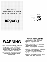
2. Bring incoming electrical service through the romex connector
and the fan knockout. Be sure to place the connector nut over the
wiring coming into the terminal box. There are three open ports
on the terminal strip. Using a small regular screwdriver, tighten
the Neutral (white) wire of the incoming supply under the open
terminal labeled "N". Tighten the Line (black) wire of the incoming
supply under the open terminal labeled "L". Tighten the Ground
(green) wire of the incoming supply under the open terminal labeled
" " (Figure 6). For reference, a wiring diagram is included on the
inside of the terminal box lid.
3. Secure the incoming supply with the romex connector and replace
the fan terminal box cover.
4. Restore power to the unit and test the installation.
SECTION 5
Finishing the Installation
1. Included with the unit is an identifying label that must be placed
above the dryer. This label serves as a reminder that there is a
booster fan installed and that periodic cleaning must take place.
SECTION 6
Use and Care
CAUTION: MAKE SURE POWER IS SWITCHED OFF AT SERVICE
PANEL BEFORE SERVICING THE UNIT.
1. Fan impeller may accumulate lint. Periodic inspection, based upon
dryer usage, should be performed to ensure that the fan impeller
is not obstructed or loaded with lint. Under normal conditions, fan
should be inspected a minimum of every Six (6) Months.To inspect
and clean the impeller:
a. Disconnect the incoming power supply at the source.
b. Remove the duct from the fan inlet and remove any lint buildup
on the impeller.
c. Reconnect the duct to the fan. Turn power supply on.
NOTE: Excessive booster fan noise or vibration may be an indication
of lint buildup on the impeller.
2. The fan’s bearings are sealed and provided with an internal
lubricating material, no additional lubrication is necessary.
NOTE: Steps 2 and 3 may be reversed.
SECTION 4
Electrical Connections
CAUTION: MAKE SURE POWER IS SWITCHED OFF AT SERVICE
PANEL BEFORE STARTING INSTALLATION.
CAUTION: ALL ELECTRICAL CONNECTIONS MUST BE MADE
IN ACCORDANCE WITH LOCAL CODES, ORDINANCES, OR NATIONAL
ELECTRICAL CODE. IF YOU ARE UNFAMILIAR WITH METHODS OF
INSTALLING ELECTRICAL WIRING, SECURE THE SERVICES OF A
QUALIFIED ELECTRICIAN.
NOTE: The fan motor, capacitor and pressure switch connections are
pre-wired from the factory.
1. Remove the screws securing the terminal box cover plate located
on the side of the fan. All fan motor connections are prewired to
an electrical terminal strip. A 3|8" romex type cable restraint
connector will be needed to secure the wiring through the knockout
provided on the side of the terminal box (Figure 5).
Bracket
Stud
Figure 4
Fan
Screws
Figure 3
Correct Positions
Incorrect Positions
Figure 5
Screws
Terminal Box
Supply from house
Green
Black
Ground
White
N
L
Figure 6
Black
White
Red
Brown
Blue
Black
Capacitor
kitchen::
accessories
Call 1-800-667-8721 anywhere in the US and Canada
Air King Dryer Booster Fans at
kitchen::
accessories
U N L I M I T E D

Troubleshooting Guide
Trouble Probable Cause Suggested Remedy
1. Fan does not operate when dryer begins cycle. 1a. A fuse may be blown or a circuit tripped. 1a. Replace fuse or reset circuit breaker.
1b. Wiring is not connected properly. 1b. Turn off power to unit. Check that all wires are connected.
1c. Pressure switch mounted incorrectly 1c. Turn off power to unit. Reposition switch in correct position.
1c. Motor has stopped operating. 1c. Replace motor.
2. Fan is operating, but air moves slower than normal. 2a. Obstruction in the exhaust ducting. 2a. Check for any obstructions in the ducting. The most common are bird nests
in the roof cap or wall cap where the fan exhausts to the outside.
3. Fan is operating louder than normal. 3a. Lint buildup in motor. 3a. Follow instructions in USE and CARE section of these instructions.
3b. Motor is loose. 3b. Turn off power to unit. Confirm unit is mounted securely to bracket.
Restore power to unit.
3c. Fan mounting screws too tight. 3c. Turn off power to the unit. Loosen screws going through rubber grommets
3d. Fan damaged in shipping. 3d. Contact seller for replacement.
LIMITED WARRANTY
All products manufactured by Air King Limited are warranted for one year from the date of purchase against defects in workmanship and/or
material. In addition, all ventilating/exhaust fans, heaters, combination fan lights and/or heaters, and range hoods are guaranteed for five years
from the date of purchase against defects in workmanship and/or material.
This warranty does not cover any labor or shipping costs or the cost of replacement components as part of routine maintenance such as: range
hood grease filters, charcoal filters or combination charcoal/grease filters; replacement light bulbs in range hoods or bathroom fan/light/bulb
heater combinations. As well, any damage or failure caused by abuse, misuse, abnormal usage, faulty installation, or improper maintenance
will not be covered by this warranty.
In order to make a claim on this warranty, you must be the original consumer of the product. You will be required to present to Air King the original
bill of sale showing: date of purchase, place of purchase and model purchased. Failure to meet these requirements will void your warranty.
Air King will not be held responsible for any bodily injury or damages to personal property or real estate whether caused directly or indirectly
by the product. Some states and provinces do not allow the exclusion or limitation of incidental or consequential damages and some states do
not allow limitations on how long an implied warranty lasts, so these exclusions or limitations may not apply to you. This warranty gives you
specific legal rights and you may have other rights which vary from state to state and province to province.
FOR PARTS OR TECHNICAL ASSISTANCE
Please call: 1-800-465-7300, MONDAY THROUGH FRIDAY, BETWEEN THE HOURS OF 8 AM AND 4:00 PM EST.
PLEASE DO NOT RETURN PRODUCT TO PLACE OF PURCHASE.
Reference the type and style of product (located on label inside of the product) when you call.
For more information please visit our website: wwwairkinglimited.com
AIDB4YEF New 3-07 4 of 8
Call 1-800-667-8721 anywhere in the US and Canada
1
2
3
4
5
6
8
# Qty. Description Replacement Part #
1 1 Motor 5S7635000
2 1 Cover Plate 5S7635029
3 2 Screw 5S7699021
4 1 Mounting Bracket 5S7635035
5 3 Grommet 5S7699020
6 3 Screw 5S7699024
7 1 Pressure Sensor Switch 5S7635046
8 8 Screw 5S7699022
9 1 Identifying Label 5S7635047
7
9
This dryer exhaust is equipped with an
Air King automatic dryer booster fan.
Verify proper operation each month:
Turn the dryer on for one minute than turn it
off. Verify that air keeps flowing through the
dryer filter opening after the dryer is off.
Air King
website: www.airkinglimited.com • phone 877-304-3785
Install on wall by dryer - DO NOT REMOVE
kitchen::
accessories
Air King Dryer Booster Fans at
kitchen::
accessories
U N L I M I T E D
/